EP0066921A2 - Filterelement - Google Patents
Filterelement Download PDFInfo
- Publication number
- EP0066921A2 EP0066921A2 EP82200624A EP82200624A EP0066921A2 EP 0066921 A2 EP0066921 A2 EP 0066921A2 EP 82200624 A EP82200624 A EP 82200624A EP 82200624 A EP82200624 A EP 82200624A EP 0066921 A2 EP0066921 A2 EP 0066921A2
- Authority
- EP
- European Patent Office
- Prior art keywords
- filter element
- tubes
- element according
- filter
- support
- Prior art date
- Legal status (The legal status is an assumption and is not a legal conclusion. Google has not performed a legal analysis and makes no representation as to the accuracy of the status listed.)
- Granted
Links
Images
Classifications
-
- B—PERFORMING OPERATIONS; TRANSPORTING
- B01—PHYSICAL OR CHEMICAL PROCESSES OR APPARATUS IN GENERAL
- B01D—SEPARATION
- B01D29/00—Filters with filtering elements stationary during filtration, e.g. pressure or suction filters, not covered by groups B01D24/00 - B01D27/00; Filtering elements therefor
- B01D29/11—Filters with filtering elements stationary during filtration, e.g. pressure or suction filters, not covered by groups B01D24/00 - B01D27/00; Filtering elements therefor with bag, cage, hose, tube, sleeve or like filtering elements
- B01D29/13—Supported filter elements
- B01D29/15—Supported filter elements arranged for inward flow filtration
-
- B—PERFORMING OPERATIONS; TRANSPORTING
- B01—PHYSICAL OR CHEMICAL PROCESSES OR APPARATUS IN GENERAL
- B01D—SEPARATION
- B01D29/00—Filters with filtering elements stationary during filtration, e.g. pressure or suction filters, not covered by groups B01D24/00 - B01D27/00; Filtering elements therefor
- B01D29/62—Regenerating the filter material in the filter
- B01D29/66—Regenerating the filter material in the filter by flushing, e.g. counter-current air-bumps
-
- B—PERFORMING OPERATIONS; TRANSPORTING
- B01—PHYSICAL OR CHEMICAL PROCESSES OR APPARATUS IN GENERAL
- B01D—SEPARATION
- B01D29/00—Filters with filtering elements stationary during filtration, e.g. pressure or suction filters, not covered by groups B01D24/00 - B01D27/00; Filtering elements therefor
- B01D29/62—Regenerating the filter material in the filter
- B01D29/70—Regenerating the filter material in the filter by forces created by movement of the filter element
-
- B—PERFORMING OPERATIONS; TRANSPORTING
- B01—PHYSICAL OR CHEMICAL PROCESSES OR APPARATUS IN GENERAL
- B01D—SEPARATION
- B01D29/00—Filters with filtering elements stationary during filtration, e.g. pressure or suction filters, not covered by groups B01D24/00 - B01D27/00; Filtering elements therefor
- B01D29/88—Filters with filtering elements stationary during filtration, e.g. pressure or suction filters, not covered by groups B01D24/00 - B01D27/00; Filtering elements therefor having feed or discharge devices
- B01D29/92—Filters with filtering elements stationary during filtration, e.g. pressure or suction filters, not covered by groups B01D24/00 - B01D27/00; Filtering elements therefor having feed or discharge devices for discharging filtrate
Definitions
- the invention relates to a filter element which is inserted into the housing of a pressure filter.
- a filter element of this type is known from DE-AS 2 114 226.
- the filter bags used in it are provided with various support bodies on the inside.
- the known filter elements with support bodies have brought about an improvement in the filtration properties. Due to the installation of support bodies of complicated geometry, difficulties arise during cleaning when backwashing the filter elements. The design of the inserts and the filter elements has also become more complex and has made the entire filter more expensive.
- the object of the invention is to provide a filter element which is simple, stable and easy to clean in its construction.
- the filter element characterized in claim 1, the support body of which consists of a bundle of tubes which is arranged around a central tube.
- the densest packing results in cross-section by arranging 6 tubes around the central tube.
- different diameters of the central tube and support tubes can also be used.
- the closed surface of the central tube is the preferred embodiment.
- the support tubes surrounding the central tube have openings on the long sides as particularly advantageous.
- the openings can be round or square, square, rectangular or polygonal.
- tubes with a closed surface can also surround the central tube.
- Plastic pipes have proven to be a particularly suitable material. The selection largely depends on the chemical properties of the suspension to be filtered. Metal pipes are also suitable, but plastic pipes are preferable for economic reasons.
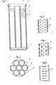
- the filter element consists of a base 1 and a cover 2.
- Support tubes 4 are arranged in the densest packing around a central tube 3.
- the central tube 3 has a closed tube surface.
- the support tubes 4 can partially consist of perforated tubes.
- About the A filter fabric 5 is stretched so that it forms a corrugated surface during the filtration from the outside inward and has a round cross section in the state of backwashing.
- the filter element can be fastened with a closure 6 in the support plate (not shown) of a filter kettle.
- the upper opening of the tubes 4 can be closed by the cover 2 or have an intermediate space between the cover and the upper edge.
- a particularly advantageous embodiment of the pipe openings are horizontal slots which can be produced in a simple manner by clamping the filter element on a lathe. This creates even, horizontal openings, the distance and diameter of which can be adjusted as required. Slots with an angle of 120 ° to the axis have proven to be particularly suitable.
- tubes as support elements for a filter fabric
- the use of tubes as support elements for a filter fabric has the advantage that the fabric can be supported in a simple manner and the filtrate can run off in the interspaces. It enters the lower part of the central pipe and leaves the pipe through its upper opening into the filtrate chamber of the filter kettle.
- the filtrate drain is significantly improved by perforating the support pipes.
Landscapes
- Chemical & Material Sciences (AREA)
- Chemical Kinetics & Catalysis (AREA)
- Filtering Materials (AREA)
- Filtration Of Liquid (AREA)
- External Artificial Organs (AREA)
- Piezo-Electric Or Mechanical Vibrators, Or Delay Or Filter Circuits (AREA)
- Networks Using Active Elements (AREA)
- Centrifugal Separators (AREA)
Abstract
Description
- Die Erfindung betrifft ein Filterelement, das in das Gehäuse eines Druckfilters eingesetzt wird.
- Ein Filterelement dieser Art ist aus der DE-AS 2 114 226 bekannt. Die darin verwendeten Filterschläuche sind mit verschiedenen Stützkörpern im Innern versehen. Die bekannten Filterelemente mit Stützkörpern haben eine Verbesserung der Filtrationseigenschaften gebracht. Durch den Einbau von Stützkörpern komplizierter Geometrie treten jedoch Schwierigkeiten während der Reinigung beim Rückspülen der Filterelemente auf. Die Konstruktion der Einsätze und der Filterelemente ist auch aufwendiger geworden und führte zu einer Verteuerung des gesamten Filters.
- Aufgabe der Erfindung ist es, ein Filterelement zu schaffen, das in seiner Konstruktion einfach, stabil und leicht zu reinigen ist.
- Diese Aufgabe wird erfindungsgemäss durch das in Anspruch 1 gekennzeichnete Filterelement gelöst, dessen Stützkörper aus einem Bündel von Rohren besteht, welches um ein Zentralrohr angeordnet ist.
- Bei gleichem Durchmesser aller Rohre ergibt sich im Querschnitt die dichteste Packung durch Anordnung von 6 Rohren um das Zentralrohr herum. Es können aber auch unterschiedliche Durchmesser von Zentralrohr und Stützrohren zur Anwendung kommen. In der Regel ist die geschlossene Oberfläche des Zentralrohres die vorgezogene Ausführungsform. Die das Zentralrohr umgebenden Stützrohre weisen Oeffnungen an den Längsseiten als besonders vorteilhaft auf. Dabei können die Oeffnungen rund oder eckig, quadratisch, rechteckig oder mehreckig ausgebildet sein. Es können aber auch Rohre mit einer geschlossenen Oeberfläche das Zentralrohr umgeben. Als besonders geeignetes Material haben sich Rohre aus Kunststoff erwiesen. Die Auswahl richtet sich weitgehend nach den chemischen Eigenschaften der Suspension, die filtriert werden soll. Auch Metallrohre sind geeignet, aus wirtschaftlichen Gründen jedoch sind Kunststoffrohre vorzuziehen.
- Die Erfindung soll anhand einer Zeichnung näher beschrieben werden. Es zeigen schematisch
- Figur leinen Längsschnitt durch das Filterelement,
- Figur 2 einen Querschnitt durch das Filterelement,
- Figuren 3, 4 und 5 verschiedene Rohrbohrungen.
- Das Filterelement besteht aus einem Boden 1 und einem Deckel 2. Um ein Zentralrohr 3 sind Stützrohre 4 in dichtester Packung angeordnet. Das Zentralrohr 3 weist eine geschlossene Rohrfläche auf. Die Stützrohre 4 können teilweise aus perforierten Rohren bestehen. Ueber das Rohrbündel ist ein Filtergewebe 5 derart gespannt, dass dieses während der Filtration von aussen nach innen eine wellenförmige Oberfläche bildet und im Zustand der Rückspülung einen runden Querschnitt aufweist. Das Filterelement kann mit einem Verschluss 6 in der nicht gezeigten Tragplatte eines Filterkessels befestigt werden. Die obere Oeffnung der Rohre 4 kann durch den Deckel 2 verschlossen oder einen Zwischenraum zwischen Deckel und oberen Rand aufweisen.
- Eine besonders vorteilhafte Ausgestaltung der Rohröffnungen sind waagerechte Schli.tze, die auf einfache Weise durch Einspannen des Filterelementes auf einer Drehbank hergestellt werden können. Dabei entstehen gleichmässige waagerechte Oeffnungen, deren Abstand und Druchmesser nach Wunsch eingestellt werden können. Schlitze mit einem Winkel von 1200 zur Achse haben sich dabei als besonders geeignet erwiesen.
- Die Verwendung von Rohren als Stützelemente für ein Filtergewebe hat den Vorteil, dass auf einfache Weise das Gewebe abgestützt und das Filtrat in den Zwischenräumen ablaufen kann. Es tritt in den unteren Teil des Zentralrohres ein und verlässt das Rohr durch seine obere Oeffnung in den Filtratraum des Filterkessels. Der Filtratablauf wird durch Perforierung der Stützrohre wesentlich verbessert.
Claims (11)
Priority Applications (1)
| Application Number | Priority Date | Filing Date | Title |
|---|---|---|---|
| AT82200624T ATE14990T1 (de) | 1981-06-01 | 1982-05-24 | Filterelement. |
Applications Claiming Priority (4)
| Application Number | Priority Date | Filing Date | Title |
|---|---|---|---|
| CH3548/81A CH655859A5 (en) | 1981-06-01 | 1981-06-01 | Filter element |
| CH3548/81 | 1981-06-01 | ||
| CH7045/81 | 1981-11-04 | ||
| CH704581 | 1981-11-04 |
Publications (3)
| Publication Number | Publication Date |
|---|---|
| EP0066921A2 true EP0066921A2 (de) | 1982-12-15 |
| EP0066921A3 EP0066921A3 (en) | 1983-05-18 |
| EP0066921B1 EP0066921B1 (de) | 1985-08-21 |
Family
ID=25693289
Family Applications (1)
| Application Number | Title | Priority Date | Filing Date |
|---|---|---|---|
| EP82200624A Expired EP0066921B1 (de) | 1981-06-01 | 1982-05-24 | Filterelement |
Country Status (10)
| Country | Link |
|---|---|
| US (1) | US4473472A (de) |
| EP (1) | EP0066921B1 (de) |
| AU (1) | AU549532B2 (de) |
| CA (1) | CA1189801A (de) |
| DE (1) | DE3265595D1 (de) |
| ES (1) | ES273596Y (de) |
| FI (1) | FI70523C (de) |
| IN (1) | IN157999B (de) |
| NO (1) | NO153677C (de) |
| YU (1) | YU42462B (de) |
Cited By (9)
| Publication number | Priority date | Publication date | Assignee | Title |
|---|---|---|---|---|
| DE3819137A1 (de) * | 1988-06-04 | 1989-12-07 | Krupp Koppers Gmbh | Filterelement |
| EP0491111A1 (de) * | 1990-12-17 | 1992-06-24 | Kamyr, Inc. | Atmosphärischer Diffusor mit Gegenstromreinigung der Unterfiltern |
| US5183536A (en) * | 1990-12-17 | 1993-02-02 | Kamyr, Inc. | Atmospheric diffuser improved lower screens backflushing |
| WO1993005860A1 (de) * | 1991-09-13 | 1993-04-01 | Drm, Dr. Müller Ag | Rückspülbares filterelement |
| US5525221A (en) * | 1993-04-19 | 1996-06-11 | Dr.M, Dr,Muller AG. | Sterile filtration candle filter for suspensions |
| WO1997004850A1 (de) * | 1995-08-02 | 1997-02-13 | Mavag Verfahrenstechnik Ag | Rohr-spiralkerze |
| WO2000016875A3 (de) * | 1998-09-21 | 2001-10-11 | Mueller Drm Ag | Kerzenfilterelement |
| WO2017024417A1 (de) | 2015-08-07 | 2017-02-16 | Drm, Dr. Müller Ag | Vorrichtung zum befestigen und abdichten von filtergeweben und membranschläuchen auf filterkerzen |
| DE102021105252A1 (de) | 2021-03-04 | 2022-09-08 | Bhs-Sonthofen Gmbh | Filterelement |
Families Citing this family (14)
| Publication number | Priority date | Publication date | Assignee | Title |
|---|---|---|---|---|
| US5639369A (en) * | 1995-07-14 | 1997-06-17 | W. L. Gore & Associates, Inc. | Filter element |
| US5711879A (en) * | 1996-03-04 | 1998-01-27 | American Metal Fibers | Radial-flow filter and method of manufacture |
| SE509834C2 (sv) * | 1996-09-09 | 1999-03-15 | Bandak As | Filterelement för tryckfilter |
| GB2415924B (en) * | 2004-07-06 | 2008-10-01 | Robert Irvine Anderson | Filter apparatus |
| CH703061A1 (de) * | 2010-04-19 | 2011-10-31 | Mueller Drm Ag | Filterelement aus Kunststoff. |
| US10058803B2 (en) | 2015-12-18 | 2018-08-28 | Synfuel Americas Corporation | Filter assembly and method of use |
| US11065566B2 (en) | 2018-03-23 | 2021-07-20 | Blue Skies Global LLC | Regenerative media filtration |
| US11167226B2 (en) | 2018-03-23 | 2021-11-09 | Blue Skies Global LLC | Regenerative media filtration |
| US10406458B1 (en) | 2018-03-23 | 2019-09-10 | Blue Skies Global LLC | Regenerative media filtration |
| US11679347B2 (en) | 2018-09-17 | 2023-06-20 | McFarlen Engineering Ltd. | Filter support element and method of using same |
| US12168190B2 (en) * | 2019-06-05 | 2024-12-17 | Ceco Environmental Ip Inc. | Self-cleaning filter |
| KR20240134966A (ko) | 2022-01-14 | 2024-09-10 | 렌징 악티엔게젤샤프트 | 캔들 필터 디바이스 |
| EP4463246A1 (de) | 2022-01-14 | 2024-11-20 | Lenzing Aktiengesellschaft | Kerzenfilterelement |
| US12215555B2 (en) * | 2023-03-21 | 2025-02-04 | Saudi Arabian Oil Company | Systems and methods for operating candle filters to recover glycols from drilling operations |
Family Cites Families (8)
| Publication number | Priority date | Publication date | Assignee | Title |
|---|---|---|---|---|
| CA727983A (en) * | 1966-02-15 | Muller Jacques | Filter element provided with one or more pre-filtering sheaths | |
| US3048275A (en) * | 1957-08-13 | 1962-08-07 | Bowser Inc | Filter-water separator |
| DE1141980B (de) * | 1958-10-09 | 1963-01-03 | Schwermaschb Iakarl Liebknecht | Rueckspuelbares Fluessigkeitsfilter |
| US3357564A (en) * | 1964-09-22 | 1967-12-12 | Halliburton Co | Filtering apparatus and method of making it |
| DE1611119A1 (de) * | 1967-11-08 | 1970-10-15 | Norddeutsche Seekabelwerke Ag | Filter aus Kunststoff |
| FR2031710A5 (de) * | 1969-02-04 | 1970-11-20 | Comptoir Filtration Cofi | |
| DE2625416C2 (de) * | 1976-06-05 | 1981-10-29 | Adolf Dipl.-Ing. 3060 Stadthagen Margraf | Staubgasfilter |
| GB2010691B (en) * | 1977-12-22 | 1982-06-16 | Chemap Ag | Filter elements and filters including them |
-
1982
- 1982-04-28 NO NO821399A patent/NO153677C/no not_active IP Right Cessation
- 1982-05-03 FI FI821541A patent/FI70523C/fi not_active IP Right Cessation
- 1982-05-04 YU YU947/82A patent/YU42462B/xx unknown
- 1982-05-24 DE DE8282200624T patent/DE3265595D1/de not_active Expired
- 1982-05-24 EP EP82200624A patent/EP0066921B1/de not_active Expired
- 1982-05-27 IN IN400/DEL/82A patent/IN157999B/en unknown
- 1982-05-31 ES ES1982273596U patent/ES273596Y/es not_active Expired
- 1982-05-31 AU AU84332/82A patent/AU549532B2/en not_active Ceased
- 1982-05-31 CA CA000404136A patent/CA1189801A/en not_active Expired
-
1983
- 1983-12-22 US US06/564,764 patent/US4473472A/en not_active Expired - Lifetime
Cited By (12)
| Publication number | Priority date | Publication date | Assignee | Title |
|---|---|---|---|---|
| DE3819137A1 (de) * | 1988-06-04 | 1989-12-07 | Krupp Koppers Gmbh | Filterelement |
| EP0491111A1 (de) * | 1990-12-17 | 1992-06-24 | Kamyr, Inc. | Atmosphärischer Diffusor mit Gegenstromreinigung der Unterfiltern |
| US5183536A (en) * | 1990-12-17 | 1993-02-02 | Kamyr, Inc. | Atmospheric diffuser improved lower screens backflushing |
| WO1993005860A1 (de) * | 1991-09-13 | 1993-04-01 | Drm, Dr. Müller Ag | Rückspülbares filterelement |
| US5435911A (en) * | 1991-09-13 | 1995-07-25 | Drm Dr. Mueller Ag | Back-washable filter element comprised of perforated tubes |
| US5525221A (en) * | 1993-04-19 | 1996-06-11 | Dr.M, Dr,Muller AG. | Sterile filtration candle filter for suspensions |
| WO1997004850A1 (de) * | 1995-08-02 | 1997-02-13 | Mavag Verfahrenstechnik Ag | Rohr-spiralkerze |
| WO2000016875A3 (de) * | 1998-09-21 | 2001-10-11 | Mueller Drm Ag | Kerzenfilterelement |
| US6860394B1 (en) | 1998-09-21 | 2005-03-01 | Drm, Dr. Mueller Ag | Candle filter element |
| WO2017024417A1 (de) | 2015-08-07 | 2017-02-16 | Drm, Dr. Müller Ag | Vorrichtung zum befestigen und abdichten von filtergeweben und membranschläuchen auf filterkerzen |
| US10486090B2 (en) | 2015-08-07 | 2019-11-26 | Drm, Dr. Mueller Ag | Filter device comprising filter candle for fastening and sealing filter fabrics and membrane tubes on a filter candle |
| DE102021105252A1 (de) | 2021-03-04 | 2022-09-08 | Bhs-Sonthofen Gmbh | Filterelement |
Also Published As
| Publication number | Publication date |
|---|---|
| FI70523B (fi) | 1986-06-06 |
| CA1189801A (en) | 1985-07-02 |
| NO153677B (no) | 1986-01-27 |
| IN157999B (de) | 1986-08-16 |
| FI70523C (fi) | 1986-09-24 |
| YU42462B (en) | 1988-08-31 |
| AU8433282A (en) | 1982-12-09 |
| AU549532B2 (en) | 1986-01-30 |
| NO153677C (no) | 1986-05-07 |
| US4473472A (en) | 1984-09-25 |
| DE3265595D1 (en) | 1985-09-26 |
| NO821399L (no) | 1982-12-02 |
| YU94782A (en) | 1985-03-20 |
| EP0066921B1 (de) | 1985-08-21 |
| ES273596U (es) | 1984-02-01 |
| EP0066921A3 (en) | 1983-05-18 |
| FI821541A0 (fi) | 1982-05-03 |
| ES273596Y (es) | 1985-03-16 |
Similar Documents
| Publication | Publication Date | Title |
|---|---|---|
| EP0066921B1 (de) | Filterelement | |
| DE3850792T2 (de) | Verfahren und Vorrichtung zum Filtrieren. | |
| EP0695211B1 (de) | Filterelement mit streckmetallmantel | |
| DE3839966A1 (de) | Hohlfadenmodul | |
| EP0038042A2 (de) | Filtriereinrichtung | |
| DE2846582A1 (de) | Vorrichtung zur membranfiltration | |
| DE2512781C3 (de) | Filterkerze mit riickspülbare Filterapparate | |
| DE3043011A1 (de) | Vorrichtung zum extrahieren von fluessigkeit aus sich bewegenden suspensionen | |
| EP0098643A2 (de) | Vorrichtung zur Befestigung von Filterkerzen | |
| DE1005493B (de) | Fluessigkeitsfilter mit in einer Kammer angeordneten Filterkoerpern | |
| EP0810018B1 (de) | Rückspülbare Filteranordnung und Filterkerze | |
| DE8605227U1 (de) | Rückspülfilter | |
| DE2803680A1 (de) | Reaktor fuer die kontinuierliche biologische reinigung von abwasser | |
| DE3874237T2 (de) | Sack fuer scheibenfiltersektor. | |
| CH655859A5 (en) | Filter element | |
| AT390567B (de) | Patronenfilter sowie filtereinrichtung | |
| EP0789611B1 (de) | Kerzenfiltervorrichtung für die bierfiltration | |
| CH658405A5 (en) | Filter element | |
| DE2835913A1 (de) | Rohrfiltervorrichtung | |
| EP0071200B1 (de) | Filterbehälter, insbesondere für Schwimmbecken | |
| DE928404C (de) | Filtereinsatz | |
| DE2801479C3 (de) | Filter mit einem aus körnigem Material bestehenden Bett | |
| DE1018845B (de) | Feinfilter fuer fluessige Kohlenwasserstoffe u. dgl. | |
| CH408860A (de) | Filterpresse | |
| DE29908293U1 (de) | Flüssigkeitsfilter |
Legal Events
| Date | Code | Title | Description |
|---|---|---|---|
| PUAI | Public reference made under article 153(3) epc to a published international application that has entered the european phase |
Free format text: ORIGINAL CODE: 0009012 |
|
| AK | Designated contracting states |
Designated state(s): AT BE CH DE FR GB IT LI LU NL SE |
|
| RAP1 | Party data changed (applicant data changed or rights of an application transferred) |
Owner name: DRM, DR. MUELLER AG |
|
| PUAL | Search report despatched |
Free format text: ORIGINAL CODE: 0009013 |
|
| ITCL | It: translation for ep claims filed |
Representative=s name: STUDIO JAUMANN |
|
| AK | Designated contracting states |
Designated state(s): AT BE CH DE FR GB IT LI LU NL SE |
|
| EL | Fr: translation of claims filed | ||
| TCNL | Nl: translation of patent claims filed | ||
| 17P | Request for examination filed |
Effective date: 19830526 |
|
| ITF | It: translation for a ep patent filed | ||
| GRAA | (expected) grant |
Free format text: ORIGINAL CODE: 0009210 |
|
| AK | Designated contracting states |
Designated state(s): AT BE CH DE FR GB IT LI LU NL SE |
|
| REF | Corresponds to: |
Ref document number: 14990 Country of ref document: AT Date of ref document: 19850915 Kind code of ref document: T |
|
| REF | Corresponds to: |
Ref document number: 3265595 Country of ref document: DE Date of ref document: 19850926 |
|
| ET | Fr: translation filed | ||
| PLBE | No opposition filed within time limit |
Free format text: ORIGINAL CODE: 0009261 |
|
| STAA | Information on the status of an ep patent application or granted ep patent |
Free format text: STATUS: NO OPPOSITION FILED WITHIN TIME LIMIT |
|
| 26N | No opposition filed | ||
| ITTA | It: last paid annual fee | ||
| EPTA | Lu: last paid annual fee | ||
| EAL | Se: european patent in force in sweden |
Ref document number: 82200624.3 |
|
| PGFP | Annual fee paid to national office [announced via postgrant information from national office to epo] |
Ref country code: AT Payment date: 20000407 Year of fee payment: 19 |
|
| PGFP | Annual fee paid to national office [announced via postgrant information from national office to epo] |
Ref country code: FR Payment date: 20000411 Year of fee payment: 19 |
|
| PGFP | Annual fee paid to national office [announced via postgrant information from national office to epo] |
Ref country code: SE Payment date: 20000417 Year of fee payment: 19 |
|
| PGFP | Annual fee paid to national office [announced via postgrant information from national office to epo] |
Ref country code: GB Payment date: 20000419 Year of fee payment: 19 |
|
| PGFP | Annual fee paid to national office [announced via postgrant information from national office to epo] |
Ref country code: NL Payment date: 20000425 Year of fee payment: 19 Ref country code: DE Payment date: 20000425 Year of fee payment: 19 |
|
| PGFP | Annual fee paid to national office [announced via postgrant information from national office to epo] |
Ref country code: LU Payment date: 20000515 Year of fee payment: 19 Ref country code: BE Payment date: 20000515 Year of fee payment: 19 |
|
| PGFP | Annual fee paid to national office [announced via postgrant information from national office to epo] |
Ref country code: CH Payment date: 20000824 Year of fee payment: 19 |
|
| PG25 | Lapsed in a contracting state [announced via postgrant information from national office to epo] |
Ref country code: LU Free format text: LAPSE BECAUSE OF NON-PAYMENT OF DUE FEES Effective date: 20010524 Ref country code: GB Free format text: LAPSE BECAUSE OF NON-PAYMENT OF DUE FEES Effective date: 20010524 Ref country code: AT Free format text: LAPSE BECAUSE OF NON-PAYMENT OF DUE FEES Effective date: 20010524 |
|
| PG25 | Lapsed in a contracting state [announced via postgrant information from national office to epo] |
Ref country code: SE Free format text: LAPSE BECAUSE OF NON-PAYMENT OF DUE FEES Effective date: 20010525 |
|
| PG25 | Lapsed in a contracting state [announced via postgrant information from national office to epo] |
Ref country code: BE Free format text: LAPSE BECAUSE OF NON-PAYMENT OF DUE FEES Effective date: 20010531 |
|
| PG25 | Lapsed in a contracting state [announced via postgrant information from national office to epo] |
Ref country code: LI Free format text: LAPSE BECAUSE OF NON-PAYMENT OF DUE FEES Effective date: 20010623 Ref country code: CH Free format text: LAPSE BECAUSE OF NON-PAYMENT OF DUE FEES Effective date: 20010623 |
|
| BERE | Be: lapsed |
Owner name: MULLER A.G. Effective date: 20010531 |
|
| PG25 | Lapsed in a contracting state [announced via postgrant information from national office to epo] |
Ref country code: NL Free format text: LAPSE BECAUSE OF NON-PAYMENT OF DUE FEES Effective date: 20011201 |
|
| REG | Reference to a national code |
Ref country code: CH Ref legal event code: PL |
|
| GBPC | Gb: european patent ceased through non-payment of renewal fee |
Effective date: 20010524 |
|
| PG25 | Lapsed in a contracting state [announced via postgrant information from national office to epo] |
Ref country code: FR Free format text: LAPSE BECAUSE OF NON-PAYMENT OF DUE FEES Effective date: 20020131 |
|
| NLV4 | Nl: lapsed or anulled due to non-payment of the annual fee |
Effective date: 20011201 |
|
| PG25 | Lapsed in a contracting state [announced via postgrant information from national office to epo] |
Ref country code: DE Free format text: LAPSE BECAUSE OF NON-PAYMENT OF DUE FEES Effective date: 20020301 |