EP0066433A1 - Drive system and method for moving a vehicle along a rail track - Google Patents
Drive system and method for moving a vehicle along a rail track Download PDFInfo
- Publication number
- EP0066433A1 EP0066433A1 EP82302623A EP82302623A EP0066433A1 EP 0066433 A1 EP0066433 A1 EP 0066433A1 EP 82302623 A EP82302623 A EP 82302623A EP 82302623 A EP82302623 A EP 82302623A EP 0066433 A1 EP0066433 A1 EP 0066433A1
- Authority
- EP
- European Patent Office
- Prior art keywords
- drive
- rail
- vehicle
- drive assembly
- clamp
- Prior art date
- Legal status (The legal status is an assumption and is not a legal conclusion. Google has not performed a legal analysis and makes no representation as to the accuracy of the status listed.)
- Withdrawn
Links
Images
Classifications
-
- B—PERFORMING OPERATIONS; TRANSPORTING
- B61—RAILWAYS
- B61J—SHIFTING OR SHUNTING OF RAIL VEHICLES
- B61J3/00—Shunting or short-distance haulage devices; Similar devices for hauling trains on steep gradients or as starting aids; Car propelling devices therefor
- B61J3/12—Self-propelled tractors or pushing vehicles, e.g. mules
-
- B—PERFORMING OPERATIONS; TRANSPORTING
- B61—RAILWAYS
- B61K—AUXILIARY EQUIPMENT SPECIALLY ADAPTED FOR RAILWAYS, NOT OTHERWISE PROVIDED FOR
- B61K7/00—Railway stops fixed to permanent way; Track brakes or retarding apparatus fixed to permanent way; Sand tracks or the like
-
- B—PERFORMING OPERATIONS; TRANSPORTING
- B61—RAILWAYS
- B61J—SHIFTING OR SHUNTING OF RAIL VEHICLES
- B61J3/00—Shunting or short-distance haulage devices; Similar devices for hauling trains on steep gradients or as starting aids; Car propelling devices therefor
Definitions
- This invention relates to a drive system for a rail mounted vehicle, and to a method of moving such a vehicle along a rail track.
- Pusher devices for moving railway vehicles through loading and unloading stations are known, and are also in fairly common usage in railway yards to reduce shunting activities. It is, for example, known to provide means for moving a railway vehicle through a loading or unloading station which includes at least one actuator adapted to be mounted on the railway vehicle and to be operated cyclically with successive extension and retraction strokes.
- the or each actuator is provided with means adapted to engage and release anchor means located along the track of the vehicle; the arrangement being such that, through engagement with the anchor means, the actuator pulls or pushes the vehicle on which it is mounted through a predetermined distance during each extension and retraction cycle.
- a disadvantage of the above system is that the provision of the anchor means along the track can be relatively costly, and it is accordingly an object of the present invention tu provide a novel drive system which it is believed will minimise this disadvantage.
- a drive system for a rail mounted vehicle comprises a drive assembly adapted to be mounted on the vehicle and to be operated cyclically having a drive cycle and a non-drive cycle; the drive assembly including engagement means adapted to engage and release the track on which the vehicle is mounted synchronously with the cyclic operation of the assembly; the arrangement being such that,during the drive cycle of the drive assembly, the engagement means engages the track so that the drive assembly pushes or pulls the vehicle along the track; and, during the non-drive cycle of the drive assembly, the engagement means releases the track and is advanced therealong.
- the engagement means will be clamping means adapted to clamp onto the rail, although it is also intended to include within the scope of the invention an arrangement wherein the engagement means abuts formations on the rail.
- the operating assembly will be in the nature of a reciprocable, fluid operable ram, adapted to have one end thereof secured to the vehicle, while the other end terminates in the engagement means.
- the drive assembly could be adapted to perform rotary or reciprocating arcuate movement, but such an arrangement is not preferred.
- a pair of drive assemblies is provided and adapted to operate sequentially so as to move the train along the rail in a substantially uninterrupted manner.
- the drive assemblies may be mounted one behind the other, and with a double rail the drive assemblies could be thus mounted or be mounted adjacent one another. It will be appreciated that various possibilities will present themselves with regard to the disposition of the drive assemblies.
- the engagement means is in the nature of a clamp
- the latter includes a clamping jaw and a lever system adapted to operate the jaw.
- the lever system may in turn be operated by an electrical actuator, fluid actuator, or the like.
- the clamp could comprise a pair of opposed first degree levers which define the clamping jaw towards their one pair of ends, and with actuating means being provided at the other pair of ends to move these towards or away from one another to effect the release or clamping of the jaw formations.
- the cross-sectional width of the clamping jaws do not exceed the width of a conventional wheel flange so that the clamping jaw will be afforded the same passage as the wheel flange on a rail.
- a method of moving a rail mounted vehicle along a rail comprising the steps of providing a drive assembly on the vehicle, causing the drive assembly to operate cyclically through a drive cycle and a non-drive cycle; causing the drive assembly to engage the rail on which the vehcile is mounted during its drive cycle so that the vehicle is pushed or pulled along the rail; and causing the drive assembly to release the rail during its non-drive cycle to advance the drive assembly relative to the rail.
- the drive assembly will engage the rail by means of a clamping operation.
- a pair of drive assemblies is provided and adapted to operate sequentrally so that the vehicle is moved along the rail in a substantially uninterrupted manner.
- the drive assembly is reciprocated to perform it cyclical operations.
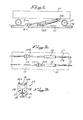
- the rams 12 will reciprocate sequentially and the clamps 13 will clamp onto the rails 11 during the power stroke of the rams 12 and release the rails 11 during the return stroke, and in such manner move the vehicle 10 along the rails 11 in a substantially uninterrupted manner. It will be appreciated that a single ram 12 and clamp 13 could also move the vehicle 10 along the rails 11 but in such a case movement will be periodic.
- the clamp 13 comprises a pair of opposed first degree levers 14 which are pivotally mounted, at 15, with the one free end of each lever 14 providing a clamping tooth 18, while the other end is pivotally secured, at 16a, to an interlinking ram 16.
- extension of ram 16 will move the clamping teeth 18 towards one another to perform a clamping operation, while retraction of the ram 16 will have the reverse effect to move the clamping teeth 18 away from one another in the nature of a releasing action.
- operation of the levers 14 could be by means of an electrical solenoid, eccentric clamps etc.
- the. clamps 13 will clamp onto the head of a rail 11 as shown in Figure 3, and in this way the force applied to the rail 11 during operation of the rams will be mainly longitudinal with no ill effect on the rail line. It is believed that, with the arrangement of the invention, the vertical component of force; generated by the rams 12 could be balanced with a relatively low ballast. It will be appreciated that, where traction is applied to wheels 17 of the vehicle 10, a ballast which is four times greater than the tractive force is required. Other advantages of the arrangement of the invention will be apparent to persons skilled in the art.
- the width of clamping teeth 18 will preferably be equal to, or less than, the width of the flange 17a of a conventional railroad wheel 17, so that the teeth 18 will be afforded the same passage on the railroad line as that of the flanges 17a.
- the expression "rail mounted vehicle” herein means a vehicle adapted to move along a guideway, and the term “rail” must be interpreted accordingly.
Landscapes
- Engineering & Computer Science (AREA)
- Mechanical Engineering (AREA)
- Automobile Manufacture Line, Endless Track Vehicle, Trailer (AREA)
- Vehicle Body Suspensions (AREA)
- Automatic Disk Changers (AREA)
- Seats For Vehicles (AREA)
- Machines For Laying And Maintaining Railways (AREA)
Applications Claiming Priority (2)
| Application Number | Priority Date | Filing Date | Title |
|---|---|---|---|
| ZA813450 | 1981-05-22 | ||
| ZA813450 | 1981-05-22 |
Publications (1)
| Publication Number | Publication Date |
|---|---|
| EP0066433A1 true EP0066433A1 (en) | 1982-12-08 |
Family
ID=25575425
Family Applications (1)
| Application Number | Title | Priority Date | Filing Date |
|---|---|---|---|
| EP82302623A Withdrawn EP0066433A1 (en) | 1981-05-22 | 1982-05-21 | Drive system and method for moving a vehicle along a rail track |
Country Status (14)
| Country | Link |
|---|---|
| EP (1) | EP0066433A1 (Direct) |
| JP (1) | JPS5820555A (Direct) |
| KR (1) | KR830009970A (Direct) |
| AR (1) | AR228656A1 (Direct) |
| AU (1) | AU8403982A (Direct) |
| BR (1) | BR8202963A (Direct) |
| ES (1) | ES8308777A1 (Direct) |
| FI (1) | FI821819A7 (Direct) |
| GR (1) | GR76797B (Direct) |
| IL (1) | IL65874A0 (Direct) |
| MA (1) | MA22570A1 (Direct) |
| PT (1) | PT74942B (Direct) |
| ZM (1) | ZM3682A1 (Direct) |
| ZW (1) | ZW10782A1 (Direct) |
Cited By (3)
| Publication number | Priority date | Publication date | Assignee | Title |
|---|---|---|---|---|
| WO1991009763A1 (fr) * | 1989-12-21 | 1991-07-11 | Track Holding S.A. | Dispositif de propulsion pour une rame pour le renouvellement de voies ferrees |
| US5261331A (en) * | 1989-12-21 | 1993-11-16 | Harsco Corporation | Propulsion device for a train intended for renewal of railway tracks utilizing rail grippers to supply propulsion thrust |
| CN102211589A (zh) * | 2011-03-28 | 2011-10-12 | 枣庄矿业(集团)有限责任公司蒋庄煤矿 | 变电列车液压拖移装置 |
Citations (4)
| Publication number | Priority date | Publication date | Assignee | Title |
|---|---|---|---|---|
| DE40751C (de) * | R. H. LA-PAGE in Bank Chambers, New - Oxford Street, Middlesex, England | Vorrichtung zum Bewegen von Fahrzeugen auf starken Steigungen | ||
| GB864073A (en) * | 1957-05-13 | 1961-03-29 | Selma Moenninghoff | A tub-pusher |
| DE1605362A1 (de) * | 1967-10-17 | 1971-01-07 | Pohlig Heckel Bleichert | Selbstfahrender Rangierwagen |
| GB1231780A (Direct) * | 1969-12-24 | 1971-05-12 |
-
1982
- 1982-05-20 ZW ZW107/82A patent/ZW10782A1/xx unknown
- 1982-05-21 AU AU84039/82A patent/AU8403982A/en not_active Abandoned
- 1982-05-21 MA MA19691A patent/MA22570A1/fr unknown
- 1982-05-21 BR BR8202963A patent/BR8202963A/pt unknown
- 1982-05-21 FI FI821819A patent/FI821819A7/fi not_active Application Discontinuation
- 1982-05-21 ES ES512450A patent/ES8308777A1/es not_active Expired
- 1982-05-21 EP EP82302623A patent/EP0066433A1/en not_active Withdrawn
- 1982-05-21 AR AR289489A patent/AR228656A1/es active
- 1982-05-21 GR GR68218A patent/GR76797B/el unknown
- 1982-05-21 ZM ZM36/82A patent/ZM3682A1/xx unknown
- 1982-05-21 PT PT74942A patent/PT74942B/pt unknown
- 1982-05-22 JP JP57085697A patent/JPS5820555A/ja active Pending
- 1982-05-22 KR KR1019820002257A patent/KR830009970A/ko not_active Withdrawn
- 1982-05-25 IL IL65874A patent/IL65874A0/xx unknown
Patent Citations (4)
| Publication number | Priority date | Publication date | Assignee | Title |
|---|---|---|---|---|
| DE40751C (de) * | R. H. LA-PAGE in Bank Chambers, New - Oxford Street, Middlesex, England | Vorrichtung zum Bewegen von Fahrzeugen auf starken Steigungen | ||
| GB864073A (en) * | 1957-05-13 | 1961-03-29 | Selma Moenninghoff | A tub-pusher |
| DE1605362A1 (de) * | 1967-10-17 | 1971-01-07 | Pohlig Heckel Bleichert | Selbstfahrender Rangierwagen |
| GB1231780A (Direct) * | 1969-12-24 | 1971-05-12 |
Cited By (4)
| Publication number | Priority date | Publication date | Assignee | Title |
|---|---|---|---|---|
| WO1991009763A1 (fr) * | 1989-12-21 | 1991-07-11 | Track Holding S.A. | Dispositif de propulsion pour une rame pour le renouvellement de voies ferrees |
| AU641716B2 (en) * | 1989-12-21 | 1993-09-30 | Harsco Corporation | Propulsion device for a railway modernization flatcar |
| US5261331A (en) * | 1989-12-21 | 1993-11-16 | Harsco Corporation | Propulsion device for a train intended for renewal of railway tracks utilizing rail grippers to supply propulsion thrust |
| CN102211589A (zh) * | 2011-03-28 | 2011-10-12 | 枣庄矿业(集团)有限责任公司蒋庄煤矿 | 变电列车液压拖移装置 |
Also Published As
| Publication number | Publication date |
|---|---|
| FI821819A0 (fi) | 1982-05-21 |
| IL65874A0 (en) | 1982-08-31 |
| ZM3682A1 (en) | 1983-04-21 |
| PT74942B (en) | 1983-11-30 |
| AR228656A1 (es) | 1983-03-30 |
| ES512450A0 (es) | 1983-10-01 |
| GR76797B (Direct) | 1984-09-04 |
| ZW10782A1 (en) | 1982-07-14 |
| AU8403982A (en) | 1982-11-25 |
| MA22570A1 (fr) | 1993-04-01 |
| ES8308777A1 (es) | 1983-10-01 |
| KR830009970A (ko) | 1983-12-24 |
| FI821819A7 (fi) | 1982-11-23 |
| PT74942A (en) | 1982-06-01 |
| JPS5820555A (ja) | 1983-02-07 |
| BR8202963A (pt) | 1983-05-03 |
Similar Documents
| Publication | Publication Date | Title |
|---|---|---|
| CA3057794C (en) | Drone tamper | |
| CN208022283U (zh) | 一种医院物流轨道转换器 | |
| EP0066433A1 (en) | Drive system and method for moving a vehicle along a rail track | |
| CN214656047U (zh) | 应用换轨工程车 | |
| DE518799C (de) | Als selbstaendiges Fahrzeug ausgebildeter, auf Nebengleisen fahrbarer Wagenschlepper mit einschwenkbaren Mitnehmern | |
| CN214782947U (zh) | 一种平移式齿轨道岔 | |
| DE1190490B (de) | Verfahren und Vorrichtung zum Automatisieren des Ablaufvorganges in Rangierbahnhoefen | |
| GB1068754A (en) | Apparatus and method for shunting rolling stock | |
| CN103612925A (zh) | 一种磁动力翻车机卸车系统及其卸车方法 | |
| RU2213823C2 (ru) | Устройство для завинчивания и отвинчивания гаек промежуточного рельсового скрепления железнодорожного пути | |
| DE10143287B4 (de) | Verfahren und Anordnung zum Positionieren von Förderwagen | |
| CN114481725A (zh) | 轨道安装装置 | |
| US4574706A (en) | Conveyor system with alternative carrier propulsion | |
| CN218756813U (zh) | 一种轨道交通维修矫正器 | |
| DE1909203B2 (de) | Rangiervorrichtung für Eisenbahnwagen mit einem Hilfsgleis fur einen Schlepp- und Bremswagen | |
| SU765630A1 (ru) | Толкатель двустороннего действи | |
| DE102005026822B3 (de) | Verfahren und Vorrichtung zum Abbremsen eines Transportmittels | |
| DE102584C (Direct) | ||
| CN211075909U (zh) | 道岔用扳道器 | |
| DE202888C (Direct) | ||
| JPH0744191U (ja) | 単軌条運搬車装置 | |
| GB1369824A (en) | Tie indexing devices for railway track maintenance machines | |
| SU1449613A1 (ru) | Устройство дл передвижки шпал | |
| SU983161A1 (ru) | Устройство дл укладки звеньев рельсового пути | |
| DE2452254C3 (de) | Förderanlage für Eisenbahnwagen |
Legal Events
| Date | Code | Title | Description |
|---|---|---|---|
| PUAI | Public reference made under article 153(3) epc to a published international application that has entered the european phase |
Free format text: ORIGINAL CODE: 0009012 |
|
| 17P | Request for examination filed |
Effective date: 19820816 |
|
| AK | Designated contracting states |
Designated state(s): AT BE CH DE FR GB IT LU NL SE |
|
| STAA | Information on the status of an ep patent application or granted ep patent |
Free format text: STATUS: THE APPLICATION IS DEEMED TO BE WITHDRAWN |
|
| 18D | Application deemed to be withdrawn |
Effective date: 19841123 |
|
| RIN1 | Information on inventor provided before grant (corrected) |
Inventor name: RABINOVITCH, JOSEF KIVVOVICH |