EP0064686A1 - Système de transmission de messages - Google Patents
Système de transmission de messages Download PDFInfo
- Publication number
- EP0064686A1 EP0064686A1 EP82103692A EP82103692A EP0064686A1 EP 0064686 A1 EP0064686 A1 EP 0064686A1 EP 82103692 A EP82103692 A EP 82103692A EP 82103692 A EP82103692 A EP 82103692A EP 0064686 A1 EP0064686 A1 EP 0064686A1
- Authority
- EP
- European Patent Office
- Prior art keywords
- transmission system
- message transmission
- stations
- control center
- correlators
- Prior art date
- Legal status (The legal status is an assumption and is not a legal conclusion. Google has not performed a legal analysis and makes no representation as to the accuracy of the status listed.)
- Granted
Links
Images


Classifications
-
- H—ELECTRICITY
- H04—ELECTRIC COMMUNICATION TECHNIQUE
- H04W—WIRELESS COMMUNICATION NETWORKS
- H04W88/00—Devices specially adapted for wireless communication networks, e.g. terminals, base stations or access point devices
- H04W88/08—Access point devices
Definitions
- the invention relates to a message transmission system with fixed transceiver stations and with movable transceiver stations which can exchange messages by radio with the fixed stations, several fixed stations being controlled by a control center, several of which in turn are controlled by a gateway to a telephone switched network are connected.
- Adjacent channel interference is only possible due to the high frequency stability of the modules used and steep channel filters reduce, which requires a relatively high effort, as well as the avoidance of intermodulation products due to a non-linear amplitude characteristic in the receiving channel. In addition, there is the low interference immunity of the analog message transmission.
- the invention is based on the object of specifying a message transmission system of the type mentioned at the outset which permits (n) cost-effective production and operation, in particular of the mobile transmitting / receiving stations, and a flexible expansion to a very large number of subscribers, and thereby mutual interference and disruptions from avoids other radio services with a secure transmission and suppresses interference from multipath reception.
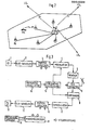
- the message transmission system shown in Fig. 1 is divided into three levels.
- the lowest level is the radio level, in which communication with the mobile transmitting / receiving stations is operated in a specific area with the aid of a fixed transmitting / receiving station.
- the moving stations are indicated by a thick dot and the stationary stations are indicated by a solid square.
- the approximate area of a fixed transmitting / receiving station is indicated by a dash-dotted line.
- control center In the cell level above it, several stationary transmitting / receiving stations are connected to a control center. Each control center supplies one cell.
- the control center organizes radio communication within its cell and forwards the calls to a gateway.
- the control centers are identified by a filled square in a square. The delimitation of the cells from each other is indicated by dashed lines.
- all control centers are connected to one another and a transfer device is assigned to several control centers.
- the gateway establishes the connection to the telephone switched network.
- the transfer device can be connected locally to a control center.
- the transfer devices are identified by a circle with dots and the demarcation between the areas of the transfer devices is indicated by a dashed line.
- the connections of the control centers with each other on the system level are used for data exchange between all control centers and thus the higher-level organization of the system, in particular for recording the location of the mobile stations and for transferring calls.
- the connections between the fixed transmitting / receiving stations and the control centers and between the control centers are made through a broadband transmission medium. It can carry a cable connection, an optical light w elle conductor connection or be realized by radio.
- FIG. 2 shows a control center with its cell.
- Six fixed transmitting / receiving stations FS are connected to the control center LS, one of which is at the location of the Control center can be set up.
- a movable transceiver station MS is shown, which is connected to the fixed station FS via the radio link, symbolized by a broken arrow.
- the connections between the fixed stations FS and the control center LS are constructed, for example, from optical fibers.
- the connection of the control center LS to the neighboring control centers LS x , LS y and LS is realized, for example, by radio relay links.
- the fixed transmitting / receiving stations are arranged from the viewpoint of sufficient coverage in the entire cell, and their number is selected accordingly.
- the radio transmission between the mobile and the stationary stations takes place in duplex traffic in the frequency range of, for example, 900 MHz in time division multiplex with multiple access.
- the control center uses organizational measures to ensure that no co-channel interference occurs.
- the fixed stations are able to communicate simultaneously on several channels in time-division multiplex, but they only act as relay stations of the control center during the conversation.
- the stationary stations determine the area of responsibility in which the moving stations are located. This information is evaluated in the control center.
- control center LS In addition to the processing of calls and data from all fixed stations FS, the control center LS ensures the decentralized organization of all processes within its cell. It decides on the allocation of channels, the change of the serving stationary station and, if necessary, arranges the transfer to the next cell. For this purpose, the control center has transmission facilities and a directions for data processing and storage for the subscriber numbers in the cell area, the assigned channels, the active and callable moving stations with their local position and associated stationary station.
- the radio transmission takes place in time division multiplex.
- messages are transmitted as a series of short pulses, and the temporal nesting of series of pulses results in the different time slots or channels.
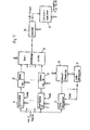
- 3 shows the block diagram of a movable transceiver station which works in time division multiplexing.
- An analog / digital converter (A / D) 2 which converts an analog signal into binary characters, is connected to a microphone 1.
- the binary characters arrive in a buffer memory 3, in which they are temporarily stored until they modulate the carrier oscillation in a subsequent modulator 4 in the assigned time slot in a compressed form.
- a transmitter 5 which works via a transmit / receive switch (S / E) 6 on an antenna 7, which radiates the correspondingly prepared carrier oscillation.
- the modulator 4 and a receiver 8 are connected to a frequency generator 15, which is controlled by a reference oscillator 16.
- the S / E switch 6 is followed by the receiver 8, which converts the received signals into an intermediate frequency.
- the signals are demodulated and buffered in a subsequent buffer memory 10. From this they are read out spread and converted back into an analog signal by a digital / analog converter (D / A) 11 and reproduced by a receiver or loudspeaker 12.
- D / A digital / analog converter
- the microprocessor 13 takes on organizational tasks such as synchronization on the time grid, setting of the time slots, sending of call, identification and acknowledgment signals and processing of the control commands coming from the stationary station. For this purpose, it is connected to the buffer memories 3 and 10 and the S / E switch 6 via control lines.
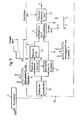
- the stationary station has an antenna 7, a receiver 8, a demodulator 9 in the receiving branch and a transmitter 5, a modulator 4 in the transmitting branch, and a reference oscillator 16 and a frequency generator 15.
- a microprocessor 13 which is connected to the corresponding modules by control lines.
- a multiplexer 17 is arranged in the transmission branch in front of the modulator 4, which combines the multiple messages buffered in N buffer memories 18 in the correct chronological order.
- N stands for the number of time slots or channels.
- the buffer memories 18 are connected to a device 19 for converting and forwarding the messages.
- a demultiplexer 20 is connected to the demodulator 9, which distributes the received time-nested messages back to N buffer memories 21.
- the buffer memories 21 are connected to the device 19.
- the type of implementation of the individual receive and transmit signals in the device 19 for transmission to the control and the control center depends on which medium is used. At any point in time, because of the multiple access selected in time division multiplexing, only one mobile transceiver station is connected to the fixed transceiver station. Mutual interference is therefore not possible.
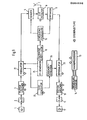
- a time frame with N 64 time slots is selected, which is repeated periodically at a rate of 30 per second.
- FIG. 5 shows such a time frame and a single time slot, which is also referred to as a channel.
- the time frame is 1/30 second long and contains 64 time slots, of which only the first three time slots, marked 1,2,3, and the last time slot, marked 64, are shown.
- Time slot number 2 is enlarged and shown with possible occupancy. It begins with a synchronization preamble, which enables the recipients to synchronize with the received message.
- a subsequent message preamble contains the data necessary for the organization, such as time slot and user number.
- the following part of the message contains approximately 2130 bits and represents the speech information of an interval of 1/30 second duration. It follows that the speech digitization takes place at 64 kbit / s.
- Each time slot ends with a protection time, which is used to take into account run times. With these values, a bit rate of approximately 5 Mbit / s and a required bandwidth of approximately 5 MHz, depending on the type of modulation used, are calculated. Two such frequency ranges are required for duplex operation.
- the control center takes the various organizational measures for the area of a cell. Communication at the radio level is handled by only one fixed station for each mobile station in order to avoid interference of the signals. The responsibility of a stationary station for a mobile station is determined via the amplitude or transit time of the signal of the mobile station. Decisions about a change, for example when moving a station, are made only by the control center.
- the transfer between stationary stations is triggered by control commands to the two stations concerned from the control center as soon as it recognizes the necessity as a result of the ongoing vehicle location determination. As a rule, it is not necessary to change the assigned channel.
- the control center in whose cell the conversation began is always connected to the public telephone network. Therefore, there are two tasks to be performed here when there is a call. First, the operating control center must be in Cooperation with the neighboring control center organize the handover to a stationary neighboring station, whereby a new channel may have to be assigned, and secondly, the "new" control center has to forward the call to the "old" control center so that it can continue from there got into the telephone network.
- the prerequisite for establishing the connection is the contact of the mobile station with a stationary station. This contact is always given when the device of the mobile station is switched on, even if no conversation is in progress, because the identifier is automatically sent on a special channel at certain time intervals (e.g. every 1 ... 2 min). This identifier is continuously recorded and evaluated.
- the control center maintains a list of all mobile stations within the cell that are ready to talk and informs the memory in the home cell about the current location of mobile stations outside the cell. After a cell change, the lists in the two control centers are corrected. The change is also reported to the home cell of the mobile station.
- an inquiry is first made to the control center in the home cell that can be recognized from the phone number. This has saved whether the called mobile station is ready to talk and if so, where it is located. The currently responsible control center is selected. She calls the mobile station on the special call channel and assigns it a conversation channel on which the call is then processed.
- Countermeasures that are frequently used are diversity processes, e.g. Multiple transmission and coding for error correction, the former requiring comparatively little effort, but generally also has little effectiveness.
- Encoding for error correction is in connection very effective with character reorganization with suitable design.
- the two methods mentioned have in common that they start after a decision - possibly incorrect - has been made about the characters received.
- the procedure described below, on the other hand, tries to suppress incorrect decisions from the outset.
- the starting point is the consideration that multipath signals do not lead to interference if they can be detected separately.
- the spectrum spreading methods offer favorable conditions for this. If signals with the bandwidth B are transmitted, their arrival times can be determined with an accuracy of order 1 / B. By spreading the bandwidth by a factor of n, the time interval for the discovery shrinks to an nth of the original value.
- the signals are spread in such a way that the digitized signals are multiplied by a code. If the clock frequency of the code corresponds to the width of the transmission band, the initially narrow-band signal is spread over the entire band in this way. On the receiving side, the received, spread signal is multiplied again with the same code after synchronization has taken place in a correlation process. As a result, the desired signal is generated in the original narrow message band, while unwanted signals remain broadband and are therefore not evaluated. Your interference depends on the cross correlation of the ver averted codes.
- FIG. 6a A digitized signal is shown in FIG. 6a and in FIG. 6 b shows a code consisting of the same repeating code words for spreading the signal.
- the spread signal is shown in FIG. 6c, from which it can be seen that with a binary zero in 6a the code in 6b is inverted and with a binary one it is not inverted.
- the signs of the direct signal are identified with 1, 2, 3, 4 and those of the detour signals with 'or ".
- the detected signals are recorded underneath. It can be clearly seen how signals that overlap in time are resolved due to the band spread 7, however, also shows that it is desirable to extend the decision period for each character to such an extent that as few detour signals as possible fall within the decision period of the following character.
- the characters 1 "and 2" interfere with the decision for characters 2 and 5, respectively 3.
- Two reception signals are available for the decision due to the multipath propagation, for example 1 and 1' Reduction of the probability of receiving signals that cannot be correctly evaluated due to fading.
- the decision period for each bit is 200 ns. This would detour signals with a path difference of more than 60 m to the direct signal in the Ent divorce period following characters.
- n bits are combined to form an n-bit group and replaced by an m-valued code character.
- the possible variants of the 4-bit group are partially shown for n equal to 4 in the left column and the code characters obtained by cyclical exchange are shown partially in the right column for m equal to 16.
- the time interval for the discovery is shortened by the same factor, so that signals with path differences of more than 15 m can be recognized and evaluated separately.
- the decision period for a message character is extended from 200 ns to 800 ns, which means that detour signals with a path difference of more than 240 m can disturb subsequent characters. If considerable disturbances are to be expected even with larger detours, these can be largely suppressed if the code of the 16-valued code characters for the successive 4-bit groups changes, for example after a pseudo-random sequence of characters to characters.
- Each individual cell should be able to fully utilize the capacity of 64 time channels with any distribution to the radio areas. However, this means that radio signals from different cells can be received in the transition area between the cells and that there is not always a time separation. To avoid interference, the cells are assigned different codes for the 16-valued code characters. Because the number of usable If codes with good correlation properties are limited, the codes repeat themselves at a certain distance, depending on the propagation conditions.
- FIG. 9 shows the block diagram of a movable transceiver station which works in time division multiplexing using the spread spectrum technique in each time slot.
- the buffer memory 3 is followed by a modulator 22, which is also controlled by a code generator 23 and an IF generator 24.
- the digital signal from the buffer memory 3 samples e.g. in the case of a two-phase modulation, the phase of the signal of the IF generator 24, which is then multiplied by the code of the code generator 23 belonging to the respective time slot and thereby spread.
- the output signal of the modulator 22 reaches the transmitter 5, which is connected to the frequency generation for conversion into a high-frequency signal, and from there via the S / E switch 6 to the antenna 7 for radiation.
- the signal received and converted in the receiver 8 is first synchronized with the code word in a correlation process and then multiplied in order to remove the spread again.
- the signal obtained in the original narrow message band is sent to the buffer memory and, as already described, is ultimately reproduced in the loudspeaker.
- the multiplexer 17 is followed by N modulators 27, which are also controlled by an IF generator 28 and by one of the N codes.
- the N codes are generated in a code generator 29.
- the signals 1 to N of the multiplexer 17 scan the phase of the IF generator 28 in the modulators 27, for example in the case of two-phase modulation, and are then multiplied by the respective code of the code generator 29 and thereby spread.
- the signals from the modulators reach antenna 7 as described and are emitted.
- N demodulators 30 with code word synchronizers are arranged, to which the N codes of the code generator 29 are also applied.
- the signal emitted by the receiver 8 is first synchronized in the demodulators 30 with the respective code word in a correlation process and then multiplied in order to remove the spread again.
- the again narrow signals 1 to N reach the demultiplexer 20 and are further processed as already described.
- the radio link between the mobile stations and the fixed station is the part of the entire transmission path that is sensitive to interference.
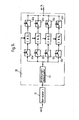
- the useful signal also affects noise, spectral components from neighboring frequency bands and simultaneous signals from other cells. Therefore, powerful signal processing in the receiver is one of the essential basics for the function kidneys of the system. 11 therefore shows the unit provided in the receiver for recovering the transmitted signal.
- the signal arrives at the receiver 8 at 17 correlators 31 when m is 16 for the code character according to FIG. 8, which are also controlled by a code generator 37.
- 17 correlators 31 one serves to synchronize the time slots and is required for the sequential control 32 of the time slots.
- the other 16 correlators 31 compare the received signal with the 16 code words of the 16-valued alphabet. Adjacent cells can use a different set of code words to differentiate between them. If this is required because of strong signals with long detours of more than 240 m, the code of this alphabet can change pseudo-statistically from one to the other 4-bit group.
- the correlators 31 are followed by 16 detectors 33 which recognize maxima in the autocorrelation function.
- a subsequent decision stage 34 selects the largest of all recognized maxima and defines the code word assigned to the corresponding correlator as the character that is sent with the highest probability.
- a downstream converter 35 generates the associated 4-bit group and feeds it to the buffer. This delivers the signals received during a time slot at its output with a continuous stream of 64 kbit / s.
- the mobile station converts the digital via an analog to an acoustic signal, while the stationary station converts the digital signs and, when forwarded via an optical fiber, converts them electrically / optically.
- the correlators are scanned to recover the transmitted character at the time of the largest correlation peak in the synchronization correlator.
- Detour signals in multipath reception result in further correlation peaks which are not used.
- the transmission quality is increased. Because of the increased effort involved, it is also conceivable to drive this effort only at fixed stations and only there at those in particularly critical areas. At the same time, the transmission power of these stations should be higher than that of the moving stations in order to achieve a quality that is balanced for both transmission directions.
- FIG. 12 shows a block diagram of a circuit for acquiring all correlation peaks of the synchronization preamble.
- the synchronization preamble passes from the receiver 8 to two correlators 31a and 31b connected in series for synchronization.
- the first correlator 31a simultaneously serves as Verzögerungslei - processing for the second correlator 31b, and both are connected to the partially illustrated flow control 32nd
- the correlation result of the first correlator 31a reaches an envelope demodulator 38a, which is followed by a maximum detector 39 and a reduction stage 40.
- the correlation result of the second correlator 31b reaches an envelope demodulator 38b.
- the outputs of the envelope curve demodulators are connected to a comparison and selection stage 41, which is followed by a further maximum detector 42.
- the arrival times ti can be taken from relevant detour signals, also called paths, and are available for the reception of the characters.
- the multi-path profile obtained in this way is shown in the course of the output voltage of the correlator for synchronization.
- the delay time of the correlator 31a must be chosen so long that the correlation result of the strongest path is available when the output signals of the correlator 31b are available for comparison in the comparison and selection stage 41.
- a threshold value for the comparison and selection stage 41 is derived from the correlation result of the strongest path. The threshold value serves to suppress correlation peaks in the noise or a little above it.
- the maximum detector 39 determines the absolute maximum of the correlation peaks, while the maximum detector 42, to which the reception time is also fed, determines the arrival times of the peaks exceeding the threshold value.
- the reduction stage 40 forms from the level of the strongest path the threshold value with which the multi-way profile is compared in the comparison and selection stage.
- the correlator 31 is connected to the receiver 8 and its output is connected to the sequential control 32 shown in part.
- a circuit 43, controlled by the maximum detector 39, for connecting the second synchronization preamble to the comparison and selection stage 41 is connected to the envelope curve demodulator 38.
- the absolute maximum of the multi-way profile and the threshold value are determined.
- the arrival times of the relevant paths are then determined from the correlation of the second synchronization preamble. Since the correlator and the envelope curve demodulator are used twice in succession, the effort is less compared to the circuit according to FIG. 12. The evaluation times required are the same in both circuits.
- FIG. 14 shows the block diagram of a detector 33 for multiple sampling of the characters received.
- Correlator 31 sends its signal to an envelope demodulator 44, to which four series connections of a switch 45a-d with an integrator with zeroing ID 1-4 and a further switch 46a-d are connected in parallel.
- m 16 and the duration of a code bit is 100 ns.
- the drawing time is 1.6 ps and the integration time is 6.4 ps.
- the switches 45 and 46 are controlled by the sequence control and are used for the correct transfer of the correlation results to the integrators and for the transfer of the integration results to the decision stage 34.
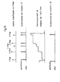
- the sequence of operations at the integrators with zeroing is shown in FIGS. 15 and 16 Diagrams shown.
- the cycle of each of the four series connections shown extends over a period of four m-valued code characters. The cycles are offset by one character each.
- each integrator is set to zero.
- the switch 45 is closed for a short time. This will add up the correlation results.
- the switch 46 closes the transfer of the integration result to decision stage 34.
- Decision stage 34 selects the largest of the M simultaneously incoming values and thus estimates the character sent.
- Each path supplies successive characters with the duration m ⁇ ⁇ .
- m means the code bit number of the code character and ⁇ the duration of a code bit.
- multi-path profiles in mobile radio extend up to 6 ps, in extreme cases up to about 10 ps. Since one integrator per correlator can be occupied by approximately 6 p s, further integrators must be available for the characters that have arrived in the meantime.
- the first integrator starts at to, the second at to + 1.6 ⁇ s, the third at to + 3.2 ps and the fourth at to + 4.8 ps.
- the first integrator is then available again at the time of to + 6.4 ps.
- the integrators can also be used to carry out an amplitude weighting.
- the integrators are provided with, for example, several discretely graded integration time constants.
- the simplest type of amplitude weighting is to only integrate the results of those paths that are roughly the same, and thereby not to change the integration time constant.
- Whether the correlators are scanned for the characters or not can be set by the level of the threshold value in the sequence control.
- threshold is very high, only one sample is taken at the maximum correlation peak. With a lowered threshold, a multiple sampling is carried out depending on the correlation peaks that occur.
Landscapes
- Engineering & Computer Science (AREA)
- Computer Networks & Wireless Communication (AREA)
- Signal Processing (AREA)
- Mobile Radio Communication Systems (AREA)
Applications Claiming Priority (4)
| Application Number | Priority Date | Filing Date | Title |
|---|---|---|---|
| DE19813118018 DE3118018A1 (de) | 1981-05-07 | 1981-05-07 | Nachrichtenuebertragungssystem |
| DE3118018 | 1981-05-07 | ||
| DE19813139408 DE3139408A1 (de) | 1981-10-03 | 1981-10-03 | Nachrichtenuebertragungssystem |
| DE3139408 | 1981-10-03 |
Publications (2)
| Publication Number | Publication Date |
|---|---|
| EP0064686A1 true EP0064686A1 (fr) | 1982-11-17 |
| EP0064686B1 EP0064686B1 (fr) | 1985-07-31 |
Family
ID=25793077
Family Applications (1)
| Application Number | Title | Priority Date | Filing Date |
|---|---|---|---|
| EP82103692A Expired EP0064686B1 (fr) | 1981-05-07 | 1982-04-30 | Système de transmission de messages |
Country Status (2)
| Country | Link |
|---|---|
| EP (1) | EP0064686B1 (fr) |
| DE (1) | DE3265045D1 (fr) |
Cited By (19)
| Publication number | Priority date | Publication date | Assignee | Title |
|---|---|---|---|---|
| EP0115330A2 (fr) * | 1983-01-28 | 1984-08-08 | Alcatel N.V. | Appareil de réception |
| GB2140254A (en) * | 1980-11-21 | 1984-11-21 | Western Electric Co | Mobile radio system |
| EP0150399A2 (fr) * | 1984-01-28 | 1985-08-07 | Licentia Patent-Verwaltungs-GmbH | Système radiotéléphonique numérique cellulaire avec multiplexage à division de temps |
| EP0151279A1 (fr) * | 1984-02-03 | 1985-08-14 | Licentia Patent-Verwaltungs-GmbH | Récepteur pour système cellulaire numérique en multiplexage de temps |
| EP0151281A1 (fr) * | 1984-02-03 | 1985-08-14 | Licentia Patent-Verwaltungs-GmbH | Système cellulaire numérique en multiplexage de temps |
| EP0151280A1 (fr) * | 1984-02-03 | 1985-08-14 | Licentia Patent-Verwaltungs-GmbH | Procédé en multiplexage de temps pour un système cellulaire numérique |
| GB2153188A (en) * | 1984-01-18 | 1985-08-14 | Communications Patents Ltd | Communications system |
| EP0156335A2 (fr) * | 1984-03-24 | 1985-10-02 | Alcatel SEL Aktiengesellschaft | Système de transmission d'informations |
| EP0171525A2 (fr) * | 1984-06-27 | 1986-02-19 | Alcatel SEL Aktiengesellschaft | Système de radiotéléphonie mobile |
| EP0188836A2 (fr) * | 1984-12-22 | 1986-07-30 | Philips Patentverwaltung GmbH | Méthode et dispositif pour la transmission d'informations dans un système numérique de radio-transmission |
| DE3522859A1 (de) * | 1985-06-26 | 1987-01-08 | Siemens Ag | Schmalbandiges rbertragungsverfahren fuer ein digitales mobiles funksystem |
| EP0211460A2 (fr) * | 1985-07-31 | 1987-02-25 | Philips Patentverwaltung GmbH | Procédé de radio-transmission numérique |
| DE3337646A1 (de) * | 1983-10-17 | 1987-02-26 | Licentia Gmbh | Funknetz mit einer vielzahl von mobilen stationen |
| EP0241954A2 (fr) * | 1986-03-08 | 1987-10-21 | Philips Patentverwaltung GmbH | Système numérique de radio-transmission et appareil radiomobile d'abonné pour ce système numérique de radio-transmission. |
| GB2195869A (en) * | 1986-09-05 | 1988-04-13 | Mitsubishi Electric Corp | Cellular mobile radio communication system with repeater station grid |
| US5119375A (en) * | 1985-03-20 | 1992-06-02 | International Mobile Machines Corp. | Subscriber RF telephone system for providing multiple speech and/or data signals simultaneously over either a single or a plurality of RF channels |
| EP0613276A1 (fr) * | 1993-02-26 | 1994-08-31 | ORBITEL MOBILE COMMUNICATIONS LIMITED (Reg. no. 2515004) | Système de synchronisation de plusieurs émetteurs radio |
| EP0656735A2 (fr) * | 1993-12-02 | 1995-06-07 | AT&T Corp. | Téléphone portable bimodal |
| FR2729027A1 (fr) * | 1995-01-02 | 1996-07-05 | Alcatel Mobile Comm France | Procede et dispositif pour allouer des voies de communication a des mobiles proches et lointains dans un systeme de radiocommunication cellulaire amrt, notamment un systeme gsm |
Families Citing this family (1)
| Publication number | Priority date | Publication date | Assignee | Title |
|---|---|---|---|---|
| US5546383A (en) | 1993-09-30 | 1996-08-13 | Cooley; David M. | Modularly clustered radiotelephone system |
Citations (6)
| Publication number | Priority date | Publication date | Assignee | Title |
|---|---|---|---|---|
| US3532985A (en) * | 1968-03-13 | 1970-10-06 | Nasa | Time division radio relay synchronizing system using different sync code words for "in sync" and "out of sync" conditions |
| US3908088A (en) * | 1974-05-22 | 1975-09-23 | Us Army | Time division multiple access communications system |
| DE2536452A1 (de) * | 1975-08-16 | 1977-02-24 | Licentia Gmbh | Verfahren zur teilnehmersuche in einem funkuebertragungssystem |
| US4129749A (en) * | 1976-06-24 | 1978-12-12 | Goldman Stephen R | Radio telephone communications system |
| US4222115A (en) * | 1978-03-13 | 1980-09-09 | Purdue Research Foundation | Spread spectrum apparatus for cellular mobile communication systems |
| US4301530A (en) * | 1978-12-18 | 1981-11-17 | The United States Of America As Represented By The Secretary Of The Army | Orthogonal spread spectrum time division multiple accessing mobile subscriber access system |
-
1982
- 1982-04-30 DE DE8282103692T patent/DE3265045D1/de not_active Expired
- 1982-04-30 EP EP82103692A patent/EP0064686B1/fr not_active Expired
Patent Citations (6)
| Publication number | Priority date | Publication date | Assignee | Title |
|---|---|---|---|---|
| US3532985A (en) * | 1968-03-13 | 1970-10-06 | Nasa | Time division radio relay synchronizing system using different sync code words for "in sync" and "out of sync" conditions |
| US3908088A (en) * | 1974-05-22 | 1975-09-23 | Us Army | Time division multiple access communications system |
| DE2536452A1 (de) * | 1975-08-16 | 1977-02-24 | Licentia Gmbh | Verfahren zur teilnehmersuche in einem funkuebertragungssystem |
| US4129749A (en) * | 1976-06-24 | 1978-12-12 | Goldman Stephen R | Radio telephone communications system |
| US4222115A (en) * | 1978-03-13 | 1980-09-09 | Purdue Research Foundation | Spread spectrum apparatus for cellular mobile communication systems |
| US4301530A (en) * | 1978-12-18 | 1981-11-17 | The United States Of America As Represented By The Secretary Of The Army | Orthogonal spread spectrum time division multiple accessing mobile subscriber access system |
Non-Patent Citations (2)
| Title |
|---|
| INTERNATIONAL CONFERENCE ON COMMUNICATIONS, Band 3 von 4, 14.-18. Juni 1981, Conference Record, Seiten 44.4.1 bis 44.4.5, New York, USA * |
| NACHRICHTENTECHNISCHE ZEITSCHRIFT, Band 27, Nr. 7, Juli 1974, Seiten 253-259, Berlin, DE. * |
Cited By (31)
| Publication number | Priority date | Publication date | Assignee | Title |
|---|---|---|---|---|
| GB2140254A (en) * | 1980-11-21 | 1984-11-21 | Western Electric Co | Mobile radio system |
| EP0115330A2 (fr) * | 1983-01-28 | 1984-08-08 | Alcatel N.V. | Appareil de réception |
| EP0115330A3 (fr) * | 1983-01-28 | 1987-09-09 | Alcatel N.V. | Appareil de réception |
| DE3337646A1 (de) * | 1983-10-17 | 1987-02-26 | Licentia Gmbh | Funknetz mit einer vielzahl von mobilen stationen |
| DE3337646C2 (de) * | 1983-10-17 | 2001-07-05 | Daimlerchrysler Aerospace Ag | Funknetz mit einer Vielzahl von mobilen Stationen |
| GB2153188A (en) * | 1984-01-18 | 1985-08-14 | Communications Patents Ltd | Communications system |
| EP0150399A2 (fr) * | 1984-01-28 | 1985-08-07 | Licentia Patent-Verwaltungs-GmbH | Système radiotéléphonique numérique cellulaire avec multiplexage à division de temps |
| EP0150399A3 (en) * | 1984-01-28 | 1987-05-06 | Licentia Patent-Verwaltungs-Gmbh | Cellular digital radio telephone system with time division multiplex |
| EP0151279A1 (fr) * | 1984-02-03 | 1985-08-14 | Licentia Patent-Verwaltungs-GmbH | Récepteur pour système cellulaire numérique en multiplexage de temps |
| EP0151281A1 (fr) * | 1984-02-03 | 1985-08-14 | Licentia Patent-Verwaltungs-GmbH | Système cellulaire numérique en multiplexage de temps |
| EP0151280A1 (fr) * | 1984-02-03 | 1985-08-14 | Licentia Patent-Verwaltungs-GmbH | Procédé en multiplexage de temps pour un système cellulaire numérique |
| EP0156335A2 (fr) * | 1984-03-24 | 1985-10-02 | Alcatel SEL Aktiengesellschaft | Système de transmission d'informations |
| EP0156335A3 (fr) * | 1984-03-24 | 1987-11-04 | Alcatel SEL Aktiengesellschaft | Système de transmission d'informations |
| EP0171525A2 (fr) * | 1984-06-27 | 1986-02-19 | Alcatel SEL Aktiengesellschaft | Système de radiotéléphonie mobile |
| EP0171525A3 (fr) * | 1984-06-27 | 1988-07-13 | Alcatel SEL Aktiengesellschaft | Système de radiotéléphonie mobile |
| EP0188836A2 (fr) * | 1984-12-22 | 1986-07-30 | Philips Patentverwaltung GmbH | Méthode et dispositif pour la transmission d'informations dans un système numérique de radio-transmission |
| EP0188836A3 (en) * | 1984-12-22 | 1988-10-12 | Philips Patentverwaltung Gmbh | Method and device for information transmission in a digital radio transmission system |
| US5119375A (en) * | 1985-03-20 | 1992-06-02 | International Mobile Machines Corp. | Subscriber RF telephone system for providing multiple speech and/or data signals simultaneously over either a single or a plurality of RF channels |
| DE3609395C3 (de) * | 1985-03-20 | 1999-04-08 | Interdigital Tech Corp | Digitales Telefonsystem |
| DE3522859A1 (de) * | 1985-06-26 | 1987-01-08 | Siemens Ag | Schmalbandiges rbertragungsverfahren fuer ein digitales mobiles funksystem |
| EP0211460A3 (en) * | 1985-07-31 | 1989-03-15 | Philips Patentverwaltung Gmbh | Digital radio transmission system |
| EP0211460A2 (fr) * | 1985-07-31 | 1987-02-25 | Philips Patentverwaltung GmbH | Procédé de radio-transmission numérique |
| EP0241954A3 (en) * | 1986-03-08 | 1989-04-19 | Philips Patentverwaltung Gmbh | Method and circuit arrangement for switching a radio communication through to another radio cell of a digital radio transmission system |
| EP0241954A2 (fr) * | 1986-03-08 | 1987-10-21 | Philips Patentverwaltung GmbH | Système numérique de radio-transmission et appareil radiomobile d'abonné pour ce système numérique de radio-transmission. |
| GB2195869B (en) * | 1986-09-05 | 1990-11-14 | Mitsubishi Electric Corp | A mobile radio communication system with repeater station grid |
| GB2195869A (en) * | 1986-09-05 | 1988-04-13 | Mitsubishi Electric Corp | Cellular mobile radio communication system with repeater station grid |
| EP0613276A1 (fr) * | 1993-02-26 | 1994-08-31 | ORBITEL MOBILE COMMUNICATIONS LIMITED (Reg. no. 2515004) | Système de synchronisation de plusieurs émetteurs radio |
| EP0656735A2 (fr) * | 1993-12-02 | 1995-06-07 | AT&T Corp. | Téléphone portable bimodal |
| EP0656735A3 (fr) * | 1993-12-02 | 1997-12-29 | AT&T Corp. | Téléphone portable bimodal |
| FR2729027A1 (fr) * | 1995-01-02 | 1996-07-05 | Alcatel Mobile Comm France | Procede et dispositif pour allouer des voies de communication a des mobiles proches et lointains dans un systeme de radiocommunication cellulaire amrt, notamment un systeme gsm |
| EP0721290A1 (fr) * | 1995-01-02 | 1996-07-10 | Alcatel Cit | Procédé et dispositif pour allouer des voies de communication à des mobiles proches et lointains dans un système de radiocommunication cellulaire AMRT, notamment un système GSM |
Also Published As
| Publication number | Publication date |
|---|---|
| DE3265045D1 (en) | 1985-09-05 |
| EP0064686B1 (fr) | 1985-07-31 |
Similar Documents
| Publication | Publication Date | Title |
|---|---|---|
| EP0064686B1 (fr) | Système de transmission de messages | |
| EP0211460B1 (fr) | Procédé de radio-transmission numérique | |
| DE4293440C2 (de) | Verfahren zur Sendesynchronisation und Kommunikationssystem | |
| EP0210700B1 (fr) | Système de radio-transmission numérique avec canal de service central associé à la communication dans la trame multiplexée dans le temps | |
| EP0241954B1 (fr) | Système numérique de radio-transmission et appareil radiomobile d'abonné pour ce système numérique de radio-transmission. | |
| EP0210698B1 (fr) | Système de radio-transmission avec durée variable des intervalles temporaires d'une trame multiplex dans le temps | |
| EP0196723B1 (fr) | Méthode et circuit pour la synchronisation des dispositifs de réception dans un système de transmission multiplex numérique | |
| DE69730107T2 (de) | System und Verfahren zum Erzeugen einer spreizspektrum-phasenmodulierten Wellenform | |
| EP0188836B1 (fr) | Méthode et dispositif pour la transmission d'informations dans un système numérique de radio-transmission | |
| DE4292564C2 (de) | Verfahren zum Aufbau einer Funkverbindung sowie Basisstation und Teilnehmereinheit hierzu | |
| DE3118018C2 (fr) | ||
| DE69534223T2 (de) | Verfahren und vorrichtung zur funkkommunikation | |
| EP1027788B1 (fr) | Procede et dispositif de transfert de donnees par une interface radio dans un systeme de radiocommunications | |
| DE1802614A1 (de) | In Zonen eingeteilte Mobil-Funkfernsprechanlage | |
| EP0151280A1 (fr) | Procédé en multiplexage de temps pour un système cellulaire numérique | |
| EP1013007A1 (fr) | Dispositif d'emission et de reception pour l'amplification entre des stations fixes et des stations mobiles avec detection du canal radio | |
| DE60125002T2 (de) | Verfahren zur übertragung eines Synchronisationssignals in einem TDD-System | |
| DE19713164A1 (de) | Funkkommunikationssystem und Funkbasisstationsgerät | |
| DE4333396C2 (de) | Drahtloses CDMA-Informationsübertragungssystem | |
| DE19907502C2 (de) | Verfahren zur Kanalschätzung | |
| DE19851309C1 (de) | Verfahren zur Datenübertragung in einem Funk-Kommunikationssystem über eine Funkschnittstelle zwischen einer Basisstation und Teilnehmerstation | |
| DE3139408C2 (fr) | ||
| EP1508212B9 (fr) | Procede et dispositif de transmission optique de donnees | |
| DE19836888A1 (de) | Verfahren und Vorrichtung für ein voll duplexfähigesFunkübertragungssystem mit CDMA-Zugriff | |
| DE2364374C3 (de) | Fernmeldeanlage mit Relaisstationen und ortsfesten und beweglichen Teilnehmerstellen |
Legal Events
| Date | Code | Title | Description |
|---|---|---|---|
| PUAI | Public reference made under article 153(3) epc to a published international application that has entered the european phase |
Free format text: ORIGINAL CODE: 0009012 |
|
| AK | Designated contracting states |
Designated state(s): CH DE FR NL |
|
| 17P | Request for examination filed |
Effective date: 19821221 |
|
| GRAA | (expected) grant |
Free format text: ORIGINAL CODE: 0009210 |
|
| AK | Designated contracting states |
Designated state(s): CH DE FR LI NL |
|
| REF | Corresponds to: |
Ref document number: 3265045 Country of ref document: DE Date of ref document: 19850905 |
|
| ET | Fr: translation filed | ||
| PLBI | Opposition filed |
Free format text: ORIGINAL CODE: 0009260 |
|
| 26 | Opposition filed |
Opponent name: PHILIPS PATENTVERWALTUNG GMBH Effective date: 19860418 |
|
| NLR1 | Nl: opposition has been filed with the epo |
Opponent name: PHILIPS PATENTVERWALTUNG GMBH |
|
| PGFP | Annual fee paid to national office [announced via postgrant information from national office to epo] |
Ref country code: NL Payment date: 19870430 Year of fee payment: 6 |
|
| REG | Reference to a national code |
Ref country code: CH Ref legal event code: PUE Owner name: ALCATEL N.V. |
|
| REG | Reference to a national code |
Ref country code: FR Ref legal event code: TP |
|
| NLS | Nl: assignments of ep-patents |
Owner name: ALCATEL N.V. TE AMSTERDAM. |
|
| RAP2 | Party data changed (patent owner data changed or rights of a patent transferred) |
Owner name: STANDARD ELEKTRIK LORENZ AKTIENGESELLSCHAFT Owner name: ALCATEL N.V. |
|
| RDAG | Patent revoked |
Free format text: ORIGINAL CODE: 0009271 |
|
| STAA | Information on the status of an ep patent application or granted ep patent |
Free format text: STATUS: PATENT REVOKED |
|
| 27W | Patent revoked |
Effective date: 19890406 |
|
| REG | Reference to a national code |
Ref country code: CH Ref legal event code: PL |
|
| NLR2 | Nl: decision of opposition | ||
| APAH | Appeal reference modified |
Free format text: ORIGINAL CODE: EPIDOSCREFNO |