EP0061164B1 - Tubular metering device for dispensing identical metered amounts of fluid - Google Patents
Tubular metering device for dispensing identical metered amounts of fluid Download PDFInfo
- Publication number
- EP0061164B1 EP0061164B1 EP82102249A EP82102249A EP0061164B1 EP 0061164 B1 EP0061164 B1 EP 0061164B1 EP 82102249 A EP82102249 A EP 82102249A EP 82102249 A EP82102249 A EP 82102249A EP 0061164 B1 EP0061164 B1 EP 0061164B1
- Authority
- EP
- European Patent Office
- Prior art keywords
- passage
- opening
- volume
- liquid
- dosage device
- Prior art date
- Legal status (The legal status is an assumption and is not a legal conclusion. Google has not performed a legal analysis and makes no representation as to the accuracy of the status listed.)
- Expired
Links
- 239000012530 fluid Substances 0.000 title 1
- 239000007788 liquid Substances 0.000 claims abstract description 90
- 238000005192 partition Methods 0.000 claims abstract description 9
- 238000005273 aeration Methods 0.000 claims 1
- 238000009423 ventilation Methods 0.000 description 5
- XLYOFNOQVPJJNP-UHFFFAOYSA-N water Substances O XLYOFNOQVPJJNP-UHFFFAOYSA-N 0.000 description 4
- 239000004033 plastic Substances 0.000 description 3
- 238000010276 construction Methods 0.000 description 2
- 238000001746 injection moulding Methods 0.000 description 2
- 238000000034 method Methods 0.000 description 2
- 230000002093 peripheral effect Effects 0.000 description 2
- 230000003014 reinforcing effect Effects 0.000 description 2
- 230000007704 transition Effects 0.000 description 2
- 239000004743 Polypropylene Substances 0.000 description 1
- 238000004026 adhesive bonding Methods 0.000 description 1
- 230000000694 effects Effects 0.000 description 1
- -1 polypropylene Polymers 0.000 description 1
- 229920001155 polypropylene Polymers 0.000 description 1
- 230000000717 retained effect Effects 0.000 description 1
- 238000007142 ring opening reaction Methods 0.000 description 1
- 238000007789 sealing Methods 0.000 description 1
- 238000003466 welding Methods 0.000 description 1
Images

Classifications
-
- G—PHYSICS
- G01—MEASURING; TESTING
- G01F—MEASURING VOLUME, VOLUME FLOW, MASS FLOW OR LIQUID LEVEL; METERING BY VOLUME
- G01F11/00—Apparatus requiring external operation adapted at each repeated and identical operation to measure and separate a predetermined volume of fluid or fluent solid material from a supply or container, without regard to weight, and to deliver it
- G01F11/10—Apparatus requiring external operation adapted at each repeated and identical operation to measure and separate a predetermined volume of fluid or fluent solid material from a supply or container, without regard to weight, and to deliver it with measuring chambers moved during operation
- G01F11/26—Apparatus requiring external operation adapted at each repeated and identical operation to measure and separate a predetermined volume of fluid or fluent solid material from a supply or container, without regard to weight, and to deliver it with measuring chambers moved during operation wherein the measuring chamber is filled and emptied by tilting or inverting the supply vessel, e.g. bottle-emptying apparatus
- G01F11/262—Apparatus requiring external operation adapted at each repeated and identical operation to measure and separate a predetermined volume of fluid or fluent solid material from a supply or container, without regard to weight, and to deliver it with measuring chambers moved during operation wherein the measuring chamber is filled and emptied by tilting or inverting the supply vessel, e.g. bottle-emptying apparatus for liquid or semi-liquid
Definitions
- the invention relates to a tubular metering device for dispensing quantities of liquid of the same volume from liquid containers, which are provided with a dispensing opening into which the metering device can be inserted, so that the dispensing opening is closed by the metering device sealed against the container wall, with one in it Inner dosing channel extending in the axial direction, open to the outer end with respect to the liquid container, and a dosing channel, which extends in the interior in the axial direction and closed to the outer end, are separated from one another by a dividing wall which is at a distance from the inner end of the dosing device occluding bottom ends, so that between the bottom and the end of the partition a dosing channel and the pouring channel connecting collecting space is formed, the volume of which is at least equal to the volume to be dosed, the dosing channel corresponding to two at an axial distance hend the volume to be metered openings is connected to the interior of the container and a collecting space is formed in the metering channel between the
- the two openings connecting the metering channel to the interior of the liquid container are located in the side wall of the metering device, specifically the one opening directly on the transverse wall closing the metering channel at the outer end and the other opening at a corresponding axial distance from the first opening, so that the two openings lie on a straight line parallel to the longitudinal axis of the metering device.
- liquid flows from the interior of the container through the axially outermost opening in the wall of the metering channel into the latter until the liquid level in the metering channel has risen so high is that, when the liquid container is upside down, it closes the second opening. In this state, air can no longer get into the interior of the liquid container and the volume of liquid to be dispensed has been reached.
- the amount of free liquid is thus different in size, whereby this free liquid cannot flow out of the metering channel, so that actually only half of the theoretically possible amount of free liquid gets into the metering channel and thereby the other half is retained in the interior of the liquid container.
- the free liquid exiting into the metering channel in the known metering device beyond the desired volume has the effect that a certain negative pressure is created in the interior of the liquid container. If the liquid container is then tilted back into its normal position, the free liquid which has entered the dosing channel is sucked back into the interior of the container through the second opening in the wall of the dosing channel during this process due to the negative pressure in the liquid container, while this is due to the distance between the two Openings in the wall of the metering channel reach certain liquid volumes in the collecting space between the end of the partition and the bottom of the metering device. From here, the liquid can then be dispensed through the pouring channel by tilting the liquid container, and with a corresponding tilting, a new liquid volume of the desired size will also enter the metering channel at the same time.
- the known metering device has the disadvantage of relatively great inaccuracy in the determination of the liquid volume to be dispensed, because the liquid level in the metering channel can be different in that the user brings the liquid container to fill the metering channel in different inclination positions, the desired volume being obtained exactly when the Liquid container is turned upside down in such a way that the longitudinal axis of the metering channel is perpendicular.
- the metered liquid volume is either larger or smaller than desired because the liquid closes both openings in the wall of the metering channel, but the liquid level corresponds to the deviation of the longitudinal axis of the metering channel from the vertical with respect to the longitudinal axis is inclined. i.e. the deviation of the liquid level from a plane perpendicular to the longitudinal axis of the metering chamber resulting from the inclination causes a difference in the liquid volume from the volume to be dispensed per se.
- a metering device of the type mentioned at the outset is designed in such a way that the opening furthest from the outer end is formed by the opening of a channel extending through the bottom wall into the metering channel, the opening preferably being arranged coaxially to the longitudinal axis of the metering channel is.
- the position of the size of the volume to be dispensed in the metering channel is no longer in the side wall of the metering channel, but rather in the center thereof, preferably on its longitudinal axis, if the longitudinal axis of the metering channel deviates from the vertical during Filling the metering channel as in the known metering device a liquid level deviating from the vertical plane to the longitudinal axis of the metering channel does occur, but this liquid level will lie on one side of the mouth opening below and on the opposite side of the mouth opening above it, ie the too low and the too high fill level with respect to the mouth opening compensate each other, in particular when the mouth opening is arranged coaxially to the longitudinal axis of the metering channel, the metering channel having, for example, a circular cross section. In this way, the inevitable deviations from the predetermined liquid volume in the known metering device are avoided in the simplest way by the metering device according to the invention.
- the wall of the channel can be formed in one piece with the bottom wall.
- the mouth opening of the channel should be as small as possible for a liquid of a certain viscosity, so that when the liquid is transported from the metering channel into the collecting space, the so-called free liquid is sucked back into the interior of the liquid container, but no other liquid gets into the container interior, and thus the Deviation from the size of the liquid volume to be dispensed is as small as possible with an inclination with respect to the vertical.
- the channel preferably tapers towards the mouth opening, so that simple demolding is possible when manufactured by injection molding.
- the metering device according to the invention does not always work reliably or is relatively large Time is required to fill the dosing channel to the desired height.
- the inlet opening of the channel opposite the mouth opening can have a diameter which is 1/2 to 1/5, preferably 1/3 to 1/4, of the diameter of the region of the channel adjoining the inlet opening.
- the surface of the wall area having the inlet opening located outside the channel can be in the same plane as the surface of the bottom wall facing away from the orifice opening or a larger distance from it Have mouth opening as this area of the bottom wall.
- the inner end of the wall surrounding the metering channel can be drawn in towards the channel, i.e. the connection opening between the metering channel and the collecting space can have an opening cross-section that is reduced compared to the cross-section of these two areas.
- a liquid is to be portioned whose viscosity is greater than that of water, it may be expedient to provide ventilation openings between the mouth opening and the inner end of the wall surrounding the metering channel. Air can pass through these ventilation openings when filling the collecting space, the dimensions of the annular space between the inner end of the wall surrounding the dosing channel and the wall of the channel not being sufficient for the passage thereof.
- a plurality of openings distributed on the periphery of the ' metering channel and adjacent to its outer end can be provided.
- the metering device shown has a tubular outer body 3, which is pressed into the neck of a bottle 1, so that the outer end region 3 'of the outer body 3 lies sealingly against the inner wall of the neck, while a adjoining this end region, outwardly directed annular shoulder 4 prevents the metering device from being pressed too far into the bottle 1.
- the bottle 1 is closed with a screw cap 2, which, however, is removed for using the metering device.
- a tubular inner body 14 with a circular cross section which has an outwardly directed annular shoulder 14 ′′, which is interrupted only in the region of the pouring channel 13 to be described later, and which on an inwardly directed, only in the region of the Descriptive metering channel 13 is interrupted annular shoulder 4 'of the outer body 3, whereby the axial position of the inner body 14 is determined with respect to the outer body 3.
- the inner body 14 is held by contact with the outer body 3, the peripheral wall between the radially extending transition regions 9 radially is offset inwards and forms contact areas 3 "(FIG. 3) which are in engagement with the outer surface of the inner body 14 and hold it in its coaxial position with respect to the outer body 3.
- the peripheral wall of the outer body 3 merges at the inner end into a bottom wall 10, from which a frustoconical wall section 11 extends coaxially to the longitudinal axis of the outer body 3 and inner body 14 in the direction of the bottle opening or the outer end of the metering device and inside the inner body 14 ends.
- the wall section 11 forms a channel 18 in its interior, which has an opening 19 at its end located in the inner body 14 and connects the interior of the bottle 1 with the interior of the inner body 14.
- the inner end region 14 'of the inner body 14 runs in the shape of a truncated cone, so that an annular space 15 surrounding the wall section 11 is formed at the inner end of the inner body 14.
- a sealing plug 6 is inserted, which with an interrupted only in the area of the pouring channel 13 to be described, outwardly directed annular shoulder 7 on the annular shoulder 14 "and behind an inward is directed and is thus held in position.
- the stopper 6 is formed by radially extending reinforcing ribs 8 and reinforcing regions 6 'running in the circumferential direction so that it does not deform, but rather the entire metering device, except the dosing channel 13 to be described, reliably seals at the outer end.
- openings 17 are provided in the walls of the outer body 3 and inner body 14, which connect the interior of the bottle 1 to the interior of the inner body 14. There are three openings 17, which are evenly distributed on the circumference and each lie in the circumferential direction at the same point as the contact areas 3 "(FIG. 3).
- the interior of the inner body 14 forms a metering channel 16, and when the bottle 1 is turned over to fill this metering channel with the screw cap 2 unscrewed, liquid flows through the openings 17 of the metering channel 16 into the latter until the liquid level reaches the orifice 19 arranged coaxially to the metering channel 16 and closes it.
- the mouth opening 19 is closed, air can no longer get into the interior of the bottle 1, and only the so-called free liquid flows through the openings 17 into the metering channel 16, which raises the liquid level in such a way that it is in a region between the mouth opening 19 and Ring opening 15 is located.
- the volume of this area must of course be chosen so that it absorbs this free amount of liquid, which is half of the theoretically exiting free amount of liquid that would escape if the free liquid could flow off without hindrance.
- the bottle 1 After filling the dosing channel 16, the bottle 1 is turned back into the position shown in FIG. 1, and the liquid from the dosing channel 16 flows through the annular space 15 into the collecting space 12, namely the volume of liquid flowing into this collecting space, which is between the Had accumulated inner surface of the plug 6 or the outer end of the openings 17 and the mouth opening 19, while the amount of free liquid located between the mouth opening 19 and the annular space 15 is sucked back into this interior space through the mouth opening 19 due to the negative pressure in the interior of the bottle 1 .
- the volume of liquid which is determined in this way in a reproducible manner and which is located in the collecting space 12 can then be tilted again by the bottle 1 through the pouring channel 13 which is open to the outside and which, as can be seen in particular from FIG Circumferential wall of the outer body 3 and adjoining transition areas 9 are given.
- the metering channel 16 already fills again through the openings 17, so that a predetermined volume of liquid is brought into the metering channel again during the pouring process.
- the central position of the orifice 1.3 with respect to the metering channel 16 ensures that if the longitudinal axis of the metering channel 16 deviates from the vertical while this channel is being filled, there is no significant deviation of the volume taken up from the predetermined volume.
- the resulting liquid level shown in broken lines, deviates from the liquid level shown in broken lines when the metering channel 16 is in the vertical position such that more on one side and on the other less liquid is available on the other side, so the deviations of the two sides compensate each other. This compensation will occur the more precisely the smaller the opening 19 is, because then the liquid level shown in dashed lines, which closes the entire opening 19, runs at a very short distance from the center of the opening 19.
- the distribution of the openings 17 on the circumference of the outer body 3 and inner body 14 also ensures reliable metering when only relatively little liquid is left in the bottle, and that the distribution of the openings 17 also does makes it unnecessary to tilt the bottle along a predetermined plane, as would be necessary if only a single opening 17 was provided.
- the metering device consists of only three individual parts, the outer body 3, the inner body 14 and the stopper 6, all of which can be produced very easily by injection molding from plastic, such as polypropylene, and are simply pressed together for assembly and then pressed into the bottle need to be.
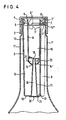
- FIG. 4 The basic construction of the dosing device shown in FIG. 4 corresponds to the dosing device according to FIGS. 1 to 3, and corresponding parts are therefore identified by the same reference numerals.
- This metering device is inserted into a bottle 1 'with an elongated neck, for example a plastic bottle with relatively easily deformable walls.
- the lower end of the channel 18 in the figure is closed with a plate 21 which is fastened to the lower surface of the wall 10, for example by welding or gluing.
- this plate there is an inlet opening 20 coaxially with respect to the channel 18, the diameter of which is approximately 1/4 of the diameter of the region of the channel 18 adjoining the plate, this region beginning in the drawing behind the input curvature of the channel 18.
- This narrowed inlet opening 20 of the channel 18 accelerates, as already mentioned above, the filling of the metering channel 16 when using the metering device in easily deformable containers and / or when metering liquids whose viscosity is greater than that of water.
- a further deviation of the metering device according to FIG. 4 compared to the metering device according to FIGS. 1 to 3 is that small ventilation openings 22 are provided in the wall 14 in the area between the mouth opening 19 of the channel 18 and the annular space 15. These ventilation openings facilitate the entry of air into the metering channel 16 when a liquid whose viscosity is greater than that of water flows out of the metering channel 16 into the collecting space 12. This accelerates the emptying of the metering channel, while in the absence of these ventilation openings due to the viscosity the liquid, the air could possibly not pass through the annular space 15 quickly enough.
Landscapes
- Physics & Mathematics (AREA)
- Fluid Mechanics (AREA)
- General Physics & Mathematics (AREA)
- Closures For Containers (AREA)
- Sampling And Sample Adjustment (AREA)
- Infusion, Injection, And Reservoir Apparatuses (AREA)
- Containers And Packaging Bodies Having A Special Means To Remove Contents (AREA)
Abstract
Description
Die Erfindung bezieht sich auf eine rohrförmige Dosiereinrichtung zur Abgabe von Flüssigkeitsmengen gleichen Volumens aus Flüssigkeitsbehältern, die mit einer Abgabeöffnung versehen sind, in die die Dosiereinrichtung einsteckbar ist, so daß die Abgabeöffnung von der gegen die Behälterwandung abgedichteten Dosiereinrichtung verschlossen wird, mit einem sich in ihrem Inneren in axialer Richtung erstreckenden, zum bezüglich des Flüssigkeitsbehälters äußeren Ende offenen Ausgießkanal und einem sich in ihrem Inneren in axialer Richtung erstreckenden, zum äußeren Ende hin geschlossenen Dosierkanal, die durch eine Trennwand voneinander getrennt sind, die im Abstand von dem das innere Ende der Dosiereinrichtung verschließenden Boden endet, so daß zwischen dem Boden und dem Trennwandende ein den Dosierkanal und den Ausgießkanal verbindender Sammelraum gebildet wird, dessen Volumen mindestens gleich dem zu dosierenden Volumen ist, wobei der Dosierkanal über zwei in einem axialen Abstand entsprechend dem zu dosierenden Volumen angeordnete Öffnungen mit dem Behälterinnenraum verbunden ist und im Dosierkanal zwischen der am weitesten von seinem äußeren Ende entfernten Öffnung und dem Trennwandende ein Auffangraum gebildet ist, dessen Volumen mindestens gleich dem Volumen der Hälfte der maximal auftretenden freien Flüssigkeit ist.The invention relates to a tubular metering device for dispensing quantities of liquid of the same volume from liquid containers, which are provided with a dispensing opening into which the metering device can be inserted, so that the dispensing opening is closed by the metering device sealed against the container wall, with one in it Inner dosing channel extending in the axial direction, open to the outer end with respect to the liquid container, and a dosing channel, which extends in the interior in the axial direction and closed to the outer end, are separated from one another by a dividing wall which is at a distance from the inner end of the dosing device occluding bottom ends, so that between the bottom and the end of the partition a dosing channel and the pouring channel connecting collecting space is formed, the volume of which is at least equal to the volume to be dosed, the dosing channel corresponding to two at an axial distance hend the volume to be metered openings is connected to the interior of the container and a collecting space is formed in the metering channel between the most distant from its outer end and the end of the partition, the volume of which is at least equal to the volume of half of the maximum free liquid occurring.
Bei einer bekannten Dosiereinrichtung dieser Art (DE-PS 1 202 672) befinden sich die beiden den Dosierkanal mit dem Innenraum des Flüssigkeitsbehälters verbindenden Öffnungen in der Seitenwand der Dosiereinrichtung, und zwar die eine Öffnung direkt anschließend an der den Dosierkanal am äußeren Ende verschließenden Querwand und die andere Öffnung im entsprechenden axialen Abstand von der ersten Öffnung, so daß die beiden Öffnungen auf einer parallel zur Längsachse der Dosiereinrichtung verlaufenden Geraden liegen.In a known metering device of this type (
Wird der Flüssigkeitsbehälter, der mittels der bekannten Dosiereinrichtung verschlossen ist, auf den Kopf gestellt, so fließt Flüssigkeit aus dem Innenraum des Behälters durch die axial am weitesten außen liegende Öffnung in der Wandung des Dosierkanals in diesen hinein, bis der Flüssigkeitsstand im Dosierkanal so hoch angestiegen ist, daß er, bei auf dem Kopf stehenden Flüssigkeitsbehälter, die zweite Öffnung verschließt. In diesem Zustand kann keine Luft mehr in den Innenraum des Flüssigkeitsbehälters gelangen, und das abzugebende Flüssigkeitsvolumen ist erreicht.If the liquid container, which is closed by means of the known metering device, is turned upside down, liquid flows from the interior of the container through the axially outermost opening in the wall of the metering channel into the latter until the liquid level in the metering channel has risen so high is that, when the liquid container is upside down, it closes the second opening. In this state, air can no longer get into the interior of the liquid container and the volume of liquid to be dispensed has been reached.
Allerdings tritt auch nach Verschließen der zweiten Öffnung durch die Flüssigkeit noch weitere Flüssigkeit aus dem Innenraum des Flüssigkeitsbehälters in den Dosierkanal ein, nämlich die sogenannte freie Flüssigkeit. Dies ist diejenige Flüssigkeitsmenge, die aus dem Flüssigkeitsbehälter ausfließen würde, wenn man den Behälter öffnen, jedoch den Eintritt von Luft in den Behälterinnenraum verhindern würde. Die Menge dieser sogenannten freien Flüssigkeit hängt unter anderem vom spezifischen Gewicht der Flüssigkeit, der Höhe der Flüssigkeitssäule und von der Luftmenge im Flüssigkeitsbehälter ab, die durch das Austreten der freien Flüssigkeit expandiert und dann unter einem Unterdruck steht. Je nach Grad der Füllung des Flüssigkeitsbehälters ist somit die Menge an freier Flüssigkeit unterschiedlich groß, wobei diese freie Flüssigkeit nicht aus dem Dosierkanal abfließen kann, so daß tatsächlich nur die Hälfte der theoretisch möglichen Menge an freier Flüssigkeit in den Dosierkanal gelangt und dadurch die andere Hälfte im Innenraum des Flüssigkeitsbehälters zurückgehalten wird.However, even after the second opening has been closed by the liquid, further liquid enters the dosing channel from the interior of the liquid container, namely the so-called free liquid. This is the amount of liquid that would flow out of the liquid container if the container was opened but would prevent air from entering the interior of the container. The amount of this so-called free liquid depends, among other things, on the specific weight of the liquid, the height of the liquid column and the amount of air in the liquid container, which expands when the free liquid emerges and is then under a vacuum. Depending on the degree of filling of the liquid container, the amount of free liquid is thus different in size, whereby this free liquid cannot flow out of the metering channel, so that actually only half of the theoretically possible amount of free liquid gets into the metering channel and thereby the other half is retained in the interior of the liquid container.
Die bei der bekannten Dosiereinrichtung über das gewünschte Volumen hinaus in den Dosierkanal austretende freie Flüssigkeit bewirkt, daß im Innenraum des Flüssigkeitsbehälters ein gewisser Unterdruck entsteht. Wird dann der Flüssigkeitsbehälter in seine Normallage zurückgekippt, so wird während dieses Vorganges infolge des Unterdrucks im Flüssigkeitsbehählter die in den Dosierkanal eingetretene freie Flüssigkeit durch die zweite Öffnung in der Wand des Dosierkanals wieder in den Innenraum des Behälters zurückgesaugt, während das durch den Abstand der beiden Öffnungen in der Wand des Dosierkanals bestimmte Flüssigkeitsvolumen in den Sammelraum zwischen Trennwandende und Boden der Dosiereinrichtung gelangt. Von hier aus kann die Flüssigkeit dann durch Kippen des Flüssigkeitsbehälters durch den Ausgießkanal hindurch abgegeben werden, und bei entsprechender Kippung wird dabei auch gleichzeitig ein neues Flüssigkeitsvolumen gewünschter Größe in den Dosierkanal eintreten.The free liquid exiting into the metering channel in the known metering device beyond the desired volume has the effect that a certain negative pressure is created in the interior of the liquid container. If the liquid container is then tilted back into its normal position, the free liquid which has entered the dosing channel is sucked back into the interior of the container through the second opening in the wall of the dosing channel during this process due to the negative pressure in the liquid container, while this is due to the distance between the two Openings in the wall of the metering channel reach certain liquid volumes in the collecting space between the end of the partition and the bottom of the metering device. From here, the liquid can then be dispensed through the pouring channel by tilting the liquid container, and with a corresponding tilting, a new liquid volume of the desired size will also enter the metering channel at the same time.
Die bekannte Dosiereinrichtung hat den Nachteil verhältnismäßig großer Ungenauigkeit bei der Festlegung des abzugebenden Flüssigkeitsvolumens, weil der Flüssigkeitsstand im Dosierkanal dadurch unterschiedlich sein kann, daß der Benutzer den Flüssigkeitsbehälter zum Füllen des Dosierkanals in unterschiedliche Neigungslagen bringt, wobei das gewünschte Volumen genau erhalten wird, wenn der Flüssigkeitsbehälter derart auf den Kopf gestellt wird, daß die Längsachse des Dosierkanals in der Lotrechten verläuft. Weicht jedoch diese Achse von der Lotrechten ab, so ist das dosierte Flüssigkeitsvolumen entweder größer oder kleiner als gewünscht, weil die Flüssigkeit zwar beide Öffnungen in der Wand des Dosierkanals verschließt, jedoch der Flüssigkeitsspiegel entsprechend der Abweichung der Längsachse des Dosierkanals von der Lotrechten bezüglich der Längsachse geneigt ist. d.h. die sich durch die Neigung ergebende Abweichung des Flüssigkeitsspiegels von einer Ebene senkrecht zur Längsachse der Dosierkammer bewirkt eine Differenz des Flüssigkeitsvolumens vom an sich abzugebenden Volumen.The known metering device has the disadvantage of relatively great inaccuracy in the determination of the liquid volume to be dispensed, because the liquid level in the metering channel can be different in that the user brings the liquid container to fill the metering channel in different inclination positions, the desired volume being obtained exactly when the Liquid container is turned upside down in such a way that the longitudinal axis of the metering channel is perpendicular. However, if this axis deviates from the vertical, the metered liquid volume is either larger or smaller than desired because the liquid closes both openings in the wall of the metering channel, but the liquid level corresponds to the deviation of the longitudinal axis of the metering channel from the vertical with respect to the longitudinal axis is inclined. i.e. the deviation of the liquid level from a plane perpendicular to the longitudinal axis of the metering chamber resulting from the inclination causes a difference in the liquid volume from the volume to be dispensed per se.
Es ist daher Aufgabe der Erfindung, die bekannte Dosiereinrichtung dahingehend zu verbessern, daß sie auch dann möglichst genau das vorbestimmte Flüssigkeitsvolumen abgibt, wenn der Benutzer den gekippten Flüssigkeitsbehälter zum Befüllen des Dosierkanals nicht exakt in die Lotrechte bringt.It is therefore an object of the invention to improve the known metering device in such a way that even then, as precisely as possible dispenses the correct volume of liquid if the user does not bring the tilted liquid container into the vertical line to fill the metering channel.
Zur Lösung dieser Aufgabe wird eine Dosiereinrichtung der eingangs erwähnten Art erfindungsgemäß derart ausgestaltet, daß die am weitesten vom äußeren Ende entfernte Öffnung von der Mündungsöffnung eines sich durch die Bodenwand in den Dosierkanal erstreckenden Kanals gebildet ist, wobei die Mündungsöffnung vorzugsweise koaxial zur Längsachse des Dosierkanals angeordnet ist.To achieve this object, a metering device of the type mentioned at the outset is designed in such a way that the opening furthest from the outer end is formed by the opening of a channel extending through the bottom wall into the metering channel, the opening preferably being arranged coaxially to the longitudinal axis of the metering channel is.
Dadurch daß die durch ihre Lage die Größe des abzugebenden Volumens bestimmende Öffnung im Dosierkanal sich erfindungsgemäß nicht mehr in der Seitenwand des Dosierkanals, sondern mehr in dessen Mitte, vorzugsweise auf dessen Längsachse befindet, wird bei einer Abweichung der Längsachse des Dosierkanals von der Lotrechten während des Befüllens des Dosierkanals wie bei der vorbekannten Dosiereinrichtung zwar ein von der senkrechten Ebene zur Längsachse des Dosierkanals abweichenden Flüssigkeitsspiegel auftreten, jedoch wird dieser Flüssigkeitsspiegel an einer Seite der Mündungsöffnung unterhalb und an der gegenüberliegenden Seite der Mündungsöffnung oberhalb von dieser liegen, d.h. der zu niedrige und der zu hohe Füllstand bezüglich der Mündungsöffnung kompensieren sich, und zwar insbesondere dann, wenn die Mündungsöffnung koaxial zur Längsachse des Dosierkanals angeordnet ist, wobei der Dosierkanal beispielsweise einen kreisförmigen Querschnitt hat. Auf diese Weise werden die bei der bekannten Dosiereinrichtung unvermeidbaren Abweichungen vom vorgegebenen Flüssigkeitsvolumen durch die erfindungsgemäße Dosiereinrichtung auf einfachste Weise vermieden.Because the position of the size of the volume to be dispensed in the metering channel, according to the invention, is no longer in the side wall of the metering channel, but rather in the center thereof, preferably on its longitudinal axis, if the longitudinal axis of the metering channel deviates from the vertical during Filling the metering channel as in the known metering device a liquid level deviating from the vertical plane to the longitudinal axis of the metering channel does occur, but this liquid level will lie on one side of the mouth opening below and on the opposite side of the mouth opening above it, ie the too low and the too high fill level with respect to the mouth opening compensate each other, in particular when the mouth opening is arranged coaxially to the longitudinal axis of the metering channel, the metering channel having, for example, a circular cross section. In this way, the inevitable deviations from the predetermined liquid volume in the known metering device are avoided in the simplest way by the metering device according to the invention.
Um einen möglichst einfachen Aufbau der Dosiereinrichtung zu erhalten, kann die Wandung des Kanals einstückig mit der Bodenwand ausgebildet sein.In order to obtain the simplest possible construction of the metering device, the wall of the channel can be formed in one piece with the bottom wall.
Die Mündungsöffnung des Kanals sollte für eine Flüssigkeit bestimmter Viskosität möglichst klein sein, damit beim Transport der Flüssigkeit aus dem Dosierkanal in den Sammelraum zwar die sogenannte freie Flüssigkeit in den Innenraum des Flüssigkeitsbehälters zurückgesaugt wird, jedoch keine sonstige Flüssigkeit in den Behälterinnenraum gelangt, und damit die Abweichung von der Größe des an sich abzugebenden Flüssigkeitsvolumens bei Neigung bezüglich der Lotrechten möglichst gering ist. Vorzugsweise verjüngt sich der Kanal zur Mündungsöffnung hin, so daß bei Herstellung im Spritzgußverfahren eine einfache Entformung möglich ist.The mouth opening of the channel should be as small as possible for a liquid of a certain viscosity, so that when the liquid is transported from the metering channel into the collecting space, the so-called free liquid is sucked back into the interior of the liquid container, but no other liquid gets into the container interior, and thus the Deviation from the size of the liquid volume to be dispensed is as small as possible with an inclination with respect to the vertical. The channel preferably tapers towards the mouth opening, so that simple demolding is possible when manufactured by injection molding.
Es hat sich gezeigt, daß bei leicht verformbarer Behälterwand, also beispielsweise bei Kunststoff-Flaschen, und/oder bei einer auszugießenden Flüssigkeit mit einer Viskosität, die größer ist als die Viskosität von Wasser, die erfindungsgemäße Dosiereinrichtung nicht immer zuverlässig arbeitet bzw. eine verhältnismäßig große Zeitspanne benötigt wird, um den Dosierkanal bis zur gewünschten Höhe zu füllen.It has been shown that in the case of an easily deformable container wall, for example in the case of plastic bottles, and / or in the case of a liquid to be poured with a viscosity which is greater than the viscosity of water, the metering device according to the invention does not always work reliably or is relatively large Time is required to fill the dosing channel to the desired height.
Zur Beseitigung dieser Schwierigkeiten kann die der Mündungsöffnung gegenüberliegende Eintrittsöffnung des Kanals einen Durchmesser haben, der 1/2 bis 1/5, vorzugsweise 1/3 bis 1/4 des Durchmessers des an die Eintrittsöffnung anschließenden Bereichs des Kanals beträgt.To eliminate these difficulties, the inlet opening of the channel opposite the mouth opening can have a diameter which is 1/2 to 1/5, preferably 1/3 to 1/4, of the diameter of the region of the channel adjoining the inlet opening.
Damit sich bei einer derartigen Ausbildung die Luftblasen im Bereich der Mittelöffnung beim Befüllen des Dosierkanals leicht ablösen, kann die außerhalb des Kanals befindliche Fläche des die Eintrittsöffnung aufweisenden Wandbereichs in der gleichen Ebene wie die der Mündungsöffnung abgewandte Fläche der Bodenwand liegen oder einen größeren Abstand von der Mündungsöffnung haben als diese Fläche der Bodenwand.In order for the air bubbles in the area of the central opening to become detached easily when the metering channel is filled, the surface of the wall area having the inlet opening located outside the channel can be in the same plane as the surface of the bottom wall facing away from the orifice opening or a larger distance from it Have mouth opening as this area of the bottom wall.
Um zu verhindern, daß die Flüssigkeit beim Ausgießen aus dem Sammelraum in den Dosierkanal zurückströmt, also nicht die gesamte portionierte Flüssigkeit aus der Flasche abgegeben wird, kann das innere Ende der den Dosierkanal umgebenden Wandung zum Kanal hin eingezogen sein, d.h. die Verbindungsöffnung zwischen Dosierkanal und Sammelraum kann einen gegenüber dem Querschnitt dieser beiden Bereiche verringerten Öffnungsquerschnitt haben.In order to prevent the liquid from flowing back into the metering channel when pouring out of the collecting space, that is to say that not all of the portioned liquid is released from the bottle, the inner end of the wall surrounding the metering channel can be drawn in towards the channel, i.e. the connection opening between the metering channel and the collecting space can have an opening cross-section that is reduced compared to the cross-section of these two areas.
Soll eine Flüssigkeit portioniert werden, deren Viskosität größer ist als die von Wasser, so kann es zweckmäßig sein, zwischen der Mündungsöffnung und dem inneren Ende der den Dosierkanal umgebenden Wandung in dieser Belüftungsöffnungen'vorzusehen. Durch diese Belüftungsöffnungen kann beim Befüllen des Sammelraums aus dem Dosierkanal Luft hindurchtreten, für deren Durchtritt die Abmessungen des Ringraums zwischen innerem Ende der den Dosierkanal umgebenden Wandung und der Wand des Kanals nicht ausreichen.If a liquid is to be portioned whose viscosity is greater than that of water, it may be expedient to provide ventilation openings between the mouth opening and the inner end of the wall surrounding the metering channel. Air can pass through these ventilation openings when filling the collecting space, the dimensions of the annular space between the inner end of the wall surrounding the dosing channel and the wall of the channel not being sufficient for the passage thereof.
Damit die Flüssigkeit aus dem Behälterinnenraum auch dann ohne Schwierigkeiten in den Dosierkanal eintreten kann, wenn nur noch verhältnismäßig wenig Flüssigkeit im Behälter vorhanden ist, können mehrere am Umfang des' Dosierkanals verteilte, seinem äußeren Ende benachbarte Öffnungen vorgesehen sein.So that the liquid from the interior of the container can enter the metering channel without difficulty even when only relatively little liquid is left in the container, a plurality of openings distributed on the periphery of the ' metering channel and adjacent to its outer end can be provided.
Die Erfindung wird im folgenden anhand der Ausführungsbeispiele zeigenden Figuren näher erläutert.
Figur 1 zeigt einen vertikalen Schnitt durch eine in eine teilweise dargestellte Flasche eingesetzte Dosiereinrichtung.Figur 2 zeigt eine Ansicht der Dosiereinrichtung gemäßFigur 1 von oben.Figur 3 zeigt einen Schnitt durch die Dosiereinrichtung entlang der Linie 111-111 ausFigur 1.- Figur 4 zeigt in einer Darstellung entsprechend
Figur 1 ein abgewandeltes Ausführungsbeispiel einer Dosiereinrichtung.
- FIG. 1 shows a vertical section through a metering device inserted into a partially shown bottle.
- Figure 2 shows a view of the metering device according to Figure 1 from above.
- FIG. 3 shows a section through the metering device along the line 111-111 from FIG. 1.
- Figure 4 shows in a representation corresponding to Figure 1 a modified embodiment of a metering device.
Die dargestellte Dosiereinrichtung hat einen rohrförmigen Außenkörper 3, der in den Hals einer Flasche 1 eingedrückt ist, so daß der äußere Endbereich 3' des Außenkörpers 3 dichtend an der Innenwand des Halses anliegt, während eine an diesen Endbereich anschließende, nach außen gerichtete Ringschulter 4 ein zu weites Einpressen der Dosiereinrichtung in die Flasche 1 verhindert. Die Flasche 1 ist in der Darstellung gemäß Figur 1 mit einem Schraubdeckel 2 verschlossen, der jedoch zur Benutzung der Dosiereinrichtung abgenommen wird.The metering device shown has a tubular
In den Außenkörper 3 ist mittig ein rohrförmiger, einen kreisförmigen Querschnitt aufweisender Innenkörper 14 eingesetzt, der eine nach außen gerichtete, nur im Bereich des später zu beschreibenden Ausgießkanals 13 unterbrochene Ringschulter 14" hat, die auf einer nach innen gerichteten, nur im Bereich des zu beschreibenden Dosierkanals 13 unterbrochenen Ringschulter 4' des Außenkörpers 3 aufliegt, wodurch die axiale Stellung des Innenkörpers 14 bezüglich des Außenkörpers 3 bestimmt ist. In radialer Richtung wird der Innenkörper 14 durch Berührung mit dem Außenkörper 3 gehalten, dessen Umfangswand zwischen den radial verlaufenden Übergangsbereichen 9 radial nach innen versetzt ist und Anlagebereiche 3" bildet (Figur 3), die in Eingriff mit der Außenfläche des Innenkörpers 14 stehen und diesen in seiner koaxialen Lage bezüglich des Außenkörpers 3 halten.In the middle of the
Die Umfangswand des Außenkörpers 3 geht am inneren Ende in eine Bodenwand 10 über, von der aus sich ein kegelstumpfförmiger Wandabschnitt 11 koaxial zur Längsachse von Außenkörper 3 und Innenkörper 14 in Richtung der Flaschenöffnung bzw. des äußeren Endes der Dosiereinrichtung erstreckt und im Inneren des Innenkörpers 14 endet. Der Wandabschnitt 11 bildet in seinem Inneren einen Kanal 18, der an seinem im Innenkörper 14 befindlichen Ende eine Mündungsöffnung 19 aufweist und den Innenraum der Flasche 1 mit dem Innenraum des Innenkörpers 14 verbindet. Der innere Endbereich 14' des Innenkörpers 14 verläuft kegelstumpfförmig, so daß am inneren Ende des Innenkörpers 14 ein den Wandabschnitt 11 umgebender Ringraum 15 gebildet ist.The peripheral wall of the
Wie in den Figuren 1 und 2 dargestellt, ist in das äußere Ende des Innenkörpers 14 ein Dichtungsstopfen 6 eingesetzt, der mit einer nur im Bereich des zu beschreibenden Ausgießkanals 13 unterbrochenen, nach außen gerichteten Ringschulter 7 auf der Ringschulter 14" und hinter einer nach innen gerichteten Ringrippe 5 des äußeren Endbereiches 3' des Außenkörpers 3 liegt und so in seiner Lage gehalten wird. Der Stopfen 6 ist durch radial verlaufende Verstärkungsrippen 8 und in Umfangsrichtung verlaufende Verstärkungsbereiche 6' so ausgebildet, daß er sich nicht verformt, sondern die gesamte Dosiereinrichtung, ausgenommen den zu beschreibenden Dosierkanal 13, am äußeren Ende zuverlässig abdichtet.As shown in Figures 1 and 2, in the outer end of the
Benachbart zum Stopfen 6 sind in den Wandungen von Außenkörper 3 und Innenkörper 14 fluchtende Öffnungen 17 vorgesehen, die den Innenraum der Flasche 1 mit dem Inneren des Innenkörpers 14 verbinden. Es sind drei Öffnungen 17 vorhanden, die gleichmäßig am Umfang verteilt sind und in Umfangsrichtung jeweils an der gleichen Stelle liegen wie die Anlagebereiche 3" (Figur 3).Adjacent to the
Der Innenraum des Innenkörpers 14 bildet einen Dosierkanal 16, und wenn die Flasche 1 zur Befüllung dieses Dosierkanäls bei abgeschrauben Schraubdeckel 2 umgedreht wird, strömt Flüssigkeit durch die Öffnungen 17 des Dosierkanals 16 in diesen, bis der Flüssigkeitsstand die koaxial zum Dosierkanal 16 angeordnete Mündungsöffnung 19 erreicht und diese verschließt. Bei verschlossener Mündungsöffnung 19 kann keine Luft mehr in den Innenraum der Flasche 1 gelangen, und es fließt lediglich noch die sogenannte freie Flüssigkeit durch die Öffnungen 17 in den Dosierkanal 16, die den Flüssigkeitsstand derart anhebt, daß er sich in einem Bereich zwischen Mündungsöffnung 19 und Ringöffnung 15 befindet. Das Volumen dieses Bereiches muß selbstverständlich so gewählt werden, daß er diese freie Flüssigkeitsmenge aufnimmt, wobei es sich um die Hälfte der theoretisch austretenden freien Flüssigkeitsmenge handelt, die dann austreten würde, wenn die freie Flüssigkeit ohne Behinderung abfließen könnte.The interior of the
Nach dem Befüllen des Dosierkanals 16 wird die Flasche 1 wieder in die in Figur 1 gezeigte Lage zurückgedreht, und die Flüssigkeit aus dem Dosierkanal 16 fließt durch den Ringraum 15 in den Sammelraum 12, und zwar fließt das Flüssigkeitsvolumen in diesen Sammelraum, das sich zwischen der Innenfläche des Stopfens 6 bzw. dem äußeren Ende der Öffnungen 17 und der Mündungsöffnung 19 angesammelt hatte, während die zwischen Mündungsöffnung 19 und ringraum 15 befindliche Menge an freier Flüssigkeit infolge der Unterdrucks im Innenraum der Flasche 1 durch die Mündungsöffnung 19 wieder in diesen Innenraum zurückgesaugt wird. Das so reproduzierbar bestimmte Flüssigkeitsvolumen, das sich im Sammelraum 12 befindet, kann dann durch erneutes Kippen der Flasche 1 durch den nach außen hin offenen Ausgießkanal 13, der, wie insbesondere Figur 3 zu entnehmen ist, von der Wand des Innenkörpers 14, einem Abschnitt der Umfangswand des Außenkörpers 3 und an diesen anschließende Übergangsbereiche 9 begrenzt wird, abgegeben werden. Bei diesem Kippen der Flasche füllt sich bereits wieder der Dosierkanal 16 durch die Öffnungen 17, so daß während des Ausgießvorganges erneut ein vorbestimmtes Flüssigkeitsvolumen in den Dosierkanal gebracht wird.After filling the
Durch die mittige Lage der Mündungsöffnung '1.3 bezüglich des Dosierkanals 16 wird erreicht, daß bei Abweichung der Längsachse des Dosierkanals 16 von der Lotrechten während des Befüllens dieses Kanals keine nennenswerte Abweichung des aufgenommenen Volumens von dem vorbestimmten Volumen eintritt. Wie in Figur 1 angedeutet, weicht nämlich der sich dann ergebende, gestrichelt dargestellte Flüssigkeitsstand von dem strichpunktiert gezeigten Flüssigkeitsstand bei lotrechter Lage des Dosierkanals 16 derart ab, daß auf einer Seite mehr und auf der anderen Seite weniger Flüssigkeit vorhanden ist, also die Abweichungen der beiden Seiten sich kompensieren. Diese Kompensation wird um so genauer eintreten, je kleiner die Mündungsöffnung 19 ist, weil dann der gestrichelt gezeigte Flüssigkeitsstand, der ja die gesamte Mündungsöffnung 19 verschließt, in sehr geringem Abstand vom Mittelpunkt der Mündungsöffnung 19 verläuft.The central position of the orifice 1.3 with respect to the
Es sei ferner erwähnt, daß durch die Verteilung der Öffnungen 17 am Umfang von Außenkörper 3 und Innenkörper 14 auch dann noch ein zuverlässiges Dosieren erreicht wird, wenn nur noch verhältnismäßig wenig Flüssigkeit in der Flasche vorhanden ist, und daß die Verteilung der Öffnungen 17 es auch überflüssig macht, die Flasche entlang einer vorgegebenen Ebene zu kippen, wie dies erforderlich wäre, wenn nur eine einzige Öffnung 17 vorgesehen ist.It should also be mentioned that the distribution of the
Wie dargestellt, besteht die Dosiereinrichtung lediglich aus drei einzelnen Teilen, dem Außenkörper 3, dem Innenkörper 14 und dem Stopfen 6, die sich alle sehr einfach im Spritzgußverfahren aus Kunststoff, etwa Polypropylen, herstellen lassen und zur Montage lediglich zusammengedrückt und dann in die Flasche gepreßt zu werden brauchen.As shown, the metering device consists of only three individual parts, the
Die in Figur 4 gezeigte Dosiereinrichtung entspricht in ihrem wesentlichen Aufbau der Dosiereinrichtung gemäß Figuren 1 bis 3, und übereinstimmende Teile sind daher mit gleichen Bezugszeichen bezeichnet. Diese Dosiereinrichtung ist in eine Flasche 1' mit länglichem Hals eingesetzt, beispielsweise eine Kunststoff-Flasche mit verhältnismäßig leicht verformbaren Wänden.The basic construction of the dosing device shown in FIG. 4 corresponds to the dosing device according to FIGS. 1 to 3, and corresponding parts are therefore identified by the same reference numerals. This metering device is inserted into a bottle 1 'with an elongated neck, for example a plastic bottle with relatively easily deformable walls.
Abweichend von der Dosiereinrichtung gemäß Figuren 1 bis 3 ist bei dieser Dosiereinrichtung das in der Figur untere Ende des Kanals 18 mit einer Platte 21 verschlossen, die an der unteren Fläche der Wand 10, etwa durch Schweißung oder Klebung befestigt ist. In dieser Platte befindet sich koaxial bezüglich des Kanals 18 eine Eintrittsöffnung 20, deren Durchmesser etwa 1/4 des Durchmessers des an die Platte anschließenden Bereichs des Kanals 18 beträgt, wobei dieser Bereich in der Zeichnung hinter der Eingangskrümmung des Kanals 18 beginnt.1 to 3, the lower end of the
Diese verengte Eintrittsöffnung 20 des Kanals 18 beschleunigt, wie vorstehend bereits erwähnt, das Befüllen des Dosierkanals 16 bei der Verwendung der Dosiereinrichtung in leicht verformbaren Behältern und/oder beim Dosieren von Flüssigkeiten, deren Viskosität größer ist als die von Wasser.This narrowed inlet opening 20 of the
Infolge der über die Bodenwand 10 vorstehenden Anordnung der Platte 21 können sich zwischen dieser Platte und der Bodenwand im Bereich der Eintrittsöffnung 20 keine Luftblasen festsetzen, die das Befüllen des Dosierkanals behindern könnten.As a result of the arrangement of the
Eine weitere Abweichung der Dosiereinrichtung gemäß Figur 4 gegenüber der Dosiereinrichtung gemäß Figuren 1 bis 3 besteht darin, daß in der Wandung 14 im Bereich zwischen der Mündungsöffnung 19 des Kanals 18 und dem Ringraum 15 kleine Belüftungsöffnungen 22 vorgesehen sind. Diese Belüftungsöffnungen erleichtern beim Ausströmen einer Flüssigkeit, deren Viskosität größer ist als die von Wasser, aus dem Dosierkanal 16 in den Sammelraum 12 den Eintritt von Luft in den Dosierkanal 16. Dadurch wird das Entleeren des Dosierkanals beschleunigt, während beim Fehlen dieser Belüftungsöffnungen infolge der Viskosität der Flüssigkeit gegebenenfalls die Luft nicht schnell genug durch den Ringraum 15 hindurchtreten könnte.A further deviation of the metering device according to FIG. 4 compared to the metering device according to FIGS. 1 to 3 is that
Claims (9)
Priority Applications (1)
| Application Number | Priority Date | Filing Date | Title |
|---|---|---|---|
| AT82102249T ATE23639T1 (en) | 1981-03-24 | 1982-03-19 | TUBULAR DOSING DEVICE FOR DISPENSING QUANTITIES OF LIQUID WITH THE SAME VOLUME. |
Applications Claiming Priority (4)
| Application Number | Priority Date | Filing Date | Title |
|---|---|---|---|
| DE3111503 | 1981-03-24 | ||
| DE3111503 | 1981-03-24 | ||
| DE19813150464 DE3150464A1 (en) | 1981-03-24 | 1981-12-19 | TUBULAR DOSING DEVICE FOR DELIVERING LIQUID AMOUNTS OF THE SAME VOLUME |
| DE3150464 | 1981-12-19 |
Publications (3)
| Publication Number | Publication Date |
|---|---|
| EP0061164A2 EP0061164A2 (en) | 1982-09-29 |
| EP0061164A3 EP0061164A3 (en) | 1984-11-28 |
| EP0061164B1 true EP0061164B1 (en) | 1986-11-12 |
Family
ID=25792084
Family Applications (1)
| Application Number | Title | Priority Date | Filing Date |
|---|---|---|---|
| EP82102249A Expired EP0061164B1 (en) | 1981-03-24 | 1982-03-19 | Tubular metering device for dispensing identical metered amounts of fluid |
Country Status (3)
| Country | Link |
|---|---|
| EP (1) | EP0061164B1 (en) |
| AT (1) | ATE23639T1 (en) |
| DE (2) | DE3150464A1 (en) |
Families Citing this family (3)
| Publication number | Priority date | Publication date | Assignee | Title |
|---|---|---|---|---|
| FR2548142B1 (en) * | 1983-06-30 | 1986-10-31 | Colgate Palmolive Co | DOSING DEVICE FOR LIQUID PRODUCTS PACKAGED IN LIKE BOTTLES OR CONTAINERS |
| DE3326025C2 (en) * | 1983-07-20 | 1987-03-19 | Weener Plastik Gmbh & Co Kg, 2952 Weener | Device for the dosed dispensing of liquid |
| WO2012031349A1 (en) * | 2010-09-06 | 2012-03-15 | Eugene Druyan | A container for dispensing liquid doses |
Family Cites Families (5)
| Publication number | Priority date | Publication date | Assignee | Title |
|---|---|---|---|---|
| FR1070404A (en) * | 1949-12-06 | 1954-07-26 | Liquid dispenser | |
| DE1202672B (en) * | 1963-12-04 | 1965-10-07 | Friedrich Stuebbe | Dosing device for pouring out quantities of liquid of the same volume from liquid containers |
| GB1302677A (en) * | 1970-09-23 | 1973-01-10 | ||
| IT1045880B (en) * | 1973-03-27 | 1980-06-10 | Guala R E C S A S | DOSER CAP FOR BOTTLES |
| US4183450A (en) * | 1976-10-06 | 1980-01-15 | Neil Hugh Downing | Metering device |
-
1981
- 1981-12-19 DE DE19813150464 patent/DE3150464A1/en not_active Withdrawn
-
1982
- 1982-03-19 AT AT82102249T patent/ATE23639T1/en not_active IP Right Cessation
- 1982-03-19 DE DE8282102249T patent/DE3274296D1/en not_active Expired
- 1982-03-19 EP EP82102249A patent/EP0061164B1/en not_active Expired
Also Published As
| Publication number | Publication date |
|---|---|
| EP0061164A2 (en) | 1982-09-29 |
| EP0061164A3 (en) | 1984-11-28 |
| ATE23639T1 (en) | 1986-11-15 |
| DE3150464A1 (en) | 1982-12-16 |
| DE3274296D1 (en) | 1987-01-02 |
Similar Documents
| Publication | Publication Date | Title |
|---|---|---|
| DE10112332C1 (en) | Drip cap for dosing liquid in drop form and container with drip cap | |
| DE69021590T2 (en) | LIQUID MEASUREMENT ARRANGEMENT. | |
| DE3422964A1 (en) | MEASURING DEVICE FOR LIQUIDS | |
| DE7409960U (en) | DEVICE FOR EMPTYING LIQUID FROM A BOTTLE | |
| DE69205001T2 (en) | DISPENSING DEVICE FOR LIQUIDS. | |
| EP0061164B1 (en) | Tubular metering device for dispensing identical metered amounts of fluid | |
| DE2262384C3 (en) | Dispenser for the measured dispensing of powdery material or the like | |
| EP1451070B1 (en) | Container for storing and pouring liquids | |
| AT398299B (en) | CASTING INSERT | |
| EP0175256B1 (en) | Tubular twin chamber fluid-dosing dispenser | |
| DE2752669A1 (en) | Liquid metering device fitting on bottle - has tube coaxial to stand-pipe rotated to bring openings into line | |
| EP0753131B1 (en) | Two-chamber metering device with an integral, sealing regulator for the amounts to be metered, and its use | |
| CH435556A (en) | Drop insert for a container | |
| DE1657199A1 (en) | Multi-chamber container for the dosed delivery of several liquids | |
| DE3522807A1 (en) | Tubular metering device for dispensing amounts of liquid of equal volume | |
| DE924918C (en) | Device for dispensing measured quantities of liquids | |
| EP3838840B1 (en) | Adapter | |
| DE2834095C2 (en) | Device for the dosed dispensing of liquids, in particular concentrates or syrups for the manufacture of beverages | |
| DE1293051B (en) | Drip or pouring insert for bottles and similar liquid containers | |
| CH482597A (en) | Battery tank for liquids, in particular for heating oil | |
| DE3132510C2 (en) | ||
| WO2001036921A1 (en) | Squeezable bottle comprising a dosing chamber | |
| DE1264982B (en) | Pouring cap | |
| DE9411522U1 (en) | Dispenser | |
| CH671943A5 (en) |
Legal Events
| Date | Code | Title | Description |
|---|---|---|---|
| PUAI | Public reference made under article 153(3) epc to a published international application that has entered the european phase |
Free format text: ORIGINAL CODE: 0009012 |
|
| AK | Designated contracting states |
Designated state(s): AT BE CH DE FR GB IT NL |
|
| PUAL | Search report despatched |
Free format text: ORIGINAL CODE: 0009013 |
|
| AK | Designated contracting states |
Designated state(s): AT BE CH DE FR GB IT LI NL |
|
| 17P | Request for examination filed |
Effective date: 19841114 |
|
| 17Q | First examination report despatched |
Effective date: 19860130 |
|
| GRAA | (expected) grant |
Free format text: ORIGINAL CODE: 0009210 |
|
| AK | Designated contracting states |
Kind code of ref document: B1 Designated state(s): AT BE CH DE FR GB IT LI NL |
|
| PG25 | Lapsed in a contracting state [announced via postgrant information from national office to epo] |
Ref country code: NL Effective date: 19861112 Ref country code: BE Effective date: 19861112 |
|
| REF | Corresponds to: |
Ref document number: 23639 Country of ref document: AT Date of ref document: 19861115 Kind code of ref document: T |
|
| ET | Fr: translation filed | ||
| REF | Corresponds to: |
Ref document number: 3274296 Country of ref document: DE Date of ref document: 19870102 |
|
| ITF | It: translation for a ep patent filed | ||
| PG25 | Lapsed in a contracting state [announced via postgrant information from national office to epo] |
Ref country code: AT Effective date: 19870319 |
|
| PG25 | Lapsed in a contracting state [announced via postgrant information from national office to epo] |
Ref country code: LI Effective date: 19870331 Ref country code: CH Effective date: 19870331 |
|
| NLV1 | Nl: lapsed or annulled due to failure to fulfill the requirements of art. 29p and 29m of the patents act | ||
| PLBE | No opposition filed within time limit |
Free format text: ORIGINAL CODE: 0009261 |
|
| STAA | Information on the status of an ep patent application or granted ep patent |
Free format text: STATUS: NO OPPOSITION FILED WITHIN TIME LIMIT |
|
| 26N | No opposition filed | ||
| REG | Reference to a national code |
Ref country code: CH Ref legal event code: PL |
|
| PGFP | Annual fee paid to national office [announced via postgrant information from national office to epo] |
Ref country code: FR Payment date: 19900327 Year of fee payment: 9 |
|
| ITTA | It: last paid annual fee | ||
| PGFP | Annual fee paid to national office [announced via postgrant information from national office to epo] |
Ref country code: GB Payment date: 19900331 Year of fee payment: 9 |
|
| PG25 | Lapsed in a contracting state [announced via postgrant information from national office to epo] |
Ref country code: GB Effective date: 19910319 |
|
| GBPC | Gb: european patent ceased through non-payment of renewal fee | ||
| PG25 | Lapsed in a contracting state [announced via postgrant information from national office to epo] |
Ref country code: FR Effective date: 19911129 |
|
| REG | Reference to a national code |
Ref country code: FR Ref legal event code: ST |
|
| PGFP | Annual fee paid to national office [announced via postgrant information from national office to epo] |
Ref country code: DE Payment date: 19980519 Year of fee payment: 17 |
|
| PG25 | Lapsed in a contracting state [announced via postgrant information from national office to epo] |
Ref country code: DE Free format text: LAPSE BECAUSE OF NON-PAYMENT OF DUE FEES Effective date: 20000101 |