EP0061135B1 - Verwendung von Hochofen-Schlackensand beim Deichbau - Google Patents
Verwendung von Hochofen-Schlackensand beim Deichbau Download PDFInfo
- Publication number
- EP0061135B1 EP0061135B1 EP82102148A EP82102148A EP0061135B1 EP 0061135 B1 EP0061135 B1 EP 0061135B1 EP 82102148 A EP82102148 A EP 82102148A EP 82102148 A EP82102148 A EP 82102148A EP 0061135 B1 EP0061135 B1 EP 0061135B1
- Authority
- EP
- European Patent Office
- Prior art keywords
- weight
- furnace slag
- blast furnace
- blast
- sand
- Prior art date
- Legal status (The legal status is an assumption and is not a legal conclusion. Google has not performed a legal analysis and makes no representation as to the accuracy of the status listed.)
- Expired
Links
- 239000002893 slag Substances 0.000 title claims description 63
- 239000004576 sand Substances 0.000 title claims description 48
- XLYOFNOQVPJJNP-UHFFFAOYSA-N water Substances O XLYOFNOQVPJJNP-UHFFFAOYSA-N 0.000 claims description 15
- 238000010276 construction Methods 0.000 claims description 8
- 239000007788 liquid Substances 0.000 claims description 7
- PNEYBMLMFCGWSK-UHFFFAOYSA-N aluminium oxide Inorganic materials [O-2].[O-2].[O-2].[Al+3].[Al+3] PNEYBMLMFCGWSK-UHFFFAOYSA-N 0.000 claims description 3
- 239000004927 clay Substances 0.000 claims description 3
- 239000000203 mixture Substances 0.000 claims description 3
- 229910052593 corundum Inorganic materials 0.000 claims description 2
- 239000008187 granular material Substances 0.000 claims description 2
- 229910001845 yogo sapphire Inorganic materials 0.000 claims description 2
- VYPSYNLAJGMNEJ-UHFFFAOYSA-N Silicium dioxide Chemical compound O=[Si]=O VYPSYNLAJGMNEJ-UHFFFAOYSA-N 0.000 claims 9
- GWEVSGVZZGPLCZ-UHFFFAOYSA-N Titan oxide Chemical compound O=[Ti]=O GWEVSGVZZGPLCZ-UHFFFAOYSA-N 0.000 claims 2
- KKCBUQHMOMHUOY-UHFFFAOYSA-N Na2O Inorganic materials [O-2].[Na+].[Na+] KKCBUQHMOMHUOY-UHFFFAOYSA-N 0.000 claims 1
- 229910052681 coesite Inorganic materials 0.000 claims 1
- 229910052906 cristobalite Inorganic materials 0.000 claims 1
- 239000000377 silicon dioxide Substances 0.000 claims 1
- 229910052682 stishovite Inorganic materials 0.000 claims 1
- 229910052905 tridymite Inorganic materials 0.000 claims 1
- 241000607479 Yersinia pestis Species 0.000 description 7
- 239000004568 cement Substances 0.000 description 7
- 239000004575 stone Substances 0.000 description 7
- XEEYBQQBJWHFJM-UHFFFAOYSA-N Iron Chemical compound [Fe] XEEYBQQBJWHFJM-UHFFFAOYSA-N 0.000 description 6
- 230000006378 damage Effects 0.000 description 6
- CPLXHLVBOLITMK-UHFFFAOYSA-N Magnesium oxide Chemical compound [Mg]=O CPLXHLVBOLITMK-UHFFFAOYSA-N 0.000 description 4
- 230000000694 effects Effects 0.000 description 4
- 229910052742 iron Inorganic materials 0.000 description 3
- 238000000034 method Methods 0.000 description 3
- 241001465754 Metazoa Species 0.000 description 2
- 229910000831 Steel Inorganic materials 0.000 description 2
- 239000010426 asphalt Substances 0.000 description 2
- 239000000395 magnesium oxide Substances 0.000 description 2
- 238000004519 manufacturing process Methods 0.000 description 2
- 239000004033 plastic Substances 0.000 description 2
- 229920003023 plastic Polymers 0.000 description 2
- 230000008092 positive effect Effects 0.000 description 2
- 230000008569 process Effects 0.000 description 2
- 239000011435 rock Substances 0.000 description 2
- 239000002689 soil Substances 0.000 description 2
- 238000007711 solidification Methods 0.000 description 2
- 230000008023 solidification Effects 0.000 description 2
- 239000010959 steel Substances 0.000 description 2
- 238000003860 storage Methods 0.000 description 2
- 241000282421 Canidae Species 0.000 description 1
- 235000008733 Citrus aurantifolia Nutrition 0.000 description 1
- 206010061217 Infestation Diseases 0.000 description 1
- 241000699670 Mus sp. Species 0.000 description 1
- 241000283973 Oryctolagus cuniculus Species 0.000 description 1
- 229910000805 Pig iron Inorganic materials 0.000 description 1
- 239000004698 Polyethylene Substances 0.000 description 1
- 241000700159 Rattus Species 0.000 description 1
- 235000011941 Tilia x europaea Nutrition 0.000 description 1
- 238000009825 accumulation Methods 0.000 description 1
- 230000009471 action Effects 0.000 description 1
- 239000000654 additive Substances 0.000 description 1
- 230000000996 additive effect Effects 0.000 description 1
- 239000000853 adhesive Substances 0.000 description 1
- 230000001070 adhesive effect Effects 0.000 description 1
- 239000011384 asphalt concrete Substances 0.000 description 1
- 238000011001 backwashing Methods 0.000 description 1
- 230000015572 biosynthetic process Effects 0.000 description 1
- 239000006227 byproduct Substances 0.000 description 1
- 230000003749 cleanliness Effects 0.000 description 1
- 239000004567 concrete Substances 0.000 description 1
- 238000007596 consolidation process Methods 0.000 description 1
- 230000002349 favourable effect Effects 0.000 description 1
- 238000009415 formwork Methods 0.000 description 1
- 230000006872 improvement Effects 0.000 description 1
- 239000004571 lime Substances 0.000 description 1
- 238000012856 packing Methods 0.000 description 1
- 230000035699 permeability Effects 0.000 description 1
- 239000002985 plastic film Substances 0.000 description 1
- 229920006255 plastic film Polymers 0.000 description 1
- -1 polyethylene Polymers 0.000 description 1
- 229920000573 polyethylene Polymers 0.000 description 1
- 238000001556 precipitation Methods 0.000 description 1
- 150000004760 silicates Chemical class 0.000 description 1
- 238000010583 slow cooling Methods 0.000 description 1
- 239000007787 solid Substances 0.000 description 1
- 238000009628 steelmaking Methods 0.000 description 1
- 239000002352 surface water Substances 0.000 description 1
Images
Classifications
-
- E—FIXED CONSTRUCTIONS
- E02—HYDRAULIC ENGINEERING; FOUNDATIONS; SOIL SHIFTING
- E02B—HYDRAULIC ENGINEERING
- E02B3/00—Engineering works in connection with control or use of streams, rivers, coasts, or other marine sites; Sealings or joints for engineering works in general
- E02B3/04—Structures or apparatus for, or methods of, protecting banks, coasts, or harbours
- E02B3/12—Revetment of banks, dams, watercourses, or the like, e.g. the sea-floor
-
- E—FIXED CONSTRUCTIONS
- E02—HYDRAULIC ENGINEERING; FOUNDATIONS; SOIL SHIFTING
- E02B—HYDRAULIC ENGINEERING
- E02B3/00—Engineering works in connection with control or use of streams, rivers, coasts, or other marine sites; Sealings or joints for engineering works in general
- E02B3/04—Structures or apparatus for, or methods of, protecting banks, coasts, or harbours
- E02B3/10—Dams; Dykes; Sluice ways or other structures for dykes, dams, or the like
Definitions
- the invention relates to the use of blast furnace slag sand in the construction of dykes, which essentially consist of a sand core and an adhesive base arranged above it.
- Blast furnace slag which consists essentially of lime, magnesia, alumina and silicates, is produced in large quantities when producing pig iron in the blast furnace as an artificial rock melt. If the still liquid slag arriving from the blast furnace is rapidly cooled in water, the granulated blast furnace slag sand or blast furnace sand is produced, which, in contrast to solid blast furnace slag, which results from slow cooling of the liquid slag stream and has a high degree of crystallinity, essentially a glassy, amorphous one Has structure, the degree of amorphicity is usually about 90%.
- Blast furnace slag sand is a troublesome by-product for the iron and steel industry. Its disposal and storage are associated with high costs, in particular because a solidification effect occurs after a certain storage time.
- the consolidation is so strong that about 12 kg of dynamite are required to blow up large lumps formed from the blast furnace slag sand, while rock, for example, only requires the use of about 1 kg of dynamite per ton.
- blast furnace slag sand positively for purposes in which the blast furnace slag sand can be used in large quantities due to its special properties, whereby the transportation costs should also be relatively low.
- positive properties of blast furnace slag sand is its hydraulic binding ability, which in the course of time brings about the fastening described above.
- the permeability of a blast furnace slag sand layer is so great that surface water can seep into the subsoil, so that it is already known to use blast furnace slag sand mixed with loam or clay gravel as covering earth, for example for parking lots or sports fields (DE-PC No. 476884; DE- A No. 2731369).
- blast furnace slag sand especially in the cement industry, in the production of metallurgical cement.
- the cement industry cannot absorb the significant amounts of blast furnace slag sand that is constantly being produced in the manner desirable for the iron and steel making industry.
- a dike core is formed by filling a correspondingly excavated formwork with a cement mixture which contains blast furnace slag sand as an additive.
- the water-shielding core formed in this way has the desirable flexibility to be able to compensate for ground movements; the core itself is then covered in the usual way with an earth fill, which is then provided with the conventional vegetation.
- the blast furnace slag sand is therefore only used in conjunction with cement and leads to a good elasticity of the concrete-like mass produced, as is also the case, for example, from the " Information sheet on blast furnace slag for base layers, substructure and substructure improvement in road construction" of the Research Association for Road Engineering, edition 1972, is known.
- dikes manufactured in this way have the problem that damage to the dyke can easily occur due to impact, i.e. holes made by the surf in the embankment embankment, as well as by overflow, for example as a result of ice accumulation, or by slippage of the embankment, breakbacks and combat falls caused by wave overturning lead to the complete destruction of a dike stretch.
- Animal pests such as earth rats, mice, moles, rabbits, foxes and others, as well as soil-related processes in the form of settlement, subsidence and shrinkage phenomena, can also endanger the existence of the dike.
- blast furnace slag in hydraulic engineering is also known from " Strassenbau-Technik", No. 10.1961, p. 549 ff., But it is the use of crystalline blast furnace slag, which may have been processed into crushed sand before use, the crushed sand is then used as an aggregate.
- DE-A No. 1784264 relates to the use of stones from melted slag or blast furnace slag in hydraulic engineering, whereby use is made of the fact that the capillaries of the stones formed from the slag are closed, so that water is not absorbed. To secure the dyke, the stones are laid out in the densest possible packing and poured into the joints with concrete or bitumen.
- dikes also tend to the damage described, but it should be emphasized in particular that dikes completely covered with stones are not only continuous for reasons of landscape protection, but also for reasons of cost, but only in the area of localities and the like. Like. Can be created, while otherwise dikes with vegetation are mandatory. Attempts have already been made to solve the problem of pests in dikes by introducing plastics such as PVC or polyethylene ( " Plastics in hydraulic engineering", civil engineering practice, issue 125, 1971), but no satisfactory results have been achieved with this . In particular, the additional introduction of plastic films, etc. means a further work and cost involved in dike construction in Anbe the dyke stretches to be created is generally not tolerable.
- the invention is therefore based on the object of providing a use of the type mentioned at the outset which enables the production of dikes which are reliably secured against damage by water, by soil-related processes such as settlement, subsidence and shrinkage phenomena and in particular by pest infestation.
- blast furnace slag As a cleanliness layer under an asphalt concrete layer (1263, " Bitumen”, Vol. 38, No. 3, 5/6, pp. 81 and 82). It was distant through “ Civil Engineering-ASCE”, vol. 42, No. 4, April 1972 known to provide embankments from blast furnace slag for bank protection.
- this object is achieved in that a continuous intermediate layer consisting exclusively of blast furnace slag sand is arranged between the sand core and the stick bottom of the dike.
- a preferred embodiment of the invention provides that the blast furnace slag sand has an amorphous degree of at least 90%.
- the blast furnace slag sand has the following composition: 0.4% by weight of granules; 13.4 wt% water; 0.19% by weight insoluble residue; 35.20% by weight Si0 2 ; 0.70% by weight .Ti0 2 ; 11.40 wt% Al203; 0.53 wt% FeO; 0.3 wt% MnO; 41.87 wt% CaO; 5.1 wt% MgO; 3.13 wt% CaS; 0.31% by weight Na 2 0; 0.45% by weight K 2 0; 0.02 wt% S0 3 and 0.007 wt% P.
- a special embodiment of the invention furthermore proposes that the blast furnace slag sand is produced by introducing the liquid slag arriving from the blast furnace at a temperature of at least 1300 ° C. into the focal point of a cold, focusing high-pressure water jet. It can in particular be provided that the liquid slag has a temperature of approximately 1350 ° C. when it is introduced into the focusing water jet.
- the invention proposes that the water jet is generated by a nozzle arrangement with a pressure of approximately 8 bar.
- blast furnace slag sand can also be used as a paving bed for receiving the paving stones in the area of the stone embankment of dykes.
- the blast furnace slag sand can of course also be used in a known manner for the construction routes required for dyke construction, since a base layer made from it can be driven on by heavy vehicles even before compacting with a smooth vibratory wheel roller or the like, without substantial deformations occurring.
- the blast furnace slag sand can of course also be bound with cement, while a feature essential to the invention is that only blast furnace slag sand is used for the intermediate layer between the sand core and the stick bottom.
- blast furnace slag sand instead of cement in dike construction is also advantageous because blast furnace slag sand is extremely inexpensive for the reasons already explained. This is especially true when the transport costs are very low, as is often the case because blast furnaces are usually located on waterways and the blast furnace slag sand can therefore be transported from the blast furnace to the dyke construction site by ship.
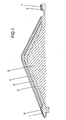
- a blast furnace slag sand is between the sand core 5 layer2 arranged.
- a sticky base 3 is applied to this, while a turf base 4 closes the layering of the dike.
- the blast furnace slag sand intermediate layer also forms a paving bed 8 for embankment stones 11 on the sea side.
- the covering 7 and / or the subsoil 6 of the road may also consist of blast furnace slag sand.
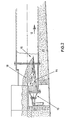
- the device shown in FIG. 2 for producing the blast furnace slag sand used according to the invention has a high-pressure nozzle arrangement 10 which generates a high-pressure water jet 14 which is directed to the right in the direction of the arrow 12 in the drawing and which is designed to be focused.
- the jet pressure of the nozzle arrangement 10 is approximately 8 bar.
- the water jet 14 is designed to focus and is focused onto a focal point region 16. Liquid slag 18 arriving from the blast furnace at a temperature of approximately 1350 ° C. is introduced into this focal point region 16.
- the intense deterrent effect achieved in this way which is further enhanced by the mechanical action of the focusing water jet 14, produces an extraordinarily fine-grained blast furnace slag sand that has an extremely high amorphousness of more than 90%.
- Such a blast furnace slag sand is particularly favorable for the use according to the invention, not only because of the large reactive surface achieved in this way and the resulting high bondability, but also because of the strongly glassy structure, which obviously leads to the formation of fine needles, which are caused by the possible dike pests be spared.
- the blast furnace slag sand then also falls down in the manner shown in the drawing in the form of the slag sand layer 20 which can be removed by means of a conveyor or the like.
Landscapes
- Engineering & Computer Science (AREA)
- General Engineering & Computer Science (AREA)
- Environmental & Geological Engineering (AREA)
- Ocean & Marine Engineering (AREA)
- Mechanical Engineering (AREA)
- Civil Engineering (AREA)
- Structural Engineering (AREA)
- Revetment (AREA)
Description
- Die Erfindung betrifft die Verwendung von Hochofenschlackensand beim Bau von Deichen, welche im wesentlichen aus einem Sandkern und einem darüber angeordneten Kleiboden bestehen.
- Hochofenschlacke, die im wesentlichen aus Kalk, Magnesia, Tonerde und Silikaten besteht, fällt bei der Erzeugung von Roheisen im Hochofen als künstliche Gesteinsschmeize in grossen Mengen an. Wird die noch flüssige, aus dem Hochofen ankommende Schlacke in Wasser rasch abgekühlt, so entsteht der granulierte Hochofenschlakkensand oder Hüttensand, der im Gegensatz zu fester Hochofenschlacke, welche durch langsame Abkühlung des flüssigen Schlackenstromes entsteht und einen hohen Kristallinitätsgrad aufweist, im wesentlichen eine glasige, amorphe Struktur hat, wobei der Amorphizitätsgrad in der Regel bei ca. 90% liegt. Verfahren zur Herstellung dieses Hochofenschlackensandes und seiner Eigenschaften sind beispielsweise in dem Fachbuch "Hochofenschlacke" von Prof. Keil, Düsseldorf 1963, ausführlich beschrieben. Für die Eisen- und Stahlerzeugung der Industrie ist der Hochofenschlackensand ein lästiges Nebenprodukt. Seine Beseitigung und Lagerung ist mit hohen Kosten verbunden, insbesondere deshalb, weil nach einer gewissen Lagerzeit ein Verfestigungseffekt eintritt. Die Verfestigung ist dabei so stark, dass zum Sprengen grosser, aus dem Hochofenschlackensand gebildeter Klumpen pro Tonne ca. 12 kg Dynamit notwendig sind, während beispielsweise Felsgestein lediglich den Einsatz von etwa 1 kg Dynamit pro Tonne erfordert. In der eisen- und stahlerzeugenden Industrie besteht ein erhebliches Interesse, den Hochofenschlackensand positiv für Zwecke verwenden zu können, bei denen der Hochofenschlackensand wegen seiner besonderen Eigenschaften in grosser Menge eingesetzt werden kann, wobei die Transportkosten darüber hinaus relativ gering sein sollen. Unter den positiven Eigenschaften des Hochofenschlackensandes ist insbesondere seine hydraulische Bindefähigkeit zu nennen, die im Laufe der Zeit die vorstehend beschriebene Befestigung bewirkt. Die Durchlässigkeit einer Hochofenschlackensandschicht ist so gross, dass Oberflächenwasser in den Untergrund versickern kann, so dass es bereits bekannt ist, Hochofenschlackensand im Gemisch mit Lehm oder Lehmkies als Deckerde beispielsweise für Park- oder Sportplätze zu verwenden (DE-PC Nr. 476884; DE-A Nr. 2731369).
- Weiterhin ist es bereitsbekannt, Hochofenschlackensand vor allem in der Zementindustrie bei der Herstellung von Hüttenzement einzusetzen. Die Zementindustrie kann jedoch die erheblichen Mengen des ständig anfallenden Hochofenschlackensandes nicht in der für die eisen- und stahlerzeugende Industrie wünschenswerten Weise aufnehmen.
- Aus der DE-A Nr. 2729985 ist bereits eine Verwendung der eingangs beschriebenen Art bekannt, bei der ein Deichkern dadurch gebildet wird, dass eine entsprechend ausgehobene Verschalung mit einem Zementgemisch angefüllt wird, welches unter anderem als Zuschlag Hochofenschlackensand enthält. Der auf diese Weise gebildete wasserabschirmende Kern hat die wünschenswerte Flexibilität, um auch Bodenbewegungen ausgleichen zu können; der Kern selbst wird dann in üblicher Weise mit einer Erdaufschüttung bedeckt, die dann mit dem herkömmlichen Bewuchs versehen wird. Der Hochofenschlackensand wird dabei also lediglich im Zusammenwirken mit Zement verwendet und führt zu einer guten Elastizität der hergestellten beton- ähnlichen Masse, wie dies beispielsweise auch aus dem "Merkblatt über Hochofenschlacke für Tragschichten, Unterbau und Untergrundverbesserung im Strassenbau" der Forschungsgesellschaft für das Strassenwesen, Ausgabe 1972, bekannt ist. Auf diese Weise hergestellte Deiche zeigen wie herkömmliche Deiche das Problem, dass leicht Deichbeschädigungen durch Aufschlag, also durch die Brandung in die Deichböschung geschlagene Löcher, sowie durch Überströmung, beispielsweise infolge Eisstauung, oder durch von Wellenüberschlag verursachte Böschungsrutschungen, Rückbrüche und Kampfstürzeauftreten können, die häufig zur völligen Zerstörung einer Deichstrecke führen. Auch können tierische Schädlinge, wie Erdratten, Mäuse, Maulwürfe, Kaninchen, Füchse und andere sowie bodenbedingte Vorgänge in Form von Setzungs-, Sakkungs- und Schwindungserscheinungen den Bestand des Deiches gefährend.
- Auch aus "Strassenbau-Technik", Nr. 10,1961, S. 549 ff., ist die Verwendung von Hochofenschlacke im Wasserbau bekannt, jedoch handelt es sich dabei um die Verwendung kristalliner Hochofenschlacke, die ggf. vor Einsatz zu Brechsand verarbeitet ist, wobei der Brechsand dann als Zuschlagstoff eingesetzt wird. Die DE-A Nr. 1784264 betrifft die Verwendung von Steinen aus Schmelzschlacke bzw. Hochofenschlacke im Wasserbau, wobei von der Tatsache Gebrauch gemacht wird, dass die Kapillaren der aus der Schlacke gebildeten Steine geschlossen sind, so dass also eine Wasseraufnahme nicht stattfindet. Dabei werden zur Deichbefestigung die Steine in möglichst dichter Packung ausgelegt und in den Fugen mit Beton bzw. Bitumen ausgegossen. Auch derartige Deiche neigen zu den beschriebenen Beschädigungen, wobei aber insbesondere hervorzuheben ist, dass vollständig mit Steinen belegte Deiche nicht nur aus Gründen des Landschaftsschutzes, sondern auch aus Kostengründen nicht durchgehend, sondern lediglich im Bereich von Ortschaften u. dgl. angelegt werden können, während ansonsten Deiche mit Grünbewuchs vorgeschrieben sind. Es ist bereits versucht worden, das Problem des Schädlingsanfalls bei Deichen durch Einbringen von Kunststoffen, wie PVC oder Polyäthylen, zu beheben ("Kunststoffe im Wasserbau", Bauingenieur-Praxis, Heft 125,1971), jedoch haben sich hiermit keine befriedigenden Ergebnisse erzielen lassen. Insbesondere bedeutet das zusätzliche Einbringen von Kunststoffolien usw. einen weiteren Arbeits-und Kostenaufwand, der beim Deichbau in Anbetracht der zu erstellenden Deichstrecken in aller Regel nicht tolerierbar ist.
- Der Erfindung liegt daher die Aufgabe zugrunde, eine Verwendung der eingangs genannten Art zu schaffen, welche die Herstellung von zuverlässig gegen Beschädigungen durch Wasser, durch bodenbedingte Vorgänge, wie Setzungs-, Sakkungs- und Schwindungserscheinungen und insbesondere durch Schädlingsbefall zuverlässig gesicherter Deiche ermöglicht.
- Bei Deichen war es ausserdem bekannt, Hochofenschlacke als Sauberkeitsschicht unter einer Asphaltbetonschicht zu verwenden (1263, "Bitumen", Bd. 38, Nr. 3, 5/6, S. 81 und 82). Fernes war es durch "Civil Engineering-ASCE", vol. 42, Nr. 4, April 1972 bekannt, zum Uferschutz Aufschüttungen aus Hochofenschlacke vorzusehen.
- Erfindungsgemäss wird diese Aufgabe dadurch gelöst, dass zwischen dem Sandkern und dem Kleiboden des Deiches eine durchgehende, ausschliesslich aus Hochofenschlackensand bestehende Zwischenschicht angeordnet wird.
- Eine bevorzugte Ausführungsform der Erfindung sieht vor, dass der Hochofenschlackensand einem Amorphizitätsgrad von mindestens 90% hat.
- Weiterhin wird erfindungsgemäss vorgeschlagen, dass der Hochofenschlackensand die nachstehende Zusammensetzung hat: 0,4 Gew.-% Granalien; 13,4 Gew.-% Wasser; 0,19 Gew.-% unlöslicher Rückstand; 35,20 Gew.-% Si02; 0,70 Gew.-% .Ti02; 11,40 Gew.-% AI203; 0,53 Gew.-% FeO; 0,3 Gew.-% MnO; 41,87 Gew.-% CaO; 5,1 Gew.-% MgO; 3,13 Gew.-% CaS; 0,31 Gew.-% Na20; 0,45 Gew.-% K20; 0,02 Gew.-% S03 und 0,007 Gew.-% P.
- Eine besondere Ausführungsform der Erfindung schlägt weiterhin vor, dass der Hochofenschlackensand durch Einleiten der aus dem Hochofen mit einer Temperatur von mindestens 1300°C ankommenden flüssigen Schlacke in den Brennpunkt eines kalten, fokussierenden Hochdruckwasserstrahles erzeugt wird. Dabei kann insbesondere vorgesehen sein, dass die flüssige Schlacke beim Einleiten in den fokussierenden Wasserstrahl eine Temperatur von ca. 1350° C hat.
- Schliesslich wird durch die Erfindung vorgeschlagen, dass der Wasserstrahl durch eine Düsenanordnung mit einem Druck von ca. 8 bar erzeugt wird.
- Dadurch, dass erfindungsgemäss eine ausschliesslich aus Hochofenschlackensand bestehende Zwischenschicht bei Deichen mit natürlichem Bewuchs zwischen dem Sandkern und dem Kleiboden vorgesehen wird, wobei der Hochofenschlackensand einen ungewöhnlich hohen Amorphizitätsgrad aufweisen muss, werden die vorstehend beschriebenen Deichbeschädigungen zuverlässig vermieden. Auch Witterrungserscheinungen durch Niederschläge, Frost und Trockenheit, welche ansonsten zu Abschwemmungen des Deichbodens, Schäden an der Grasnarbe und zu Schwundrissen im Deichkörper führen können, treten nicht auf. Bewirkt werden all diese positiven Effekte in überraschender Weise dadurch, dass die sich mit der Zeit fortlaufend erhärtende Zwischenschicht aus dem Hochofenschlackensand, die auch nach abgeschlossener Verfestigung ein gewisse Elastizität behält, bei Aufbringung in ausreichender Dicke dem Wasserdruck auch dann widersteht, wenn die Kleidecke, die auf ihr ruht, fortgespült ist, so dass auch eine Hinterspülung des Deiches durch überschlagende Wellen nicht mehr möglich ist. Überraschend ist insbesondere, dass es den genannten Deichschädlingen nicht mehr möglich ist, die Hochofenschlackensandschicht zu durchdringen, wobei dieser überraschende Effekt offenbar darauf beruht, dass der verwendete Hochofenschlackensand wegen seines Amorphizitätsgrades, also seiner hochgradig glasigen Struktur, feinste Nadeln ausbildet, die in das Fell und die Grabwerkzeuge der Schädlingen eindringen, so dass diese von ihre Wühltätigkeit bei Erreichen der Hochofenschlackensandzwischenschicht von der bewachsenen Oberfläche des Deiches her alsbald ablassen. Das bekannte Phänomen, dass Deiche durch von tierischen Schädlingen gegrabene Bauten geschwächst werden, lässt sich somit zuverlässig vermeiden.
- Im übrigen lässt sich Hochofenschlackensand, wie er erfindungsgemäss verwendet wird, auch als Pflasterbett zur Aufnahme der Pflastersteine im Bereich der Steinböschung von Deichen einsetzen. Auch für die zum Deichbau notwendigen Bauwege lässt sich der Hochofenschlackensand natürlich in bekannter Weise verwenden, da sich eine hieraus hergestellte Tragschicht bereits vor der Verdichtung mit einer Vibrationsglattradwalze od. dgl. von schweren Fahrzeugen befahren lässt, ohne dass wesentliche Verformungen auftreten. Für diese an sich bekannten Zwecke kann der Hochofenschlackensand natürlich auch mit Zement gebunden werden, während ein erfindungswesentliches Merkmal gerade darin besteht, dass für die Zwischenschicht zwischen dem Sandkern und dem Kleiboden ausschliesslich Hochofenschlackensand eingesetzt wird.
- Von Vorteil ist die Verwendung von Hochofenschlackensand anstelle von Zement beim Deichbau auch deshalb, weil der Hochofenschlackensand aus den bereits dargelegten Gründen ausgesprochen kostengünstig ist. Dies trifft vor allem dann zu, wenn die Transportkosten sehr gering sind, wie dies häufig der Fall ist, weil Hochöfen in der Regel an Wasserstrassen gelegen sind und der Transport des Hochofenschlackensandes vom Hochofen zur Deichbaustelle aus diesem Grunde per Schiff vorgenommen werden kann.
- Weitere Merkmale und Vorteile der Erfindung ergeben sich aus der nachfolgenden Beschreibung, in der ein Ausführungsbeispiel anhand der schematischen Zeichnung im einzelnen erläutert ist. Dabei zeigt:
- Fig. 1 einen erfindungsgemäss hergestellten Deich im Querschnitt, und
- Fig. 2 eine Vorrichtung zur Herstellung des erfindungsgemäss verwendeten Hochofenschlakkensandes im vertikalen Schnitt.
- Wie Fig. 1 erkennen lässt, ist oberhalb des Sandkernes 5 eine Hochofenschlackensandzwischenschicht2 angeordnet. Auf diese ist ein Kleiboden 3 aufgebracht, während ein Rasensoden 4 die Schichtung des Deiches abschliesst. Seeseitig bildet die Hochofenschlackensandzwischenschicht zugleich ein Pflasterbett 8 für Böschungssteine 11.
- Landseitig bestehen der Belag 7 und/oder der Untergrund 6 der Strasse ggf. ebenfalls auf Hochofenschlackensand.
- Die in Fig. 2 gezeigte Vorrichtung zur Herstellung des erfindungsgemäss verwendeten Hochofenschlackensandes weist eine Hochdruckdüsenanordnung 10 auf, die einen in der Zeichnung in Richtung des Pfeiles 12 nach rechts gerichteten Hochdruckwasserstrahl 14 erzeugt, der fokussierend ausgebildet ist. Der Strahldruck der Düsenanordnung 10 beträgt ca. 8 bar. Der Wasserstrahl 14 ist fokussierend ausgebildet und wird auf einen Brennpunktbereich 16 hin gebündelt. In diesen Brennpunktbereich 16 wird aus dem Hochofen mit einer Temperatur von ca. 1350° C ankommende flüssige Schlacke 18 eingeleitet. Durch den auf diese Weise erzielten intensiven Abschreckungseffekt, der durch die mechanische Wirkung des fokussierenden Wasserstrahles 14 noch verstärkt wird, wird ein ausserordentlich feinkörniger Hochofenschlackensand erzeugt, der eine extrem hohe Amorphizität von mehr als 90% aufweist. Ein derartiger Hochofenschlackensand ist für die erfindungsgemässe Verwendung besonders günstig, nicht nur wegen der auf diese Weise erzielten grossen reaktiven Oberfläche und der dadurch hervorgerufenen hohen Bindefähigkeit, sondern auch wegen der stark glasigen Struktur, die offenbar zur Ausbildung feiner Nädelchen führt, die durch die möglichen Deichschädlinge gescheut werden.
- Der Hochofenschlackensand fällt dann im übrigen nach unten in der aus der Zeichnung ersichtlichen Weise in Form der mittels eines Förderers od. dgl. abtransportierbaren Schlackensandschicht 20 aus.
Bezugszeichenliste →
Claims (6)

Priority Applications (1)
| Application Number | Priority Date | Filing Date | Title |
|---|---|---|---|
| DK134782A DK154094C (da) | 1981-03-24 | 1982-03-24 | Anvendelse af hoejovnsslaggesand ved dige- eller daemningsbygning |
Applications Claiming Priority (2)
| Application Number | Priority Date | Filing Date | Title |
|---|---|---|---|
| DE3111471 | 1981-03-24 | ||
| DE3111471 | 1981-03-24 |
Publications (2)
| Publication Number | Publication Date |
|---|---|
| EP0061135A1 EP0061135A1 (de) | 1982-09-29 |
| EP0061135B1 true EP0061135B1 (de) | 1985-01-16 |
Family
ID=6128115
Family Applications (1)
| Application Number | Title | Priority Date | Filing Date |
|---|---|---|---|
| EP82102148A Expired EP0061135B1 (de) | 1981-03-24 | 1982-03-17 | Verwendung von Hochofen-Schlackensand beim Deichbau |
Country Status (2)
| Country | Link |
|---|---|
| EP (1) | EP0061135B1 (de) |
| DE (1) | DE3261896D1 (de) |
Family Cites Families (5)
| Publication number | Priority date | Publication date | Assignee | Title |
|---|---|---|---|---|
| NL22480C (de) * | 1927-01-06 | 1928-11-15 | ||
| DE1784264A1 (de) * | 1968-07-24 | 1971-10-07 | Paul Becker | Verwendung von Steinen aus Schmelzschlacke im Wasserbau und Strassenbau |
| LU77160A1 (de) * | 1977-04-19 | 1979-01-18 | ||
| DE2729985A1 (de) * | 1977-07-02 | 1979-01-18 | Nichireki Chem Ind Co | Verfahren zum bau von fugenlosen abdichtungswaenden und kernen von geschuetteten daemmen |
| DE2731369A1 (de) * | 1977-07-12 | 1979-01-18 | Peter W Thielemann Fa | Deckerdegemisch |
-
1982
- 1982-03-17 EP EP82102148A patent/EP0061135B1/de not_active Expired
- 1982-03-17 DE DE8282102148T patent/DE3261896D1/de not_active Expired
Also Published As
| Publication number | Publication date |
|---|---|
| DE3261896D1 (en) | 1985-02-28 |
| EP0061135A1 (de) | 1982-09-29 |
Similar Documents
| Publication | Publication Date | Title |
|---|---|---|
| EP1358299B2 (de) | Verfahren zur herstellung von böden oder trennschichten | |
| DE2856764A1 (de) | Beton- oder moertelmischung bzw. beton oder moertel und verfahren zu ihrer herstellung | |
| DE2306428B2 (de) | Gleisoberbau und verfahren zu dessen herstellung | |
| DE3439224A1 (de) | Vegetationsschicht aus mineralischem gemenge | |
| US4826350A (en) | Method for constructing water-permeable sports surface and the like | |
| EP0061135B1 (de) | Verwendung von Hochofen-Schlackensand beim Deichbau | |
| LU502430B1 (de) | Ein Verfahren zum Bau einer Brücke an einem rutschgefähderten Böschungen und eine Brücke | |
| DE2522851A1 (de) | Hydraulisch abbindender baustoff fuer den strassenbau | |
| JP3080288B2 (ja) | 舗装材とその製造方法 | |
| DE2501312A1 (de) | Verfahren zur verbesserung der tragfaehigkeit und frostbestaendigkeit einer kohlen- und muellasche enthaltenden, fuer verkehrswege und sonstige schuettungen geeigneten masse | |
| EP1655410A1 (de) | Verfahren zur Herstellung einer Tragschicht | |
| DE828555C (de) | Verfahren zur Herstellung von Zementfahrbahndecken ohne Fugen | |
| EP0407546B1 (de) | Verfahren zur verfestigung und/oder abdichtung von altdeponien von abfallstoffen | |
| DE2634189A1 (de) | Verfahren und bindemittel zur verfestigung von boeden | |
| DE20214224U1 (de) | Drainagepflaster | |
| DE1962850B2 (de) | Wasserdurchlaessige bituminoese gemische auf der grundlage eines bitumenmoertels und ihre verwendung in der wasserbautechnik | |
| AT409008B (de) | Mineralisches haufwerk, verfahren zu seiner herstellung, künettenverfüllmaterial sowie künettenfüllungen | |
| DE2032574C3 (de) | Abdichtung von Steindämmen, Erdschüttungen oder natürlichen Böschungen | |
| US155990A (en) | Improvement in methods of preparing slag for use in the manufacture of artificial | |
| AT204492B (de) | Verfahren zur Abdichtung und Befestigung von Böden | |
| DE1035064B (de) | Dichtung fuer Sperren von Wasserspeichern aus zwei eine flexible Sickerschicht einschliessenden Dichtungslagen | |
| DE2547717A1 (de) | Geschuetteter staudamm und verfahren zu dessen herstellung | |
| Hansen et al. | Construction of stair-stepped soil-cement bank protection | |
| DE102006003085A1 (de) | Geotextiles Flächengebilde für die Verwendung im Erd-, Straßen- und/oder Tiefbau, aufweisend Bambusfasern | |
| DE2729985A1 (de) | Verfahren zum bau von fugenlosen abdichtungswaenden und kernen von geschuetteten daemmen |
Legal Events
| Date | Code | Title | Description |
|---|---|---|---|
| PUAI | Public reference made under article 153(3) epc to a published international application that has entered the european phase |
Free format text: ORIGINAL CODE: 0009012 |
|
| AK | Designated contracting states |
Designated state(s): BE DE FR GB IT NL |
|
| 17P | Request for examination filed |
Effective date: 19830324 |
|
| ITF | It: translation for a ep patent filed | ||
| GRAA | (expected) grant |
Free format text: ORIGINAL CODE: 0009210 |
|
| AK | Designated contracting states |
Designated state(s): BE DE FR GB IT NL |
|
| REF | Corresponds to: |
Ref document number: 3261896 Country of ref document: DE Date of ref document: 19850228 |
|
| ET | Fr: translation filed | ||
| PLBE | No opposition filed within time limit |
Free format text: ORIGINAL CODE: 0009261 |
|
| STAA | Information on the status of an ep patent application or granted ep patent |
Free format text: STATUS: NO OPPOSITION FILED WITHIN TIME LIMIT |
|
| 26N | No opposition filed | ||
| ITTA | It: last paid annual fee | ||
| PGFP | Annual fee paid to national office [announced via postgrant information from national office to epo] |
Ref country code: GB Payment date: 19920316 Year of fee payment: 11 |
|
| PGFP | Annual fee paid to national office [announced via postgrant information from national office to epo] |
Ref country code: FR Payment date: 19920323 Year of fee payment: 11 |
|
| PGFP | Annual fee paid to national office [announced via postgrant information from national office to epo] |
Ref country code: NL Payment date: 19920331 Year of fee payment: 11 |
|
| PGFP | Annual fee paid to national office [announced via postgrant information from national office to epo] |
Ref country code: BE Payment date: 19920512 Year of fee payment: 11 |
|
| PGFP | Annual fee paid to national office [announced via postgrant information from national office to epo] |
Ref country code: DE Payment date: 19920615 Year of fee payment: 11 |
|
| PG25 | Lapsed in a contracting state [announced via postgrant information from national office to epo] |
Ref country code: GB Effective date: 19930317 |
|
| PG25 | Lapsed in a contracting state [announced via postgrant information from national office to epo] |
Ref country code: BE Effective date: 19930331 |
|
| BERE | Be: lapsed |
Owner name: GUNTHER MARTENS K.G. Effective date: 19930331 |
|
| PG25 | Lapsed in a contracting state [announced via postgrant information from national office to epo] |
Ref country code: NL Effective date: 19931001 |
|
| NLV4 | Nl: lapsed or anulled due to non-payment of the annual fee | ||
| GBPC | Gb: european patent ceased through non-payment of renewal fee |
Effective date: 19930317 |
|
| PG25 | Lapsed in a contracting state [announced via postgrant information from national office to epo] |
Ref country code: FR Effective date: 19931130 |
|
| PG25 | Lapsed in a contracting state [announced via postgrant information from national office to epo] |
Ref country code: DE Effective date: 19931201 |
|
| REG | Reference to a national code |
Ref country code: FR Ref legal event code: ST |