EP0061064A2 - Appareil de déplacement de fluide avec piston à mouvement orbital et mécanime empêchant la rotation - Google Patents
Appareil de déplacement de fluide avec piston à mouvement orbital et mécanime empêchant la rotation Download PDFInfo
- Publication number
- EP0061064A2 EP0061064A2 EP82101875A EP82101875A EP0061064A2 EP 0061064 A2 EP0061064 A2 EP 0061064A2 EP 82101875 A EP82101875 A EP 82101875A EP 82101875 A EP82101875 A EP 82101875A EP 0061064 A2 EP0061064 A2 EP 0061064A2
- Authority
- EP
- European Patent Office
- Prior art keywords
- orbital
- fixed
- race
- ring
- pockets
- Prior art date
- Legal status (The legal status is an assumption and is not a legal conclusion. Google has not performed a legal analysis and makes no representation as to the accuracy of the status listed.)
- Granted
Links
- 239000012530 fluid Substances 0.000 title claims abstract description 52
- 238000006073 displacement reaction Methods 0.000 title claims abstract description 18
- 230000007246 mechanism Effects 0.000 title claims description 10
- 230000008859 change Effects 0.000 claims description 2
- 230000000149 penetrating effect Effects 0.000 claims 2
- 238000010276 construction Methods 0.000 description 5
- 238000007373 indentation Methods 0.000 description 4
- 230000004048 modification Effects 0.000 description 4
- 238000012986 modification Methods 0.000 description 4
- 230000002093 peripheral effect Effects 0.000 description 3
- 238000006243 chemical reaction Methods 0.000 description 2
- 230000006835 compression Effects 0.000 description 2
- 238000007906 compression Methods 0.000 description 2
- 239000003507 refrigerant Substances 0.000 description 2
- 238000007789 sealing Methods 0.000 description 2
- 230000007423 decrease Effects 0.000 description 1
- 230000001419 dependent effect Effects 0.000 description 1
- 230000000694 effects Effects 0.000 description 1
- ZZUFCTLCJUWOSV-UHFFFAOYSA-N furosemide Chemical compound C1=C(Cl)C(S(=O)(=O)N)=CC(C(O)=O)=C1NCC1=CC=CO1 ZZUFCTLCJUWOSV-UHFFFAOYSA-N 0.000 description 1
- 230000006872 improvement Effects 0.000 description 1
- 230000003993 interaction Effects 0.000 description 1
- 238000004519 manufacturing process Methods 0.000 description 1
- 239000000463 material Substances 0.000 description 1
- 230000013011 mating Effects 0.000 description 1
- 230000035515 penetration Effects 0.000 description 1
- 230000002265 prevention Effects 0.000 description 1
- 230000009467 reduction Effects 0.000 description 1
Images

Classifications
-
- F—MECHANICAL ENGINEERING; LIGHTING; HEATING; WEAPONS; BLASTING
- F01—MACHINES OR ENGINES IN GENERAL; ENGINE PLANTS IN GENERAL; STEAM ENGINES
- F01C—ROTARY-PISTON OR OSCILLATING-PISTON MACHINES OR ENGINES
- F01C17/00—Arrangements for drive of co-operating members, e.g. for rotary piston and casing
- F01C17/06—Arrangements for drive of co-operating members, e.g. for rotary piston and casing using cranks, universal joints or similar elements
- F01C17/063—Arrangements for drive of co-operating members, e.g. for rotary piston and casing using cranks, universal joints or similar elements with only rolling movement
-
- F—MECHANICAL ENGINEERING; LIGHTING; HEATING; WEAPONS; BLASTING
- F01—MACHINES OR ENGINES IN GENERAL; ENGINE PLANTS IN GENERAL; STEAM ENGINES
- F01C—ROTARY-PISTON OR OSCILLATING-PISTON MACHINES OR ENGINES
- F01C1/00—Rotary-piston machines or engines
- F01C1/02—Rotary-piston machines or engines of arcuate-engagement type, i.e. with circular translatory movement of co-operating members, each member having the same number of teeth or tooth-equivalents
- F01C1/0207—Rotary-piston machines or engines of arcuate-engagement type, i.e. with circular translatory movement of co-operating members, each member having the same number of teeth or tooth-equivalents both members having co-operating elements in spiral form
- F01C1/0215—Rotary-piston machines or engines of arcuate-engagement type, i.e. with circular translatory movement of co-operating members, each member having the same number of teeth or tooth-equivalents both members having co-operating elements in spiral form where only one member is moving
-
- F—MECHANICAL ENGINEERING; LIGHTING; HEATING; WEAPONS; BLASTING
- F04—POSITIVE - DISPLACEMENT MACHINES FOR LIQUIDS; PUMPS FOR LIQUIDS OR ELASTIC FLUIDS
- F04C—ROTARY-PISTON, OR OSCILLATING-PISTON, POSITIVE-DISPLACEMENT MACHINES FOR LIQUIDS; ROTARY-PISTON, OR OSCILLATING-PISTON, POSITIVE-DISPLACEMENT PUMPS
- F04C29/00—Component parts, details or accessories of pumps or pumping installations, not provided for in groups F04C18/00 - F04C28/00
- F04C29/0021—Systems for the equilibration of forces acting on the pump
-
- F—MECHANICAL ENGINEERING; LIGHTING; HEATING; WEAPONS; BLASTING
- F16—ENGINEERING ELEMENTS AND UNITS; GENERAL MEASURES FOR PRODUCING AND MAINTAINING EFFECTIVE FUNCTIONING OF MACHINES OR INSTALLATIONS; THERMAL INSULATION IN GENERAL
- F16C—SHAFTS; FLEXIBLE SHAFTS; ELEMENTS OR CRANKSHAFT MECHANISMS; ROTARY BODIES OTHER THAN GEARING ELEMENTS; BEARINGS
- F16C2360/00—Engines or pumps
- F16C2360/42—Pumps with cylinders or pistons
Definitions
- This invention relates to a rotary fluid displacement apparatus,and more particularly,to an improvement in a rotation preventing/thrust bearing device for an orbiting piston type fluid displacement apparatus.
- piston is used generically to describe a movable member of any suitable configuration within fluid apparatus.
- one of scroll members is fixed to a housing and the other scroll member,which is the orbiting scroll member,is eccentrically supported on a crank pin of a rotating shaft to cause orbital motion.
- the scroll type apparatus also includes a rotation preventing device which prevents rotation of the orbiting scroll member to thereby maintain the scroll members in a predetermined angular relationship during operation of the apparatus.
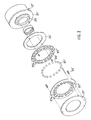
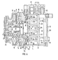
- Fig.1 is a vertical sectional view of a part of compressor and Fig. 2 is an exploded perspective view of rotation preventing/thrust bearing device
- the rotation preventing/thrust bearing device 37' surrounds boss 273' of orbiting scroll member 27' and includes an orbital portion, a fixed portion and bearings,such as a plurality of balls.
- the fixed portions includes (1) an annular fixed race 371' having one end surface fitted against the axial end surface of annular projection 112' of front end plate 11',and (2) a fixed ring 372' fitted against the other axial end surface of fixed race 371' to extend outwardly therefrom and cover the other end surface of fixed race 371'.
- the orbital portion also includes (1) an annular orbital race 374',which has one end surface fitted against an axial end surface of circular plate 271' and (2) an orbital ring 375' fitted against the other axial end surface of orbital race 374' to extend outwardly therefrom and cover the other axial end surface of orbital race 374.
- a small clearance is maintained between the end surface of fixed ring 372' and the end surface of orbital ring 375.
- Orbital race 374' and ring 375' are attached to the end surface of circular plate 271' by pin 376'.
- Fixed ring 372' and orbital ring 375' each have a plurality of holes or pockets 372a' and 375a' in the axial direction,the number of holes or pockets in each ring 372',375' being equal.
- Bearing elements such as balls or spheres 377',are placed between facing generally aligned pairs of pockets 372a',375a' of fixed and orbital rings 372 ⁇ 375',with the rings 372',375' facing one another at a predetermined clearance.
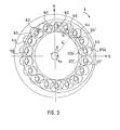
- FIG.3 the center of orbital ring 37 5' is placed at the right side and the direction of rotation of the drive shaft is clockwise as indicated by arrow A.
- the center of orbital ring 375' orbits about a circule of radius R o (together with orbiting scroll 27').
- a rotating force i.e., moment, which is caused by the offset of the acting point of the reaction force of compression and the acting point of drive force,acts on orbiting scroll 27'.
- This reaction force tends to rotate orbiting scroll 27' in a clockwise direction about the center of orbital ring 375'.
- the rotation preventing/thrust bearing device is made up of a pair of races and a pair of rings,with each race and ring formed separately. Therefore, the parts of the rotation preventing/ thrust bearing device are easy to construct and the most suitable material for each part can be selected.
- each ring is attached by a pin, respectively.
- the rotation preventing force of rings is thus transmitted to- the attachment pins. Since the location at which the rotation preventing force of the rings act on the respective attachment pins is spaced from the location at which the pins are attached to the orbiting scroll or housing, a moment is generated which acts on the pins. If both an associated ring and race are attached by a respective pin,this spacing increases,with the result that the stress on the pin also is increased. Also, stress is placed on the attachment pins by the impact load which occurs when the compressor unit is driven at high speed. Because of these factors, it is desirable to reduce the stress in the attachment pins.
- An orbiting piston type fluid diplacement apparatus includes a housing.
- a fixed cylinder attched to or integral with the housing.
- An orbiting piston has an end plate from which an annular piston extends.
- the cylinder and annular piston interfitting at a radial offset ___ to make a line contact to separated an outlet fluid from the inlet fluid.
- a driving mechanism including a drive shaft,which is rotatably supported by the housing and connected to the orbiting piston to effect the orbital motion of the orbiting piston.
- a rotation preventing/thrust bearing device is connected to the orbiting piston for preventing the rotation of the orbiting piston during orbital motion so that the line contact moves toward the discharge side during orbital motion of the orbiting piston.
- the rotation preventing/thrust bearing device comprises an orbital portion, a fixed portion and a plurality of bearings such as balls or spheres.
- the orbital portion includes an annular race and ring both of which are formed separately.
- the race is placed within an annular groove formed on the end surface of the end plate opposite to the side from which the orbiting piston extends.
- the ring is attached to the end surface. of end plate to cover the race and has a plurality of pockets formed in an axial direction toward the race.
- the fixed portion includes a second annular race and a second ring both of which are formed separatly.
- the second race is placed within an annular groove formed on an inner surface of the housing.
- the second ring is attached to the inner surface of the housing to cover the second race and has a plurality of second pockets formed in an axial direction toward the second race.
- a clearance is maintaimed between the ring of the robital portion and the ring of the fixed portion.
- the bearings are placed between generally aligned first and second pockets of the rings. The rotation of the orbiting piston is thus prevented by the bearings which are placed in the pockets of both rings and the thrust load from the orbiting piston is supported by the race of fixed portion through the bearings.
- the compressor unit 1 includes a compressor housing 10 having a front end plate 11 and a cup shaped casing 12 which is attached to an end surface of front end plate 11.
- An opening 111 is formed in the center of front end plate 11 for the penetration or passage of a drive shaft 13.
- An annular projection 112 is formed in a rear end surface of front end plate 11.
- Annular projection 112 faces cup shaped casing 12 ___ and is concentric with opening 111.
- An outer peripheral surface of annular projection 112 extends into an inner wall of the opening of cup shaped casing 12.
- Cup shaped casing 12 is fixed on the rear end surface of front end plate 11 by a fastening device,for example,bolts and nuts.
- the opening portion of cup shaped casing 12 is thus covered by front end plate 11.
- An 0-ring 14 is placed between the outer peripheral surface of annular projection 112 and the inner wall of the opening of cup shaped casing 12, to seal the mating surfaces of front end plate 11 and cup shaped casing 12.
- Front end plate 11 has an annular sleeve 15 projecting from the front end surface thereof which surrounds drive shaft 13 and defines a shaft seal cavity.
- sleeve 15 is separate from front end plate 11. Therefore, sleeve 15-is fixed to the front end surface of front end plate 11 by screws (not shown).
- An 0-ring 16 is placed between the end surface of front end plate 11 and an end surface of sleeve 15 to seal fitting surface of front end plate 11 and sleeve 15.
- sleeve 15 may be integral with front end plate 11.
- Drive shaft 13 is rotatably supported by sleeve 15 through a bearing device 17 located within the front end of sleeve 15.
- Drive shaft 13 has a disk 18 at its inner which is rotatably supported by front end plate 11 through a bearing device 19 located within opening 111 of front end plate 11.
- a shaft seal assembly 20 is coupled to drive shaft 13 within the shaft seal cavity of sleeve 15.
- a pulley 21 is rotatably supported by a bearing assembly 22 which Is carried on the outer surface of sleeve 15.
- An electromagnetic coil 23 is fixed about the outer surface of sleeve 15 by a support plate 24 and is received in an annular cavity of pulley 21.
- An armature plate 25 is elastically supported on the outer end of drive shaft 13 which extends from sleeve 15.
- a magnetic clutch thus includes pulley 21,magnetic coil 23 and armature plate 25. In operation, drive shaft 13 is driven by an external drive power source, for example, a vehicle engine, through a rotation force transmitting device such as the above described magnetic clutch.
- a fixed scroll 26,an orbiting scroll 27,an orbiting scroll 27, a driving- mechanism for orbiting scroll 27 and a rotation preventing/thrust bearing device for orbiting scroll 27 are located within an inner chamber of cup shaped casing 12.
- the inner chamber is formed between the inner wall of cup shaped casing 12 and front end plate 11.
- Fixed scroll 26 includes a circular end plate 261, a wrap or spiral element 262 affixed to or extending from one side surface of circular end plate 261, and a plurality of internally threaded bosses 263 axially projecting from the other end surface of circular plate 261.
- An end surface of each boss 263 is seated on the inner surface of an end plate 121 of cup shaped casing 12 and is fixed to end plate 121 by bolts 28.
- Fixed scroll 26 is thus fixed within cup shaped casing 12.
- Circular end plate 261 of fixed scroll 26 divides the inner chamber of cup shaped casing 12 into a discharge chamber 30 and a suction chamber 29 with a seal ring 31 placed between the outer peripheral surface of circular plate 261 and the inner wall of cup shaped casing 12.
- a hole or discharge port 264 is formed through circular plate 261 at a position near the center of spiral element 262; discharge port 264 is connected between the fluid pockets of the spiral.element 262 and discharge chamber 30.
- Orbiting scroll 27 also includes a circular end plate 271 and a wrap or spiral element 272 affixed to or extending from one side surface of circular end plate 271. Spiral element 272 and spiral element 262 of fixed scroll 26 interfit at angular offset of 180° and a pred termined radial offset. At least a pair of fluid pockets are thereby defined between both spiral element 262 and 272. Orbiting scroll 27 which is connected to the drive mechanism and to the rotation preventing/thrust bearing device, is driven in an orbital motion at a circular radius Ro by rotation of drive shaft 13 to thereby compress fluid passing through the compressor unit.
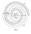
- Radius Ro of orbital motion given by the following formula
- the pitch (P) of the spiral elements can be defined by 2 rg, where rg is the involute generating circle radius-
- the radius of orbital motion Ro is also illustrated in Fig.8 as the locus of an arbitrary point Q on wrap 272 of orbiting scroll 27.
- the spiral element 272 is radially offset from spiral element 262 of fixed scroll 26 by the distance Ro.
- orbiting scroll 27 undergoes orbital motion of a radius Ro upon rotation of drive shaft 13.
- the line contacts between both spiral element 262 and 272 moves toward the center of the spiral elements along the surfaces of the spiral elements.
- Fluid pockets which are defined between spiral elements 262 and 272,also move to the center with a consequent reduction in volume and compression of the fluid in the fluid pockets.
- the fluid or refrigerant gas which is introduced into suction chamber 29 from an external fluid circuit through an inlet port 31, is taken into fluid pockets formed between spiral elements 262 and 272 from the outer end portions of the spiral elements.
- fluid i:. the fluid pockets is compressed and the compressed fluid is discharged into discharge chamber 30 from the central fluid pocket of the spiral element through hole 264. The fluid then is discharged to the external fluid circuit through an outlet port 32.
- a discoid or short axial bushing 34 fits into boss 273 and is rotatably supported therein by a bearing such as a needle bearing 35.
- Bushing 34 has a balance weight 341,which has the shape of a portion of a disk or ring and extends radially from bushing 34 along a front surface thereof.
- An eccentric hole 342 is formed in bushing 34 at a position radially offset from center of bushing 34.
- Drive pin 33 fits into the eccentrically disposed hole 342 together with a bearing 36.
- Bushing 34 is therefore driven in an orbital path by the revolution of drive pin 33 and rotates within needle bearing 35.
- orbiting scroll 27 is prevented by a rotation preventing/thrust bearing 37 which is located between the inner surface of housing 10 and circular plate 271 of orbiting scroll 27.
- a rotation preventing/thrust bearing 37 which is located between the inner surface of housing 10 and circular plate 271 of orbiting scroll 27.
- Rotation preventing/thrust bearing device 37 surrounds boss 273 of orbiting scroll 27 and includes an orbital portion, a fixed portion and bearings,such as a plurality of balls.
- the fixed portion includes (1) an annular fixed race 371 which is placed within a groove 113 formed on the axial end surface of annular projection 112 of front end plate 11, and (2) a fixed ring 372 fitted against the axial end surface of annular projection 112 of front end plate 11 to cover the end surface of fixed race 371.
- Fixed ring 372 is attached to the axial end surface of annular projection 112 by pins 373 and fixed race 371 is fixed in groove 113 by fitting,i.e.,a friction fit.
- the orbital portion also includes (1) an annular orbital race 374, whicht is placed within a groove 274 formed on the axial end surface of circular plate 271 of orbiting scroll 27, and (2) an orbital ring 375 fitted against the axial end surface of circular end plate 271 of orbiting scroll 27 to cover the axial end surface of orbital race 374.
- a small clearance is maintained between the end surface of fixed ring 372 and the end surface of orbital ring 375.
- Orbital ring 375 is attached to the end surface of circular end plate 271 by pins 376 and orbital race is fixed in groove 274 by fitting.
- Fixed ring 372 and orbital ring 375 each have a plurality of holes or pockets 372a and 375a in the axial direction, the number of holes or pockets in each rings 372,375 being equal.
- the holes or pock-es 372a on fixed ring 372 correspond to or are a mirror image of the holes or pockets 375a on orbital ring 375,i.e., each pair of pockets facing each other have the same size and pitch, and the radial distance of the pockets from the center of their respective rings 372 and 375 is the same, i.e., the centers of the pockets are located at the same distance from the center of the rings 372 and 375.
- the distance between the supporting point of the pins and the acting point of the rotation preventing force is reduced since the pin only has to penetrate the ring, rather than both the ring and the race.
- the stress on the supporting point of the pins is thereby reduced and likelihood of breakage of the attachment pins is reduced.
- Groove 274 does not extend radially inward as far as the radially innermost edge of ring 375, so that the width, i.e, the distance between the inner and outer diameters of race 374 can be kept small.
- groove 113 does not extend radially outward as far as the radially outward most edge of ring 372, so that the width of race 371 can be kept small.
- this embodiment of rotation preventing/thrust bearing devices both reduces stress on the attachment pins and reduces the weight of the races.
- rotation prevention is more effective if the distance between the contact point of the ball and the edge of the pockets and the end surface of the race is larger, i.e., the contact point of the ball and the edge of pockets is placed close to a center line passing through the center of the ball and parallel to the end surfaces of the rings.
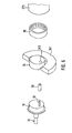
- FIG. 6 still another embodiment of this invention is shown, illustrating a modification of the construction for fixing the rings to improve rotation preventing.
- the thickness of rings 372 and 375 is reduced so that a thinner portion of the rings bears the attachment force of pins 373 and 376.
- the rings 372 and 375 are attached to the outermost surfaces of annular projection 112 and circular plate 271 by fasteners 373 and 376, respectively. These outermost surfaces are located as close to one another as possible in order to place the thinner rings 372 and 375 as close as possible to the center line of balls 377 while still maintaining a clearance between the rings.
- a first groove 113 and a second groove 115 are formed in the end surface of annular projection 112.
- First groove 113 is radially innermost and deepest.
- Fixed race 371 is carried in groove 113 and has an axial end surface flush with the axial end surface of second groove 115.
- the depth of second groove 115 defines a clearance (G) between fixed race 371 and fixed ring 372.
- a first groove 374 and a second groove 275 are formed in the end surface of circular plate 27L
- First groove 274 is radially outermost and deepest.
- Orbital race 374 is carried in groove 274 and has an axial end surface flush with the axial end surface of second groove 275.
- the depth of second groove 275 defines a clearance (G) between orbital race 374 and orbital ring 375.
- the rotation preventing function is optimized by placing rings 3 7 2 and 37.5 as close as possible to the center line of balls 377, while at the same time reducing the weight of device 37 by making the rings 372 and 375 thin and keeping the width of races 371 and 374 small.
- Fig. 7 illustrates a modification of. the ring construction shown in Fig. 6. Only a single groove 113 is formed in annular projection 112, and only a single groove 274 is formed in the end surface of circular plate 271. Fixed race 371 is supported in groove 113 and orbital race 374 is supported in groove 274. Fixed ring 372 has a thin radially inner portion and a thick radially outer portion. Pockets 372a are formed in the thin portion and the thick portion is placed in contact with the end surface of annular projection 112. Fasteners 373 penetrate the thick portion of fixed ring 372 and attached it to projection 112. A clearance (G) is defined between the end surface fixed race 371, which is flush with the end surface of projection 112, and the axial surface of the thin portion of fixed ring 372 which faces race 371.
- G clearance
- orbital ring 375 has a thin radially outer portion and a thick radially inner portion. Pockets 375a are formed in the thin portion and the thick portion is placed in contact with the end surface of circular plate 271. Fasteners 376 penetrate the thick portion of ring 375 and attach it to plate 271. A clearance (G) is defined between the end surface of orbital race 374, which is flush with the end surface of plate 271, and the axial surface of the thin portion of orbital ring 375 which faces race 374.
- the rotation preventing/thrust bearing device 37-of Fig. 7 also optimizes the rotation preventing function by placing rings 372 and 375 as close as possible to the center line of balls 377, while at the same time reducing the weight of the device by making a portion of rings 372 and 375 thin and keeping the width of races 371 and 374 small.
Landscapes
- Engineering & Computer Science (AREA)
- Mechanical Engineering (AREA)
- General Engineering & Computer Science (AREA)
- Rotary Pumps (AREA)
- Rolling Contact Bearings (AREA)
Applications Claiming Priority (2)
| Application Number | Priority Date | Filing Date | Title |
|---|---|---|---|
| JP33644/81 | 1981-03-09 | ||
| JP56033644A JPS57148087A (en) | 1981-03-09 | 1981-03-09 | Scroll type compressor |
Publications (3)
| Publication Number | Publication Date |
|---|---|
| EP0061064A2 true EP0061064A2 (fr) | 1982-09-29 |
| EP0061064A3 EP0061064A3 (en) | 1983-05-04 |
| EP0061064B1 EP0061064B1 (fr) | 1985-06-26 |
Family
ID=12392150
Family Applications (1)
| Application Number | Title | Priority Date | Filing Date |
|---|---|---|---|
| EP82101875A Expired EP0061064B1 (fr) | 1981-03-09 | 1982-03-09 | Appareil de déplacement de fluide avec piston à mouvement orbital et mécanime empêchant la rotation |
Country Status (7)
| Country | Link |
|---|---|
| US (1) | US4492543A (fr) |
| EP (1) | EP0061064B1 (fr) |
| JP (1) | JPS57148087A (fr) |
| AU (1) | AU554240B2 (fr) |
| DE (1) | DE3264372D1 (fr) |
| MY (1) | MY8700529A (fr) |
| SG (1) | SG26587G (fr) |
Cited By (2)
| Publication number | Priority date | Publication date | Assignee | Title |
|---|---|---|---|---|
| US4505651A (en) * | 1982-08-07 | 1985-03-19 | Sanden Corporation | Scroll type compressor with displacement adjusting mechanism |
| DE3525616A1 (de) * | 1985-04-19 | 1986-10-30 | Pierburg Gmbh & Co Kg, 4040 Neuss | Rotationskolbenmaschine |
Families Citing this family (19)
| Publication number | Priority date | Publication date | Assignee | Title |
|---|---|---|---|---|
| JPS59142488U (ja) * | 1983-03-15 | 1984-09-22 | サンデン株式会社 | 旋回ピストン式流体装置の回転阻止機構 |
| JPS59142486U (ja) * | 1983-03-15 | 1984-09-22 | サンデン株式会社 | 旋回ピストン式流体装置の回転阻止機構 |
| JPS59142483U (ja) * | 1983-03-15 | 1984-09-22 | サンデン株式会社 | スクロ−ル型圧縮機の回転阻止機構 |
| US4767293A (en) * | 1986-08-22 | 1988-08-30 | Copeland Corporation | Scroll-type machine with axially compliant mounting |
| US4877382A (en) * | 1986-08-22 | 1989-10-31 | Copeland Corporation | Scroll-type machine with axially compliant mounting |
| JP2631839B2 (ja) * | 1986-08-22 | 1997-07-16 | 株式会社日立製作所 | スクロール圧縮機 |
| JPH03105088A (ja) * | 1989-09-18 | 1991-05-01 | Sanden Corp | スクロール型圧縮機 |
| US5221198A (en) * | 1990-07-18 | 1993-06-22 | Kabushiki Kaisha Toyoda Jidoshokki Seisakusho | Scroll type compressor with intake port aligned with counterweight |
| US5173042A (en) * | 1991-11-04 | 1992-12-22 | General Motors Corporation | Scroll compressor and discharge valve |
| JPH0630486U (ja) * | 1992-09-21 | 1994-04-22 | サンデン株式会社 | スクロール型圧縮機 |
| JP3053551B2 (ja) * | 1995-08-03 | 2000-06-19 | サンデン株式会社 | ボールカップリング |
| JPH09303274A (ja) * | 1996-05-15 | 1997-11-25 | Sanden Corp | スクロール型圧縮機 |
| JP3115553B2 (ja) * | 1998-01-27 | 2000-12-11 | サンデン株式会社 | スクロール型流体機械における可動スクロールの自転阻止機構 |
| JPH11241690A (ja) * | 1998-02-26 | 1999-09-07 | Sanden Corp | スクロール型流体機械 |
| JP2000055040A (ja) | 1998-08-04 | 2000-02-22 | Sanden Corp | ボールカップリング |
| JP3249781B2 (ja) * | 1998-08-05 | 2002-01-21 | サンデン株式会社 | スラスト玉軸受 |
| JP3399380B2 (ja) | 1998-10-12 | 2003-04-21 | 株式会社デンソー | 圧縮機 |
| JP2001132664A (ja) | 1999-11-04 | 2001-05-18 | Sanden Corp | スクロール型圧縮機 |
| CN107906002B (zh) * | 2017-12-15 | 2024-02-20 | 山东元清机电科技有限公司 | 一种压缩机防自转机构 |
Citations (3)
| Publication number | Priority date | Publication date | Assignee | Title |
|---|---|---|---|---|
| FR55178E (fr) * | 1946-12-13 | 1951-10-02 | Machine rotative fonctionnant comme pompe, compresseur, etc. | |
| FR2455196A1 (fr) * | 1979-04-23 | 1980-11-21 | Little Inc A | Mecanisme a roulement de butee et d'accouplement pour machine de type a volutes et a mouvement orbital et machine equipee dudit mecanisme |
| EP0038152A1 (fr) * | 1980-04-05 | 1981-10-21 | Sanden Corporation | Machines à volutes imbriquées à déplacement de fluide |
Family Cites Families (6)
| Publication number | Priority date | Publication date | Assignee | Title |
|---|---|---|---|---|
| FR976187A (fr) * | 1951-03-14 | |||
| US847069A (en) * | 1906-04-11 | 1907-03-12 | Theodore L Hawkins | Car-wheel. |
| FR928465A (fr) * | 1946-05-28 | 1947-11-28 | Machine rotative fonctionnant comme pompe, compresseur, etc. | |
| DE1960216A1 (de) * | 1969-12-01 | 1971-06-03 | Helmut Koerner | Kupplung fuer veraenderlich zueinander versetzte Wellen |
| US4160629A (en) * | 1977-06-17 | 1979-07-10 | Arthur D. Little, Inc. | Liquid immersible scroll pump |
| JPS5537537A (en) * | 1978-09-09 | 1980-03-15 | Sanden Corp | Volume type liquid compressor |
-
1981
- 1981-03-09 JP JP56033644A patent/JPS57148087A/ja active Granted
-
1982
- 1982-03-09 DE DE8282101875T patent/DE3264372D1/de not_active Expired
- 1982-03-09 AU AU81225/82A patent/AU554240B2/en not_active Expired
- 1982-03-09 US US06/356,647 patent/US4492543A/en not_active Expired - Lifetime
- 1982-03-09 EP EP82101875A patent/EP0061064B1/fr not_active Expired
-
1987
- 1987-03-13 SG SG265/87A patent/SG26587G/en unknown
- 1987-12-30 MY MY529/87A patent/MY8700529A/xx unknown
Patent Citations (3)
| Publication number | Priority date | Publication date | Assignee | Title |
|---|---|---|---|---|
| FR55178E (fr) * | 1946-12-13 | 1951-10-02 | Machine rotative fonctionnant comme pompe, compresseur, etc. | |
| FR2455196A1 (fr) * | 1979-04-23 | 1980-11-21 | Little Inc A | Mecanisme a roulement de butee et d'accouplement pour machine de type a volutes et a mouvement orbital et machine equipee dudit mecanisme |
| EP0038152A1 (fr) * | 1980-04-05 | 1981-10-21 | Sanden Corporation | Machines à volutes imbriquées à déplacement de fluide |
Cited By (2)
| Publication number | Priority date | Publication date | Assignee | Title |
|---|---|---|---|---|
| US4505651A (en) * | 1982-08-07 | 1985-03-19 | Sanden Corporation | Scroll type compressor with displacement adjusting mechanism |
| DE3525616A1 (de) * | 1985-04-19 | 1986-10-30 | Pierburg Gmbh & Co Kg, 4040 Neuss | Rotationskolbenmaschine |
Also Published As
| Publication number | Publication date |
|---|---|
| EP0061064B1 (fr) | 1985-06-26 |
| SG26587G (en) | 1987-07-10 |
| MY8700529A (en) | 1987-12-31 |
| US4492543A (en) | 1985-01-08 |
| EP0061064A3 (en) | 1983-05-04 |
| DE3264372D1 (en) | 1985-08-01 |
| JPS57148087A (en) | 1982-09-13 |
| JPS6115276B2 (fr) | 1986-04-23 |
| AU8122582A (en) | 1982-09-16 |
| AU554240B2 (en) | 1986-08-14 |
Similar Documents
| Publication | Publication Date | Title |
|---|---|---|
| US4492543A (en) | Orbiting member fluid displacement apparatus with rotation preventing mechanism | |
| US4406600A (en) | Scroll-type fluid displacement apparatus with rotation prevention/thrust bearing means for orbiting scroll member | |
| EP0061698B1 (fr) | Appareil avec un piston tournant pour déplacer un fluide et ayant un dispositif empêchant la rotation | |
| EP0060495B1 (fr) | Dispositif empêchant la rotation pour un appareil à piston à mouvement orbital | |
| US4645435A (en) | Rotation preventing device for an orbiting member of a fluid displacement apparatus | |
| EP0078148B1 (fr) | Mécanisme d'entraînement à précontrainte pour membre de déplacement de fluide à mouvement orbital | |
| US4626179A (en) | Axial thrust load mechanism for a scroll type fluid displacement apparatus | |
| EP0091544A2 (fr) | Moyen de synchronisation de mouvement pour un appareil à volutes à déplacement de fluide | |
| US4439118A (en) | Orbiting fluid displacement apparatus with counterweight attachment | |
| EP0419204B1 (fr) | Appareil avec un piston tournant pour déplacer un fluide et ayant un dispositif empêchant la rotation | |
| US4545746A (en) | Rotation-preventing device for an orbiting piston-type fluid displacement | |
| EP0078128B1 (fr) | Dispositif palier d'entraînement pour machine à déplacement de fluide | |
| EP0589236B1 (fr) | Appareil de déplacement de fluide avec membre orbital et dispositif empêchant la rotation | |
| EP0065261B1 (fr) | Joint d'étanchéité axial pour une machine à déplacement à volutes imbriquées | |
| EP0039622A1 (fr) | Machines à déplacement de fluide | |
| EP0077212B1 (fr) | Mécanisme de transmission à poulie pour machine à déplacement de fluide | |
| GB2167131A (en) | Scroll-type rotary fluid-machine | |
| CA2279478A1 (fr) | Dispositif antirotation pour piece orbitale d'un appareil de deplacement de fluide |
Legal Events
| Date | Code | Title | Description |
|---|---|---|---|
| PUAI | Public reference made under article 153(3) epc to a published international application that has entered the european phase |
Free format text: ORIGINAL CODE: 0009012 |
|
| AK | Designated contracting states |
Designated state(s): DE FR GB IT SE |
|
| PUAL | Search report despatched |
Free format text: ORIGINAL CODE: 0009013 |
|
| AK | Designated contracting states |
Designated state(s): DE FR GB IT SE |
|
| 17P | Request for examination filed |
Effective date: 19830304 |
|
| RAP1 | Party data changed (applicant data changed or rights of an application transferred) |
Owner name: SANDEN CORPORATION |
|
| ITF | It: translation for a ep patent filed | ||
| GRAA | (expected) grant |
Free format text: ORIGINAL CODE: 0009210 |
|
| AK | Designated contracting states |
Designated state(s): DE FR GB IT SE |
|
| REF | Corresponds to: |
Ref document number: 3264372 Country of ref document: DE Date of ref document: 19850801 |
|
| ET | Fr: translation filed | ||
| PLBE | No opposition filed within time limit |
Free format text: ORIGINAL CODE: 0009261 |
|
| STAA | Information on the status of an ep patent application or granted ep patent |
Free format text: STATUS: NO OPPOSITION FILED WITHIN TIME LIMIT |
|
| 26N | No opposition filed | ||
| ITTA | It: last paid annual fee | ||
| EAL | Se: european patent in force in sweden |
Ref document number: 82101875.1 |
|
| PGFP | Annual fee paid to national office [announced via postgrant information from national office to epo] |
Ref country code: SE Payment date: 20010306 Year of fee payment: 20 Ref country code: DE Payment date: 20010306 Year of fee payment: 20 |
|
| PGFP | Annual fee paid to national office [announced via postgrant information from national office to epo] |
Ref country code: GB Payment date: 20010307 Year of fee payment: 20 |
|
| PGFP | Annual fee paid to national office [announced via postgrant information from national office to epo] |
Ref country code: FR Payment date: 20010313 Year of fee payment: 20 |
|
| REG | Reference to a national code |
Ref country code: GB Ref legal event code: IF02 |
|
| PG25 | Lapsed in a contracting state [announced via postgrant information from national office to epo] |
Ref country code: GB Free format text: LAPSE BECAUSE OF EXPIRATION OF PROTECTION Effective date: 20020308 |
|
| REG | Reference to a national code |
Ref country code: GB Ref legal event code: PE20 Effective date: 20020308 |
|
| EUG | Se: european patent has lapsed |
Ref document number: 82101875.1 |