EP0057716B1 - Vorrichtung zur aufbereitung von viehfutter - Google Patents
Vorrichtung zur aufbereitung von viehfutter Download PDFInfo
- Publication number
- EP0057716B1 EP0057716B1 EP81902315A EP81902315A EP0057716B1 EP 0057716 B1 EP0057716 B1 EP 0057716B1 EP 81902315 A EP81902315 A EP 81902315A EP 81902315 A EP81902315 A EP 81902315A EP 0057716 B1 EP0057716 B1 EP 0057716B1
- Authority
- EP
- European Patent Office
- Prior art keywords
- foodstock
- siphon
- plant
- preparation
- solid
- Prior art date
- Legal status (The legal status is an assumption and is not a legal conclusion. Google has not performed a legal analysis and makes no representation as to the accuracy of the status listed.)
- Expired
Links
- 238000002360 preparation method Methods 0.000 title claims abstract description 18
- XLYOFNOQVPJJNP-UHFFFAOYSA-N water Substances O XLYOFNOQVPJJNP-UHFFFAOYSA-N 0.000 claims abstract description 61
- 239000007787 solid Substances 0.000 claims abstract description 31
- 240000008042 Zea mays Species 0.000 claims abstract description 14
- 235000002017 Zea mays subsp mays Nutrition 0.000 claims abstract description 14
- 238000003801 milling Methods 0.000 claims abstract description 5
- 241000196324 Embryophyta Species 0.000 claims abstract 17
- 238000002156 mixing Methods 0.000 claims description 26
- 235000016383 Zea mays subsp huehuetenangensis Nutrition 0.000 claims description 8
- 235000009973 maize Nutrition 0.000 claims description 8
- 238000005192 partition Methods 0.000 claims description 3
- 235000013339 cereals Nutrition 0.000 claims description 2
- 239000007921 spray Substances 0.000 claims 1
- 235000005824 Zea mays ssp. parviglumis Nutrition 0.000 abstract description 6
- 235000005822 corn Nutrition 0.000 abstract description 6
- 239000000203 mixture Substances 0.000 abstract description 3
- 239000012530 fluid Substances 0.000 abstract 1
- 239000000463 material Substances 0.000 description 22
- 238000000034 method Methods 0.000 description 11
- 238000000227 grinding Methods 0.000 description 7
- 241001465754 Metazoa Species 0.000 description 5
- 238000003306 harvesting Methods 0.000 description 3
- QVGXLLKOCUKJST-UHFFFAOYSA-N atomic oxygen Chemical compound [O] QVGXLLKOCUKJST-UHFFFAOYSA-N 0.000 description 2
- 238000000354 decomposition reaction Methods 0.000 description 2
- 238000011049 filling Methods 0.000 description 2
- 239000001301 oxygen Substances 0.000 description 2
- 229910052760 oxygen Inorganic materials 0.000 description 2
- 241000283690 Bos taurus Species 0.000 description 1
- 230000000694 effects Effects 0.000 description 1
- 238000000605 extraction Methods 0.000 description 1
- 239000007789 gas Substances 0.000 description 1
- 229940036310 program Drugs 0.000 description 1
- 230000001105 regulatory effect Effects 0.000 description 1
- 238000007789 sealing Methods 0.000 description 1
- 239000011343 solid material Substances 0.000 description 1
- 238000003860 storage Methods 0.000 description 1
Images

Classifications
-
- A—HUMAN NECESSITIES
- A23—FOODS OR FOODSTUFFS; TREATMENT THEREOF, NOT COVERED BY OTHER CLASSES
- A23N—MACHINES OR APPARATUS FOR TREATING HARVESTED FRUIT, VEGETABLES OR FLOWER BULBS IN BULK, NOT OTHERWISE PROVIDED FOR; PEELING VEGETABLES OR FRUIT IN BULK; APPARATUS FOR PREPARING ANIMAL FEEDING- STUFFS
- A23N17/00—Apparatus specially adapted for preparing animal feeding-stuffs
- A23N17/008—Apparatus specially adapted for preparing animal feeding-stuffs for treating of silage, e.g. upgrading with water
-
- A—HUMAN NECESSITIES
- A01—AGRICULTURE; FORESTRY; ANIMAL HUSBANDRY; HUNTING; TRAPPING; FISHING
- A01F—PROCESSING OF HARVESTED PRODUCE; HAY OR STRAW PRESSES; DEVICES FOR STORING AGRICULTURAL OR HORTICULTURAL PRODUCE
- A01F25/00—Storing agricultural or horticultural produce; Hanging-up harvested fruit
- A01F25/16—Arrangements in forage silos
- A01F25/20—Unloading arrangements
Definitions
- the invention relates to a device for processing animal feed, which consists of a portion of granular solid feed, in particular maize, and a water portion, with a silo for the solid feed, a device for removing solid feed from the silo, a conveyor for the silo removed solid feed to a grinding mill and with a mixing container for the ground solid feed and the water.
- the corn is placed in silos after the harvest and stored there in an airtight manner.
- a mill is arranged on the bottom of the silo, for example, which conveys the milled maize material to the outside via a conveyor chain.
- a device is unsatisfactory solely because the way in which the milled material is conveyed cannot prevent air from entering the silo from the outside.
- the invention is based on the problem of designing a device of the type mentioned at the outset in such a way that as little energy as possible is required in the processing of animal feed, but on the other hand fine grinding of the animal feed, in particular of corn kernel-spindle mixtures (CCM), is possible.
- the corresponding device should also be designed in such a way that the spatial assignments of the individual system parts to one another are not critical; in particular, animal feed should be able to be taken from several silo containers and be processed in one and the same mixing container.
- the invention is characterized in that a siphon is arranged between the conveyor and the grinding mill, which is provided on the inlet and outlet sides with water supply lines.
- the siphon which is preferably arranged on the silo, enables the goods in the silo to be sealed off from the outside air. Due to the water filling in the siphon, no gas can enter the silo from the outside. On the other hand, the material removed from the silo is passed through the siphon and in the process part of the water filling of the siphon is inevitably carried along, so that according to the invention water inlets are provided for both sides of the siphon.
- the water inlets for the siphon are now controlled by valves, so that a predetermined pro gram depending on certain operating parameters (for example, from the current consumption of the motor for the grinding mill), water can be fed into the inlet or outlet side of the siphon.
- a predetermined pro gram depending on certain operating parameters (for example, from the current consumption of the motor for the grinding mill)
- water can be fed into the inlet or outlet side of the siphon.
- the amount of water supplied could be taken directly from the water supply, but one would then have to ensure that the animal feed ultimately produced has the desired composition of solid feed and water. Therefore, it is expedient according to the invention if a certain, predetermined amount of water is entered into the mixing container before the treatment process. The water supply is then stopped and the water required in the device according to the invention is removed from the mixing container and passed to the inlet or outlet side of the siphon.
- the amounts of water supplied are not critical, they cannot affect the mixing ratio used, since the preparation process is ended when enough solid feed is removed from the silo, which is the amount that is in the desired relationship to the initially specified amount of water. It is important that this method inevitably maintains the specified mixing ratio, the delivery rate per unit of time can be adjusted as desired by supplying water to the inlet or outlet side of the siphon.
- any conveyor device is provided in the siphon in the bottom part, which conveys the solid feed located there from one siphon side to the other.
- a number of devices are conceivable here, for example a screw could also be used.
- a conveyor could be dispensed with when processing grain.
- a plate with webs on it proves to be a suitable conveying device, so that by rotating the plate, the solid feed can be guided from one side of the siphon to the other.
- the drive shaft for the plate is mounted outside the siphon, at the same time the drive for this shaft is outside the siphon. In this way, difficult storage and sealing problems are eliminated.
- the speed of the plate can be predefined according to the invention, namely the flow rate of solid feed should not be regulated via the speed of the plate, since according to the invention the added amounts of water in the siphon should be responsible for this.
- the invention can be implemented in connection with a known harvesting bottom extraction milling machine; another conveyor and removal device can also be used according to the invention.
- nozzles can be installed in the lower part of the silo, the water jet of which releases material from the silo. This material then falls into the lower area of the silo, especially if the water supply to the nozzles is switched off after a certain operating time.
- Now further nozzles can be activated which convey the material accumulated in the lower area of the silo towards the siphon.
- the water used for the nozzles can also be branched off from the mixing tank and brought to the required pressure by pumps.
- the invention can also be used in connection with a discharge device which is arranged at the lower end of a harvesting container and essentially consists of a spindle which is driven by a motor.
- a chain is now wound on this spindle, which, depending on the axial position, has a more or less large radial length. If the spindle is now rotated, the rotating chain can knock off, loosen, and detach the crop located in the silo container so that it falls down into the collecting container or into the conveying device via the siphon to the mill.
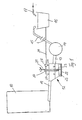
- Figure 1 shows a scale representation of a device according to the invention.
- FIG. 2 shows a diagrammatic illustration, likewise to scale, of a modified embodiment according to the invention.
- FIG. 1 shows a silo container 10, on which a conveyor 11 is located. Immediately following the conveyor is a siphon 12, which is connected to the conveyor 11 in a sealed manner. On the outlet side of the siphon there is a pipe 13 which leads to a reduction mill 14. The comminuted material is fed from the comminution mill 14 together with more or less water via a pipeline 15 to the mixing container 16. The mixing container 16 is also provided with a water supply line 17.
- line 13 and line 15 can have any shape. It is not necessary to maintain straight-line connections between the individual parts, for example line 15 could be two but also twenty meters long, which is not critical with regard to the conveyance because material that has been crushed in water here is promoted.
- the siphon 12 shown in FIG. 1 has a substantially cuboid structure, with a partition 20 in the middle, which does not, however, lead to the bottom of the siphon.
- a plate 22 with a plurality of radially arranged webs 23.
- the plate is connected to a drive shaft 21 which is mounted outside the siphon and is also driven outside the siphon, as is shown by an arrow.
- a certain water level is set in the siphon, as indicated by the two triangles.
- a line 24 leads from the mixing container 16 to a changeover valve 25, which can establish a connection from the line 24 either to a line 26 or to a line 27.
- a changeover valve 25 can establish a connection from the line 24 either to a line 26 or to a line 27.
- the two lines 26 and 27 can also each be connected to the mixing container 16 by separate lines, wherein further shut-off valves can be provided for each line.
- a certain amount of water is introduced into the mixing container 16 via the line 17. From there, water is introduced via line 24 into the siphon either on one or the other side. Finally, the conveyor 11 is activated so that material reaches the left side of the siphon 12 and is conveyed by the rotating plate 22 from the left to the right side. Depending on the amount of water added via line 27, more or less solid material is fed into the right-hand side of the siphon and finally passes via line 13 into the comminution mill. From there, the shredded material is fed together with water via line 15 into the mixing container. In the mixing container, the material conveyed in then settles out of the water, water in the desired amount being able to be conveyed into the siphon via line 24. Only after a sufficient amount of solids has been introduced into the mixing container 16 is the further conveying process stopped and the mixing device (not shown) in the mixing tank 16 activated.
- Fig. 2 shows a modified conveyor device according to the invention.
- This conveyor essentially consists of a cylindrical tube 36, which is connected at one end to the siphon 12 in a sealed manner and at the other end is connected to the bottom of the silo 10 in a sealed manner.
- nozzles 30 and 31 At the lower end of the silo or at the end of the pipe there are nozzles 30 and 31. Only two nozzles are shown, of course a large number of nozzles could be used, and movable or tumbling nozzles can also be used, so that when the nozzles 30 and 31 are started up by adding water via the lines 33 and 34 shown, a more or less conical area is removed from the material 37 located in the silo 10.
- the removed material can collect at the lower region of the silo 10 or at the beginning of the tube 36.
- a nozzle 32 is now supplied with pressurized water via a line 35, so that the accumulated material can be conveyed into the siphon.
- the conveyor device shown in FIG. 2 has only been outlined in broad outline. All types of nozzles or nozzle shapes can be used, it is also contemplated to pressurize the water in pulses so that the best possible removal effect is achieved. In any case, the nozzles 30 and 31, on the one hand, and the nozzles 32, on the other hand, have to be activated alternately, but this can easily be controlled via a predetermined program.
Landscapes
- Life Sciences & Earth Sciences (AREA)
- Environmental Sciences (AREA)
- Chemical & Material Sciences (AREA)
- Engineering & Computer Science (AREA)
- Food Science & Technology (AREA)
- Polymers & Plastics (AREA)
- Apparatuses For Bulk Treatment Of Fruits And Vegetables And Apparatuses For Preparing Feeds (AREA)
Priority Applications (1)
| Application Number | Priority Date | Filing Date | Title |
|---|---|---|---|
| AT81902315T ATE10152T1 (de) | 1980-08-16 | 1981-08-13 | Vorrichtung zur aufbereitung von viehfutter. |
Applications Claiming Priority (2)
| Application Number | Priority Date | Filing Date | Title |
|---|---|---|---|
| DE3031030 | 1980-08-16 | ||
| DE3031030A DE3031030C2 (de) | 1980-08-16 | 1980-08-16 | Vorrichtung zur Aufbereitung von Viehfutter |
Publications (2)
| Publication Number | Publication Date |
|---|---|
| EP0057716A1 EP0057716A1 (de) | 1982-08-18 |
| EP0057716B1 true EP0057716B1 (de) | 1984-11-07 |
Family
ID=6109772
Family Applications (1)
| Application Number | Title | Priority Date | Filing Date |
|---|---|---|---|
| EP81902315A Expired EP0057716B1 (de) | 1980-08-16 | 1981-08-13 | Vorrichtung zur aufbereitung von viehfutter |
Country Status (5)
| Country | Link |
|---|---|
| US (1) | US4464984A (da) |
| EP (1) | EP0057716B1 (da) |
| DE (1) | DE3031030C2 (da) |
| DK (1) | DK146751C (da) |
| WO (1) | WO1982000566A1 (da) |
Families Citing this family (5)
| Publication number | Priority date | Publication date | Assignee | Title |
|---|---|---|---|---|
| DE3315009C2 (de) * | 1983-04-26 | 1987-04-30 | Engelbrecht + Lemmerbrock Gmbh + Co, 4520 Melle | Verfahren zum Einlagern und zur Entnahme von Naßschrot aus einem Silo und Vorrichtung zur Durchführung des Verfahrens |
| DE3425655A1 (de) * | 1984-07-12 | 1986-01-23 | Engelbrecht + Lemmerbrock Gmbh + Co, 4520 Melle | Verfahren und vorrichtung zur herstellung von schwemmfutter aus geschrotetem ccm |
| DE3448070A1 (de) * | 1984-07-12 | 1986-11-27 | Engelbrecht + Lemmerbrock Gmbh + Co, 4520 Melle | Einrichtung zur herstellung eines schwemmfutters aus ccm-schrot-silage |
| DE3434381A1 (de) * | 1984-09-19 | 1986-03-27 | Engelbrecht + Lemmerbrock Gmbh + Co, 4520 Melle | Verfahren zur herstellung von schwemmfutter und anlage zur durchfuehrung des verfahrens |
| DE3541455A1 (de) * | 1985-11-23 | 1987-05-27 | Engelbrecht & Lemmerbrock | Anlage zur herstellung eines schwemmfutters aus ccm schrot |
Family Cites Families (10)
| Publication number | Priority date | Publication date | Assignee | Title |
|---|---|---|---|---|
| US2551216A (en) * | 1945-06-07 | 1951-05-01 | Smith Corp A O | Silo |
| US2821993A (en) * | 1956-08-08 | 1958-02-04 | Gilbert & Barker Mfg Co | Establishing and maintaining means for siphon connection between liquid storage tanks |
| DE1160791B (de) * | 1961-04-26 | 1964-01-02 | Iaelfaia App Vertriebs G M B H | Spritzkopf zum Schwemmen von Massenguetern, insbesondere von Feldfruechten, wie Zuckerrueben, Kartoffeln od. dgl. |
| US3140161A (en) * | 1961-10-25 | 1964-07-07 | Int Harvester Co | Crop storage and mechanical removal |
| DE1178634B (de) * | 1962-10-09 | 1964-09-24 | Franz Aschenbrenner Jun | Verfahren und Vorrichtung zum Austragen von Silagesaeften aus Gaerfuttersilos |
| US3251292A (en) * | 1964-11-30 | 1966-05-17 | Kenneth W Vaughan | Means for conserving the gases of oxidation and fermentation during mechanical unloading of silos and the like |
| US3487960A (en) * | 1967-10-11 | 1970-01-06 | Smith Harvestore Products | Transfer device for storage structures and the like |
| US3646874A (en) * | 1969-11-03 | 1972-03-07 | Smith Corp A O | Method and apparatus for storage atmosphere control |
| DE2515052A1 (de) * | 1975-04-07 | 1976-10-14 | Dipl Landw Helmut Riecken Fa | Vorrichtung zur entnahme von konservierungsgut aus einem behaelter |
| US4201348A (en) * | 1978-05-01 | 1980-05-06 | Deere & Company | Feed grinding and mixing apparatus |
-
1980
- 1980-08-16 DE DE3031030A patent/DE3031030C2/de not_active Expired
-
1981
- 1981-08-13 EP EP81902315A patent/EP0057716B1/de not_active Expired
- 1981-08-13 WO PCT/EP1981/000122 patent/WO1982000566A1/de not_active Ceased
- 1981-08-13 US US06/369,015 patent/US4464984A/en not_active Expired - Fee Related
-
1982
- 1982-04-15 DK DK168782A patent/DK146751C/da active IP Right Grant
Also Published As
| Publication number | Publication date |
|---|---|
| EP0057716A1 (de) | 1982-08-18 |
| DK146751C (da) | 1984-06-04 |
| US4464984A (en) | 1984-08-14 |
| DK146751B (da) | 1983-12-27 |
| DE3031030C2 (de) | 1985-05-15 |
| WO1982000566A1 (en) | 1982-03-04 |
| DK168782A (da) | 1982-04-15 |
| DE3031030A1 (de) | 1982-04-01 |
Similar Documents
| Publication | Publication Date | Title |
|---|---|---|
| DE2526462B2 (de) | Verfahren und Vorrichtung zum hydraulischen Fördern von Feststoffen | |
| DE1209931B (de) | Verfahren zur Herstellung von waessrigen ton- und/oder bentonithaltigen Aufschlaemmungen bestimmter Dichte | |
| EP0057716B1 (de) | Vorrichtung zur aufbereitung von viehfutter | |
| EP1541239A1 (de) | Vorrichtung zum Zerreissen von Feststoffen, Zumischen von Flüssigkeit und Fördern der erzeugten Suspension in eine Verarbeitungsanlage | |
| DE3441030A1 (de) | Verfahren und vorrichtung zur verhinderung eines verklumpens oder anhaeufens von pulverfoermigem granulat in einer anlage zur behandlung von leichtem, pulverfoermigem granulat | |
| DE102019205147A1 (de) | Verfahren zur Entleerung einer Vorrichtung zur Herstellung von Granulaten oder Extrudaten | |
| DE1181475B (de) | Futterkuchenpresse | |
| DE2309257A1 (de) | Granuliervorrichtung mit schneckenfoerderer | |
| CH507138A (de) | Einrichtung zum Fördern und Dosieren von pastösen, klebrigen und rieselfähigen Materialien | |
| DE3149147C2 (de) | Verfahren und Vorrichtung zur Herstellung von Futtermittel durch Naßeinlagerung in einem Silo | |
| DE2422963B1 (de) | Pneumatische Misch- und Abförderanlage für (ließfähige Schüttgüter | |
| DE6938983U (de) | Mischer fuer getreide und zusatzstoffe zur herstellung eines mischfutters | |
| DE3223198C2 (de) | Anlage zur kontinuierlichen Bereitung von Schwemmfutter | |
| DE8217795U1 (de) | Vorrichtung zur satzweisen Bereitung einer Schwemmfuttermenge | |
| EP0247342B1 (de) | Zerkleinerungsvorrichtung zur Herstellung einer pastösen Masse | |
| EP0367084B1 (de) | Vorrichtung zum Austragen und Vermischen von stückigem Material mit einer Flüssigkeit | |
| DE69003747T2 (de) | Entnahmefräse und Transportgerät. | |
| DE3146631C2 (da) | ||
| EP0112937A1 (de) | Anordnung zum Fördern von insbesondere schwerfliessenden Schüttgütern | |
| DE1901746B2 (de) | Rohrmuehle | |
| DE3322180C2 (de) | Vorrichtung zum Vermischen von körnigem oder stückigem Material mit einer Flüssigkeit | |
| DE3541704A1 (de) | Verfahren zum herstellen einer fuer die fluessigfuetterung geeigneten aufschwemmung aus silage und fluessigkeit und vorrichtung zur durchfuehrung des verfahrens | |
| CH605348A5 (en) | Pneumatic mixing and transport of powders | |
| DE2554244A1 (de) | Vorrichtung zum herstellen und zerkleinern von mischungen | |
| DE9405470U1 (de) | Vorrichtung zum Wiederaufbereiten von Restbeton mit einer Förderschnecke |
Legal Events
| Date | Code | Title | Description |
|---|---|---|---|
| PUAI | Public reference made under article 153(3) epc to a published international application that has entered the european phase |
Free format text: ORIGINAL CODE: 0009012 |
|
| AK | Designated contracting states |
Designated state(s): AT FR GB SE |
|
| 17P | Request for examination filed |
Effective date: 19820831 |
|
| GRAA | (expected) grant |
Free format text: ORIGINAL CODE: 0009210 |
|
| AK | Designated contracting states |
Designated state(s): AT FR GB SE |
|
| REF | Corresponds to: |
Ref document number: 10152 Country of ref document: AT Date of ref document: 19841115 Kind code of ref document: T |
|
| ET | Fr: translation filed | ||
| PLBE | No opposition filed within time limit |
Free format text: ORIGINAL CODE: 0009261 |
|
| STAA | Information on the status of an ep patent application or granted ep patent |
Free format text: STATUS: NO OPPOSITION FILED WITHIN TIME LIMIT |
|
| 26N | No opposition filed | ||
| PGFP | Annual fee paid to national office [announced via postgrant information from national office to epo] |
Ref country code: SE Payment date: 19900820 Year of fee payment: 10 |
|
| PGFP | Annual fee paid to national office [announced via postgrant information from national office to epo] |
Ref country code: FR Payment date: 19910612 Year of fee payment: 11 |
|
| PGFP | Annual fee paid to national office [announced via postgrant information from national office to epo] |
Ref country code: GB Payment date: 19910625 Year of fee payment: 11 |
|
| PGFP | Annual fee paid to national office [announced via postgrant information from national office to epo] |
Ref country code: AT Payment date: 19910628 Year of fee payment: 11 |
|
| PG25 | Lapsed in a contracting state [announced via postgrant information from national office to epo] |
Ref country code: SE Effective date: 19910814 |
|
| PG25 | Lapsed in a contracting state [announced via postgrant information from national office to epo] |
Ref country code: GB Effective date: 19920813 Ref country code: AT Effective date: 19920813 |
|
| GBPC | Gb: european patent ceased through non-payment of renewal fee |
Effective date: 19920813 |
|
| PG25 | Lapsed in a contracting state [announced via postgrant information from national office to epo] |
Ref country code: FR Effective date: 19930430 |
|
| REG | Reference to a national code |
Ref country code: FR Ref legal event code: ST |
|
| EUG | Se: european patent has lapsed |
Ref document number: 81902315.1 Effective date: 19920306 |