EP0056830A1 - Procédé pour éviter ou pour diminuer le risque que court une installation et son environnement à cause de mélanges en réaction - Google Patents
Procédé pour éviter ou pour diminuer le risque que court une installation et son environnement à cause de mélanges en réaction Download PDFInfo
- Publication number
- EP0056830A1 EP0056830A1 EP81100534A EP81100534A EP0056830A1 EP 0056830 A1 EP0056830 A1 EP 0056830A1 EP 81100534 A EP81100534 A EP 81100534A EP 81100534 A EP81100534 A EP 81100534A EP 0056830 A1 EP0056830 A1 EP 0056830A1
- Authority
- EP
- European Patent Office
- Prior art keywords
- reaction
- area
- container
- room area
- reactive
- Prior art date
- Legal status (The legal status is an assumption and is not a legal conclusion. Google has not performed a legal analysis and makes no representation as to the accuracy of the status listed.)
- Granted
Links
Images
Classifications
-
- G—PHYSICS
- G21—NUCLEAR PHYSICS; NUCLEAR ENGINEERING
- G21C—NUCLEAR REACTORS
- G21C9/00—Emergency protection arrangements structurally associated with the reactor, e.g. safety valves provided with pressure equalisation devices
-
- Y—GENERAL TAGGING OF NEW TECHNOLOGICAL DEVELOPMENTS; GENERAL TAGGING OF CROSS-SECTIONAL TECHNOLOGIES SPANNING OVER SEVERAL SECTIONS OF THE IPC; TECHNICAL SUBJECTS COVERED BY FORMER USPC CROSS-REFERENCE ART COLLECTIONS [XRACs] AND DIGESTS
- Y02—TECHNOLOGIES OR APPLICATIONS FOR MITIGATION OR ADAPTATION AGAINST CLIMATE CHANGE
- Y02E—REDUCTION OF GREENHOUSE GAS [GHG] EMISSIONS, RELATED TO ENERGY GENERATION, TRANSMISSION OR DISTRIBUTION
- Y02E30/00—Energy generation of nuclear origin
- Y02E30/30—Nuclear fission reactors
Definitions
- the invention relates to a method according to the preamble of patent claim 1.
- Light water reactors have a primary coolant system which contains "ordinary" water as the coolant.
- the coolant is used for moderation and dissipation of the thermal energy obtained in fission.
- the thermal energy absorbed by the coolant and released during nuclear fission is fed directly to turbines to drive them in the pressurized water reactor via a thermally coupled second circuit (secondary circuit).
- a break in a primary coolant line which is referred to as a coolant loss accident, is a design accident.
- the reactor experiences a rapid shutdown in the event of such a break.
- a coolant loss accident causes a) that the air in the safety container is initially displaced by the released water vapor into the upper dome space of the safety container, while the lower area of the safety container fills almost exclusively with water vapor.
- a coolant leakage accident leads to the fact that the majority of the air in the so-called pressure chamber of the safety container and a large part of the water vapor from this area of the safety container are first transferred to a second, the so-called condensation chamber, which is connected to the safety container by flow becomes.
- the water vapor that enters the water reservoir of the condensation chamber via immersion tubes is condensed out there.
- the temperatures of the reactor core will be high.
- the temperatures of the cladding tubes of the reactor rise core above 800 ° C, a strongly exotic oxidation sets in, in which considerable amounts of hydrogen are generated within a period of minutes.
- the zircon contained in the fuel rod cladding reacts with the water used as a coolant according to the reaction equation:
- the containment vessel is connected to a secondary container, so that exploiting Dende in the containment atmosphere in the secondary container can ausdeh B n. It has also been proposed to release the atmosphere from the safety container into the free atmosphere in a controlled manner via appropriate cleaning filter sections, but this is extremely problematic in the case of massive fission product release.
- the secondary container can be designed as a full pressure container or as a pressure reduction system.
- the cleaning filter section could be provided as an independent measure for the safety container or as a supplement to the secondary container.
- reaction-inhibiting additives are a fire extinguishing substance such as halon.
- a fire extinguishing substance such as halon.
- the inertization of the containment is already provided during normal operation, which is filled with nitrogen instead of air, which has considerable disadvantages in normal operation.
- the invention has for its object to provide a method for avoiding or reducing a hazard to a plant and its environment by chemically and / or physically reacting substances and release of pollutants, in particular by combustion of hydrogen in the safety container of a nuclear power plant and / or by release of fission products from it .
- the reactive substances are kept separate or separated and then kept separate in order to avoid a possible reaction.
- the areas of the safety container into which the oxygen is displaced during the first phase of the accident i.e. before the occurrence of the metal-water reaction (e.g. zircon)
- the metal-water reaction e.g. zircon
- the areas of the safety container into which the oxygen is displaced during the first phase of the accident are to be kept structurally almost completely (pressure reduction system) or at least clearly (plant rooms / operating rooms in the case of the full pressure safety container) .
- the so-called alternative concepts with secondary (additional) This is given in safety containers and / or filter sections or can be provided accordingly.
- locking devices are provided which prevent the oxygen-containing atmosphere located in or introduced into the second room area from being able to get into the first hydrogen-containing room area.
- the method according to the invention also makes it possible to counter a negative pressure load by introducing an inert gas into the system after the occurrence of an accident, in particular shortly before or after the reaction has taken place. If a hot gas, for example water vapor, is fed in, an undesirable thermal material stress may possibly be counteracted at the same time, in particular if this feed is activated shortly before the flammability limit is reached.
- the course of the accident can be characterized in that pollutants from the process engineering system first get into the atmosphere of the container surrounding the system before a reactive partner is added at a later point in time.
- the reaction partner containing the pollutants which is present anyway (e.g. air, is moved to a second, separate area and the atmosphere in the first area is replaced by inert gas).
- the reaction can possibly be prevented by moving the initially released products by rinsing a substance which prevents or at least ' delays or dampens the reaction in the first, particularly dangerous area.
- this can be done, similarly to the inert gas in chemical reactions, for example by flushing with neutron-absorbing gas (for example boron-containing water vapor).
- the method according to the invention thus represents a closed and also step-by-step set of instruments for averting dangers for technical systems (or their surroundings), which are distinguished by a particular risk potential due to the occurrence of pollutants with additional, possible enrichment of reactive partners.
- FIGS. 1 and 2 have so far only had a single, first safety container, which, however, can be supplemented by further systems, in particular a further safety container and / or special filter systems, as will be discussed for future, alternative concepts. So far, the prevention of overpressure failure of the actual (first) safety container has been considered.
- the method according to the invention can be used for all systems.
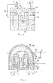
- a reactor pressure container 1 which contains the nuclear reactor, in which the nuclear reactions required for energy generation take place in a controlled manner.
- pressure accumulators 3 for an emergency and after-cooling system. These pressure accumulators 3 are connected to an emergency and after-cooling system 13, which also has the control elements required for the control of this system.
- a reactor quick shutdown system 4 which is arranged near the reactor pressure vessel 1, serves to enable the reactor to be shut down quickly.
- Rapid shutdown systems and emergency and after-cooling systems are used in so-called design accidents to bring the system into a safe state without causing an unauthorized radiation exposure to the environment. If such systems fail, an overheating of the core in the reactor pressure vessel 1 and subsequently larger amounts of hydrogen and fission products in the safety vessel 5 are to be expected than was the basis of the design. In the case of partial or complete meltdown, failure of the security container 5 cannot be ruled out at the same time.
- the meltdown is due to rapid and strong hydrogen formation, especially as a result of so-called metal-water reactions and at the same time due to the high temperatures and the destruction of the so-called internal safety barriers (fuel rod cladding tube, primary coolant system) due to the considerable release of fission products from the fuel or the melt into the Security container 5 atmosphere excellent.
- Safety containers and filter systems as well as hydrogen degradation systems have so far not been designed for this and in some cases are not to be adapted to such situations, so that a catastrophic impact on the system and the environment could not be prevented.
- first safety container 5 can be separated from one another in terms of flow technology by means of suitable devices (e.g. controllable flaps 43), or an additional, secondary container 14 must be able to be coupled.
- suitable devices e.g. controllable flaps 43
- an additional, secondary container 14 must be able to be coupled.
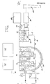
- This can be designed in a known manner as a full pressure container or as a pressure reduction system, as shown by way of example in FIG. 3 by the pressure reduction system 14. (Such measures are already being discussed as so-called alternative concepts).
- the Secondary container is provided at least one connecting line 7, which ends at one end in the interior of the security container 5 and at the other end in the chamber 15. At least one control valve 10 is provided in the connecting line 7, through which the flow through the connecting line 7 can be selectively opened or blocked.
- Both the chamber 15 and the space 12 located above the water reservoir are connected via e.g. Slides 26 and 27 are connected in terms of flow to a filter section 19, which in turn is connected in terms of flow to an exhaust air chimney 20.
- the water reservoir 16 can be connected to a wastewater treatment plant 18 via a connecting line 28.
- a connecting line 28 In the connecting line 28 a e.g. Slider 25 provided.
- the steam generator 2 is supplied with water via a connecting line 22 from main feed water pumps, not shown.
- a connecting line 22 from main feed water pumps, not shown.
- an emergency feed water system 11 is provided which is connected to the connecting line 22 in order to be able to supply the steam generators 2 with sufficient amounts of water.
- the steam generated by the steam generators 2 is led via a connecting line 21 to tubes, not shown.
- a live steam quick-closing slide 8 is provided, which serves to interrupt the live steam supply to the turbines if this is necessary.
- connecting lines 32 and 33 are provided, as shown, which lead from outside the security container 5 into the interior thereof.
- the connecting lines 32 and 33 are connected to a gas source 30 for an inert gas via control valves 34 and 35 and a feed line 31.
- Inert gas can be introduced into the interior of the safety container 5 from the gas source 30 via the connection system consisting of the parts 31 to 35.
- further connecting lines and control valves leading into the safety container can be provided if this is desired.
- valves 35 and 34 By selectively controlling the valves 35 and 34, it is possible to control the amount of gas that is to be introduced at various points within the containment 5, these points corresponding to the outlets of the connecting lines 32 and 33.
- an emergency feed system 40 which is connected to the interior of the safety container 5 via a connecting line 41.
- the gas flows into the safety container 5 at the outlet 42 of the connecting line 41.
- the following shows how the invention avoids a possible risk to the safety container in the event of a coolant loss accident.
- the control valves 10, 34 and 35 are opened.
- inert gas from the inert gas source 30 can reach the interior of the security container 5 via the connecting lines 31, 32 and 33.
- steam could also be taken as an inert gas feed from the secondary circuit of a pressurized water reactor and fed to the inert gas feed system 30 via line 44.
- the pressure of the atmosphere inside the safety container increases, so that the atmosphere in it can pass through the line 7 and the opened valve 10 into the chamber 15 of the secondary container.
- the atmosphere overflowing into the secondary container 14 from the interior of the safety container 5 contains not only the air originally present in the safety container, but also water vapor and possibly small amounts of hydrogen released in connection with the coolant loss accident.
- the proportion of air inside the containment has become so low that there is no risk that e.g. which can now quickly and in large quantities release hydrogen by ignition sources in such a way that there is a risk of combustion, explosion, quasi-detonation or detonation.
- the released hydrogen burns with the oxygen still contained in the containment, thereby reducing the pressure in the atmosphere inside the containment, this can be compensated for if necessary by further inflow of inert gas. It is advantageous at this point in time for the accident to occur if the pressure of the atmosphere inside the safety container 5 is kept at a value which is below the value which the atmosphere surrounding the safety container 5 has.
- the premature or subsequent closing of the control valve 10 or a throttling or the design as a one-way valve and possibly before combustion may increase the pressure in the outer so-called called annulus 46 may be required.
- the relative negative pressure present within the security container 5 ensures that no contaminated atmosphere can escape to the outside, but that leaks are directed inwards.
- the water vapor is condensed out by the water reservoir 16 and supplied to the wastewater treatment device 18 at a desired time. After a period of time, the length of which depends on the strength of the radioactivity of this atmosphere, the atmosphere remaining in the gaseous state can be released into the atmosphere via a cleaning filter section 19, which is followed by an exhaust air chimney 20.
- the advantages according to the invention can also be used in the case of old systems without the addition of additional safety containers and filter sections, that is to say using existing facilities such as primary safety containers and normal accident filters, if these are supplemented by shut-off devices 43 are so that, for example, the function of a secondary security container is taken over by a lockable area 47 of the primary safety container 5.
- the condensation of steam entering the secondary area 47 could be effected, for example, by external cooling of the safety container in the pressurized water reactor (FIG. 2) or spray systems inside.
- FIG. 2 pressurized water reactor
- these areas which are to be flow-controlled and / or controllably separated are preferably the area of the attachment spaces 48 on the one hand and the area of the operating spaces 47 on the other, which are separated, for example, by overflow flaps 43 at the upper ends of the steam generator towers.
- the realization of the second safety container in the form of a pressure reduction system has the expected cost advantages as well as the fact that this enables both an almost unlimited flushing of the primary safety container with steam, and at the same time the water reserve can be used as a condensing gas scrubber, which means both in terms of Pressure regulation in both safety containers and for the application of fission product filters, particularly favorable conditions are created.
Landscapes
- Physics & Mathematics (AREA)
- Engineering & Computer Science (AREA)
- Plasma & Fusion (AREA)
- General Engineering & Computer Science (AREA)
- High Energy & Nuclear Physics (AREA)
- Structure Of Emergency Protection For Nuclear Reactors (AREA)
- Developing Agents For Electrophotography (AREA)
- Indole Compounds (AREA)
- Heat Sensitive Colour Forming Recording (AREA)
- Physical Or Chemical Processes And Apparatus (AREA)
- Catalysts (AREA)
- Exhaust Gas Treatment By Means Of Catalyst (AREA)
Priority Applications (7)
| Application Number | Priority Date | Filing Date | Title |
|---|---|---|---|
| DE8181100534T DE3177046D1 (en) | 1981-01-25 | 1981-01-25 | Hazard avoiding or diminishing method for an installation and its environment due to reacting mixtures |
| EP81100534A EP0056830B2 (fr) | 1981-01-25 | 1981-01-25 | Procédé pour éviter ou pour diminuer le risque que court une installation et son environnement à cause de mélanges en réaction |
| AT81100534T ATE42651T1 (de) | 1981-01-25 | 1981-01-25 | Verfahren zum vermeiden oder verringern einer gefaehrdung einer anlage und deren umgebung durch reagierende gemische. |
| FI820185A FI820185A7 (fi) | 1981-01-25 | 1982-01-21 | Menetelmä laitteiston ja sen ympäristön vaaralle alttiiksi joutumisen välttämiseksi tai pienentämiseksi reagoireagoivilla seoksilla. |
| JP57009921A JPS57156591A (en) | 1981-01-25 | 1982-01-25 | Method of decreasing or protecting danger against reactive mixture system and its circumference |
| CA000394831A CA1188432A (fr) | 1981-01-25 | 1982-01-25 | Methode de prevention ou de reduction des dangers engendres par un systeme sujet a un accident |
| US06/756,816 US4797249A (en) | 1981-01-25 | 1985-07-18 | Process for precluding or reducing the danger to a system and the surroundings thereof by reactive mixtures |
Applications Claiming Priority (1)
| Application Number | Priority Date | Filing Date | Title |
|---|---|---|---|
| EP81100534A EP0056830B2 (fr) | 1981-01-25 | 1981-01-25 | Procédé pour éviter ou pour diminuer le risque que court une installation et son environnement à cause de mélanges en réaction |
Publications (3)
| Publication Number | Publication Date |
|---|---|
| EP0056830A1 true EP0056830A1 (fr) | 1982-08-04 |
| EP0056830B1 EP0056830B1 (fr) | 1989-04-26 |
| EP0056830B2 EP0056830B2 (fr) | 1993-12-15 |
Family
ID=8187548
Family Applications (1)
| Application Number | Title | Priority Date | Filing Date |
|---|---|---|---|
| EP81100534A Expired - Lifetime EP0056830B2 (fr) | 1981-01-25 | 1981-01-25 | Procédé pour éviter ou pour diminuer le risque que court une installation et son environnement à cause de mélanges en réaction |
Country Status (7)
| Country | Link |
|---|---|
| US (1) | US4797249A (fr) |
| EP (1) | EP0056830B2 (fr) |
| JP (1) | JPS57156591A (fr) |
| AT (1) | ATE42651T1 (fr) |
| CA (1) | CA1188432A (fr) |
| DE (1) | DE3177046D1 (fr) |
| FI (1) | FI820185A7 (fr) |
Cited By (6)
| Publication number | Priority date | Publication date | Assignee | Title |
|---|---|---|---|---|
| EP0070037A3 (en) * | 1981-07-14 | 1984-02-08 | Hermann Dr. Jahn | Process for preventing or checking the blending of the atmosphere existent in a confined space with a gaseous material present in that space |
| EP0263993A3 (en) * | 1986-10-17 | 1988-07-20 | Kernforschungszentrum Karlsruhe Gmbh | Pressure suppression system for a security confinement of a nuclear reactor |
| EP0285845A1 (fr) * | 1987-03-23 | 1988-10-12 | Siemens Aktiengesellschaft | Méthode et dispositif pour la dépressurisation d'une centrale nucléaire |
| EP0290028A1 (fr) * | 1987-05-08 | 1988-11-09 | Siemens Aktiengesellschaft | Système de décompression et dispositif de filtrage pour des installations nucléaires, notamment pour des réacteurs à eau sous pression |
| DE3927958A1 (de) * | 1988-09-17 | 1990-03-22 | Gemeinschaftskernkraftwerk Nec | Verfahren zur vermeidung von gefahren bei stoerfaellen wassergekuehlter kernreaktoren und einrichtung hierzu |
| EP0466052A1 (fr) * | 1990-07-06 | 1992-01-15 | Hermann Dr. Jahn | Procédé de réduction des risques en cas d'accident |
Families Citing this family (6)
| Publication number | Priority date | Publication date | Assignee | Title |
|---|---|---|---|---|
| DE59300973D1 (de) * | 1993-08-24 | 1995-12-21 | Anlagen Und Reaktorsicherheit | Vorrichtung zur passiven Inertisierung des Gasgemisches im Sicherheitsbehälter eines Kernkraftwerkes. |
| US6262328B1 (en) | 1999-06-11 | 2001-07-17 | Westinghouse Savannah River Company | Container and method for absorbing and reducing hydrogen concentration |
| JP5006178B2 (ja) * | 2007-12-21 | 2012-08-22 | 株式会社東芝 | 原子炉格納容器およびそれを用いた原子力プラント |
| US9502144B2 (en) * | 2012-07-06 | 2016-11-22 | Westinghouse Electric Company Llc | Filter for a nuclear reactor containment ventilation system |
| JP5898018B2 (ja) * | 2012-08-27 | 2016-04-06 | 日立Geニュークリア・エナジー株式会社 | 原子炉格納容器のフィルタベント装置および原子炉格納容器 |
| BR112019006253B1 (pt) * | 2016-11-28 | 2022-10-04 | Framatome Gmbh | Instalação de energia nuclear compreendendo uma contenção e um sistema de ventilação de contenção |
Citations (8)
| Publication number | Priority date | Publication date | Assignee | Title |
|---|---|---|---|---|
| GB862624A (en) * | 1958-07-09 | 1961-03-15 | Atomic Energy Authority Uk | Improvements in or relating to nuclear reactor installations |
| US3115450A (en) * | 1959-02-24 | 1963-12-24 | Gen Electric | Nuclear reactor containment apparatus |
| US3307913A (en) * | 1962-07-27 | 1967-03-07 | Stone & Webster Eng Corp | Vacuum producing apparatus for containment vessels |
| FR2042604A1 (fr) * | 1969-05-13 | 1971-02-12 | Babcock & Wilcox Co | |
| DE2115264A1 (en) * | 1971-03-30 | 1972-10-05 | Kernforschung Gmbh Ges Fuer | Pressure reducing containment - for liquid sodium reactor plants |
| US3865688A (en) * | 1970-08-05 | 1975-02-11 | Frank W Kleimola | Passive containment system |
| DE2805476A1 (de) * | 1978-02-09 | 1979-08-23 | Hermann Dipl Ing Jahn | Verfahren zum aufloesen von lokalen gaskonzentrationen in uebereinander geschichteten atmosphaeren |
| US4210614A (en) * | 1970-08-05 | 1980-07-01 | Nucledyne Engineering Corp. | Passive containment system |
Family Cites Families (5)
| Publication number | Priority date | Publication date | Assignee | Title |
|---|---|---|---|---|
| GB1092536A (en) * | 1964-05-25 | 1967-11-29 | Atomic Energy Authority Uk | Improvements in or relating to nuclear reactors |
| JPS424640Y1 (fr) * | 1964-11-07 | 1967-03-11 | ||
| US3889707A (en) * | 1971-11-19 | 1975-06-17 | Gen Atomic Co | Pressure relief system for a nuclear reactor |
| DE2633113C2 (de) * | 1976-07-23 | 1984-08-30 | Kernforschungszentrum Karlsruhe Gmbh, 7500 Karlsruhe | Verfahren zur Vermeidung von Gefahren, die bei Störfällen an wassergekühlten Kernreaktoren entstehen |
| DE3127804A1 (de) * | 1981-07-14 | 1983-02-10 | Schweiger, W., Dr.-Ing., 8039 Puchheim | Verfahren zum vermeiden oder hemmen einer durchmischung der in einem abgeschlossenen raum vorhandenen atmosphaere mit einem sich in dem raum befindenden gasfoermigen stoff |
-
1981
- 1981-01-25 DE DE8181100534T patent/DE3177046D1/de not_active Expired
- 1981-01-25 EP EP81100534A patent/EP0056830B2/fr not_active Expired - Lifetime
- 1981-01-25 AT AT81100534T patent/ATE42651T1/de not_active IP Right Cessation
-
1982
- 1982-01-21 FI FI820185A patent/FI820185A7/fi not_active Application Discontinuation
- 1982-01-25 CA CA000394831A patent/CA1188432A/fr not_active Expired
- 1982-01-25 JP JP57009921A patent/JPS57156591A/ja active Pending
-
1985
- 1985-07-18 US US06/756,816 patent/US4797249A/en not_active Expired - Lifetime
Patent Citations (8)
| Publication number | Priority date | Publication date | Assignee | Title |
|---|---|---|---|---|
| GB862624A (en) * | 1958-07-09 | 1961-03-15 | Atomic Energy Authority Uk | Improvements in or relating to nuclear reactor installations |
| US3115450A (en) * | 1959-02-24 | 1963-12-24 | Gen Electric | Nuclear reactor containment apparatus |
| US3307913A (en) * | 1962-07-27 | 1967-03-07 | Stone & Webster Eng Corp | Vacuum producing apparatus for containment vessels |
| FR2042604A1 (fr) * | 1969-05-13 | 1971-02-12 | Babcock & Wilcox Co | |
| US3865688A (en) * | 1970-08-05 | 1975-02-11 | Frank W Kleimola | Passive containment system |
| US4210614A (en) * | 1970-08-05 | 1980-07-01 | Nucledyne Engineering Corp. | Passive containment system |
| DE2115264A1 (en) * | 1971-03-30 | 1972-10-05 | Kernforschung Gmbh Ges Fuer | Pressure reducing containment - for liquid sodium reactor plants |
| DE2805476A1 (de) * | 1978-02-09 | 1979-08-23 | Hermann Dipl Ing Jahn | Verfahren zum aufloesen von lokalen gaskonzentrationen in uebereinander geschichteten atmosphaeren |
Non-Patent Citations (1)
| Title |
|---|
| Nuclear Safety, Band 15, Nr. 2, Marz/April 1974 G.E. Wade: "Evolution and Current Status of the BWR Containment System", seiten 163-173. *seite 171 "Hydrogen Control Systems"; Figur 6* * |
Cited By (8)
| Publication number | Priority date | Publication date | Assignee | Title |
|---|---|---|---|---|
| EP0070037A3 (en) * | 1981-07-14 | 1984-02-08 | Hermann Dr. Jahn | Process for preventing or checking the blending of the atmosphere existent in a confined space with a gaseous material present in that space |
| EP0263993A3 (en) * | 1986-10-17 | 1988-07-20 | Kernforschungszentrum Karlsruhe Gmbh | Pressure suppression system for a security confinement of a nuclear reactor |
| EP0285845A1 (fr) * | 1987-03-23 | 1988-10-12 | Siemens Aktiengesellschaft | Méthode et dispositif pour la dépressurisation d'une centrale nucléaire |
| US4873050A (en) * | 1987-03-23 | 1989-10-10 | Siemens Aktiengesellschaft | Method and apparatus for pressure relief of a nuclear power plant |
| EP0290028A1 (fr) * | 1987-05-08 | 1988-11-09 | Siemens Aktiengesellschaft | Système de décompression et dispositif de filtrage pour des installations nucléaires, notamment pour des réacteurs à eau sous pression |
| WO1988009039A1 (fr) * | 1987-05-08 | 1988-11-17 | Siemens Aktiengesellschaft | Systeme de detente et de filtration pour reacteurs a eau pressurisee |
| DE3927958A1 (de) * | 1988-09-17 | 1990-03-22 | Gemeinschaftskernkraftwerk Nec | Verfahren zur vermeidung von gefahren bei stoerfaellen wassergekuehlter kernreaktoren und einrichtung hierzu |
| EP0466052A1 (fr) * | 1990-07-06 | 1992-01-15 | Hermann Dr. Jahn | Procédé de réduction des risques en cas d'accident |
Also Published As
| Publication number | Publication date |
|---|---|
| ATE42651T1 (de) | 1989-05-15 |
| FI820185L (fi) | 1982-07-26 |
| JPS57156591A (en) | 1982-09-27 |
| FI820185A7 (fi) | 1982-07-26 |
| CA1188432A (fr) | 1985-06-04 |
| EP0056830B2 (fr) | 1993-12-15 |
| US4797249A (en) | 1989-01-10 |
| DE3177046D1 (en) | 1989-06-01 |
| EP0056830B1 (fr) | 1989-04-26 |
Similar Documents
| Publication | Publication Date | Title |
|---|---|---|
| DE3435255C2 (fr) | ||
| DE102012211897B3 (de) | Kerntechnische Anlage mit einer Sicherheitshülle und mit einem Druckentlastungssystem | |
| EP0056830B2 (fr) | Procédé pour éviter ou pour diminuer le risque que court une installation et son environnement à cause de mélanges en réaction | |
| DE2241303C3 (de) | Anordnung zur druckmindernden Dekontaminierungssprühung für eine Kernreaktoranlage | |
| DE69010977T2 (de) | Indirektes passives Kühlsystem für Kernreaktoren mit Flüssigmetallkühlung. | |
| DE102006010826A1 (de) | Kerntechnische Anlage sowie Verschlussvorrichtung für deren Sicherheitsbehälter | |
| DE3212265C2 (de) | Verfahren und Einrichtung zur gezielten Aktivitätsableitung aus dem Reaktorschutzgebäude einer gasgekühlten Kernkraftanlage | |
| DE2441999A1 (de) | Verfahren zur staendigen kontrolle des zweischalen-reaktorgefaesses eines reaktors und reaktor zur anwendung dieses verfahrens | |
| DE1957701A1 (de) | Steuersystem fuer Kernreaktoren | |
| EP1233423B1 (fr) | Dispositif pour le refroidissement et la protection de la cuve sous pression d'un réacteur en cas de fusion du coeur | |
| DE2516123B2 (de) | Verfahren zum Abführen der Zerfallswärme radioaktiver Spaltprodukte | |
| EP0466052B1 (fr) | Procédé de réduction des risques en cas d'accident | |
| EP0070037A2 (fr) | Procédé pour prévenir ou ralentir le mélange d'un atmosphère présent dans une espace fermée avec un matériel gazeux, également présent dans ladite espace | |
| EP1497835B2 (fr) | Système de stockage intermédiaire destiné à des éléments de combustible provenant d'une centrale nucléaire et procédé d'utilisation d'un tel système de stockage intermédiaire | |
| DE2519273C3 (de) | Verfahren zum Wärmeschutz des Deckenreflektors eines Hochtemperatur-Reaktots | |
| DE3446141A1 (de) | In einem stahldruckbehaelter untergebrachte kernreaktoranlage mit einem gasgekuehlten ht-kleinreaktor | |
| DE3335268C2 (fr) | ||
| DE1105531B (de) | Durch Graphit moderierter Kernreaktor mit positivem Temperaturkoeffizienten des Moderatoreinflusses auf die Reaktivitaet | |
| DE2805476C3 (de) | Verfahren zum Auflösen von lokalen Gaskonzentrationen in übereinander geschichteten Atmosphären | |
| WO1996020486A1 (fr) | Dispositif de refroidissement d'urgence pour centrale nucleaire et procede de refroidissement d'urgence du c×ur d'un reacteur | |
| DE3212322A1 (de) | Verfahren zur beherrschung von auslegungs- und hypothetischen stoerfaellen in einem kernkraftwerk | |
| DE2430725C3 (de) | Überdruckentlastung für eine Kernreaktoranlage | |
| DE2129169A1 (de) | Kernreaktor | |
| DE2945964C2 (fr) | ||
| DE2154831C3 (de) | Vorrichtung zum Abstützen des Moderatoraufbaus eines Kernreaktors |
Legal Events
| Date | Code | Title | Description |
|---|---|---|---|
| PUAI | Public reference made under article 153(3) epc to a published international application that has entered the european phase |
Free format text: ORIGINAL CODE: 0009012 |
|
| AK | Designated contracting states |
Designated state(s): AT BE CH DE FR GB IT LU NL SE |
|
| 17P | Request for examination filed |
Effective date: 19830204 |
|
| RAP1 | Party data changed (applicant data changed or rights of an application transferred) |
Owner name: JAHN, HERMANN, DR. |
|
| RIN1 | Information on inventor provided before grant (corrected) |
Inventor name: SCHWEIGER, WILLY, DR.-ING. |
|
| GRAA | (expected) grant |
Free format text: ORIGINAL CODE: 0009210 |
|
| AK | Designated contracting states |
Kind code of ref document: B1 Designated state(s): AT BE CH DE FR GB IT LI LU NL SE |
|
| PG25 | Lapsed in a contracting state [announced via postgrant information from national office to epo] |
Ref country code: SE Effective date: 19890426 Ref country code: NL Effective date: 19890426 Ref country code: IT Free format text: LAPSE BECAUSE OF FAILURE TO SUBMIT A TRANSLATION OF THE DESCRIPTION OR TO PAY THE FEE WITHIN THE PRESCRIBED TIME-LIMIT;WARNING: LAPSES OF ITALIAN PATENTS WITH EFFECTIVE DATE BEFORE 2007 MAY HAVE OCCURRED AT ANY TIME BEFORE 2007. THE CORRECT EFFECTIVE DATE MAY BE DIFFERENT FROM THE ONE RECORDED. Effective date: 19890426 |
|
| REF | Corresponds to: |
Ref document number: 42651 Country of ref document: AT Date of ref document: 19890515 Kind code of ref document: T |
|
| GBT | Gb: translation of ep patent filed (gb section 77(6)(a)/1977) | ||
| REF | Corresponds to: |
Ref document number: 3177046 Country of ref document: DE Date of ref document: 19890601 |
|
| ET | Fr: translation filed | ||
| NLV1 | Nl: lapsed or annulled due to failure to fulfill the requirements of art. 29p and 29m of the patents act | ||
| PGFP | Annual fee paid to national office [announced via postgrant information from national office to epo] |
Ref country code: GB Payment date: 19891231 Year of fee payment: 10 |
|
| PGFP | Annual fee paid to national office [announced via postgrant information from national office to epo] |
Ref country code: BE Payment date: 19900111 Year of fee payment: 10 |
|
| PG25 | Lapsed in a contracting state [announced via postgrant information from national office to epo] |
Ref country code: AT Effective date: 19900125 |
|
| PLBI | Opposition filed |
Free format text: ORIGINAL CODE: 0009260 |
|
| PG25 | Lapsed in a contracting state [announced via postgrant information from national office to epo] |
Ref country code: LU Free format text: LAPSE BECAUSE OF NON-PAYMENT OF DUE FEES Effective date: 19900131 |
|
| PGFP | Annual fee paid to national office [announced via postgrant information from national office to epo] |
Ref country code: CH Payment date: 19900206 Year of fee payment: 10 |
|
| 26 | Opposition filed |
Opponent name: SIEMENS AKTIENGESELLSCHAFT, BERLIN UND MUENCHEN Effective date: 19900123 |
|
| PG25 | Lapsed in a contracting state [announced via postgrant information from national office to epo] |
Ref country code: GB Effective date: 19910125 |
|
| PG25 | Lapsed in a contracting state [announced via postgrant information from national office to epo] |
Ref country code: LI Effective date: 19910131 Ref country code: CH Effective date: 19910131 Ref country code: BE Effective date: 19910131 |
|
| GBPC | Gb: european patent ceased through non-payment of renewal fee | ||
| REG | Reference to a national code |
Ref country code: CH Ref legal event code: PL |
|
| PUAH | Patent maintained in amended form |
Free format text: ORIGINAL CODE: 0009272 |
|
| STAA | Information on the status of an ep patent application or granted ep patent |
Free format text: STATUS: PATENT MAINTAINED AS AMENDED |
|
| 27A | Patent maintained in amended form |
Effective date: 19931215 |
|
| AK | Designated contracting states |
Kind code of ref document: B2 Designated state(s): AT BE CH DE FR GB IT LI LU NL SE |
|
| ET3 | Fr: translation filed ** decision concerning opposition | ||
| PGFP | Annual fee paid to national office [announced via postgrant information from national office to epo] |
Ref country code: FR Payment date: 19990118 Year of fee payment: 19 |
|
| PGFP | Annual fee paid to national office [announced via postgrant information from national office to epo] |
Ref country code: DE Payment date: 19990311 Year of fee payment: 19 |
|
| PG25 | Lapsed in a contracting state [announced via postgrant information from national office to epo] |
Ref country code: FR Free format text: LAPSE BECAUSE OF NON-PAYMENT OF DUE FEES Effective date: 20000929 |
|
| PG25 | Lapsed in a contracting state [announced via postgrant information from national office to epo] |
Ref country code: DE Free format text: LAPSE BECAUSE OF NON-PAYMENT OF DUE FEES Effective date: 20001101 |
|
| REG | Reference to a national code |
Ref country code: FR Ref legal event code: ST |
|
| APAH | Appeal reference modified |
Free format text: ORIGINAL CODE: EPIDOSCREFNO |