EP0056830A1 - Hazard avoiding or diminishing method for an installation and its environment due to reacting mixtures - Google Patents
Hazard avoiding or diminishing method for an installation and its environment due to reacting mixtures Download PDFInfo
- Publication number
- EP0056830A1 EP0056830A1 EP81100534A EP81100534A EP0056830A1 EP 0056830 A1 EP0056830 A1 EP 0056830A1 EP 81100534 A EP81100534 A EP 81100534A EP 81100534 A EP81100534 A EP 81100534A EP 0056830 A1 EP0056830 A1 EP 0056830A1
- Authority
- EP
- European Patent Office
- Prior art keywords
- reaction
- area
- container
- room area
- reactive
- Prior art date
- Legal status (The legal status is an assumption and is not a legal conclusion. Google has not performed a legal analysis and makes no representation as to the accuracy of the status listed.)
- Granted
Links
Images
Classifications
-
- G—PHYSICS
- G21—NUCLEAR PHYSICS; NUCLEAR ENGINEERING
- G21C—NUCLEAR REACTORS
- G21C9/00—Emergency protection arrangements structurally associated with the reactor, e.g. safety valves provided with pressure equalisation devices
-
- Y—GENERAL TAGGING OF NEW TECHNOLOGICAL DEVELOPMENTS; GENERAL TAGGING OF CROSS-SECTIONAL TECHNOLOGIES SPANNING OVER SEVERAL SECTIONS OF THE IPC; TECHNICAL SUBJECTS COVERED BY FORMER USPC CROSS-REFERENCE ART COLLECTIONS [XRACs] AND DIGESTS
- Y02—TECHNOLOGIES OR APPLICATIONS FOR MITIGATION OR ADAPTATION AGAINST CLIMATE CHANGE
- Y02E—REDUCTION OF GREENHOUSE GAS [GHG] EMISSIONS, RELATED TO ENERGY GENERATION, TRANSMISSION OR DISTRIBUTION
- Y02E30/00—Energy generation of nuclear origin
- Y02E30/30—Nuclear fission reactors
Definitions
- the invention relates to a method according to the preamble of patent claim 1.
- Light water reactors have a primary coolant system which contains "ordinary" water as the coolant.
- the coolant is used for moderation and dissipation of the thermal energy obtained in fission.
- the thermal energy absorbed by the coolant and released during nuclear fission is fed directly to turbines to drive them in the pressurized water reactor via a thermally coupled second circuit (secondary circuit).
- a break in a primary coolant line which is referred to as a coolant loss accident, is a design accident.
- the reactor experiences a rapid shutdown in the event of such a break.
- a coolant loss accident causes a) that the air in the safety container is initially displaced by the released water vapor into the upper dome space of the safety container, while the lower area of the safety container fills almost exclusively with water vapor.
- a coolant leakage accident leads to the fact that the majority of the air in the so-called pressure chamber of the safety container and a large part of the water vapor from this area of the safety container are first transferred to a second, the so-called condensation chamber, which is connected to the safety container by flow becomes.
- the water vapor that enters the water reservoir of the condensation chamber via immersion tubes is condensed out there.
- the temperatures of the reactor core will be high.
- the temperatures of the cladding tubes of the reactor rise core above 800 ° C, a strongly exotic oxidation sets in, in which considerable amounts of hydrogen are generated within a period of minutes.
- the zircon contained in the fuel rod cladding reacts with the water used as a coolant according to the reaction equation:
- the containment vessel is connected to a secondary container, so that exploiting Dende in the containment atmosphere in the secondary container can ausdeh B n. It has also been proposed to release the atmosphere from the safety container into the free atmosphere in a controlled manner via appropriate cleaning filter sections, but this is extremely problematic in the case of massive fission product release.
- the secondary container can be designed as a full pressure container or as a pressure reduction system.
- the cleaning filter section could be provided as an independent measure for the safety container or as a supplement to the secondary container.
- reaction-inhibiting additives are a fire extinguishing substance such as halon.
- a fire extinguishing substance such as halon.
- the inertization of the containment is already provided during normal operation, which is filled with nitrogen instead of air, which has considerable disadvantages in normal operation.
- the invention has for its object to provide a method for avoiding or reducing a hazard to a plant and its environment by chemically and / or physically reacting substances and release of pollutants, in particular by combustion of hydrogen in the safety container of a nuclear power plant and / or by release of fission products from it .
- the reactive substances are kept separate or separated and then kept separate in order to avoid a possible reaction.
- the areas of the safety container into which the oxygen is displaced during the first phase of the accident i.e. before the occurrence of the metal-water reaction (e.g. zircon)
- the metal-water reaction e.g. zircon
- the areas of the safety container into which the oxygen is displaced during the first phase of the accident are to be kept structurally almost completely (pressure reduction system) or at least clearly (plant rooms / operating rooms in the case of the full pressure safety container) .
- the so-called alternative concepts with secondary (additional) This is given in safety containers and / or filter sections or can be provided accordingly.
- locking devices are provided which prevent the oxygen-containing atmosphere located in or introduced into the second room area from being able to get into the first hydrogen-containing room area.
- the method according to the invention also makes it possible to counter a negative pressure load by introducing an inert gas into the system after the occurrence of an accident, in particular shortly before or after the reaction has taken place. If a hot gas, for example water vapor, is fed in, an undesirable thermal material stress may possibly be counteracted at the same time, in particular if this feed is activated shortly before the flammability limit is reached.
- the course of the accident can be characterized in that pollutants from the process engineering system first get into the atmosphere of the container surrounding the system before a reactive partner is added at a later point in time.
- the reaction partner containing the pollutants which is present anyway (e.g. air, is moved to a second, separate area and the atmosphere in the first area is replaced by inert gas).
- the reaction can possibly be prevented by moving the initially released products by rinsing a substance which prevents or at least ' delays or dampens the reaction in the first, particularly dangerous area.
- this can be done, similarly to the inert gas in chemical reactions, for example by flushing with neutron-absorbing gas (for example boron-containing water vapor).
- the method according to the invention thus represents a closed and also step-by-step set of instruments for averting dangers for technical systems (or their surroundings), which are distinguished by a particular risk potential due to the occurrence of pollutants with additional, possible enrichment of reactive partners.
- FIGS. 1 and 2 have so far only had a single, first safety container, which, however, can be supplemented by further systems, in particular a further safety container and / or special filter systems, as will be discussed for future, alternative concepts. So far, the prevention of overpressure failure of the actual (first) safety container has been considered.
- the method according to the invention can be used for all systems.
- a reactor pressure container 1 which contains the nuclear reactor, in which the nuclear reactions required for energy generation take place in a controlled manner.
- pressure accumulators 3 for an emergency and after-cooling system. These pressure accumulators 3 are connected to an emergency and after-cooling system 13, which also has the control elements required for the control of this system.
- a reactor quick shutdown system 4 which is arranged near the reactor pressure vessel 1, serves to enable the reactor to be shut down quickly.
- Rapid shutdown systems and emergency and after-cooling systems are used in so-called design accidents to bring the system into a safe state without causing an unauthorized radiation exposure to the environment. If such systems fail, an overheating of the core in the reactor pressure vessel 1 and subsequently larger amounts of hydrogen and fission products in the safety vessel 5 are to be expected than was the basis of the design. In the case of partial or complete meltdown, failure of the security container 5 cannot be ruled out at the same time.
- the meltdown is due to rapid and strong hydrogen formation, especially as a result of so-called metal-water reactions and at the same time due to the high temperatures and the destruction of the so-called internal safety barriers (fuel rod cladding tube, primary coolant system) due to the considerable release of fission products from the fuel or the melt into the Security container 5 atmosphere excellent.
- Safety containers and filter systems as well as hydrogen degradation systems have so far not been designed for this and in some cases are not to be adapted to such situations, so that a catastrophic impact on the system and the environment could not be prevented.
- first safety container 5 can be separated from one another in terms of flow technology by means of suitable devices (e.g. controllable flaps 43), or an additional, secondary container 14 must be able to be coupled.
- suitable devices e.g. controllable flaps 43
- an additional, secondary container 14 must be able to be coupled.
- This can be designed in a known manner as a full pressure container or as a pressure reduction system, as shown by way of example in FIG. 3 by the pressure reduction system 14. (Such measures are already being discussed as so-called alternative concepts).
- the Secondary container is provided at least one connecting line 7, which ends at one end in the interior of the security container 5 and at the other end in the chamber 15. At least one control valve 10 is provided in the connecting line 7, through which the flow through the connecting line 7 can be selectively opened or blocked.
- Both the chamber 15 and the space 12 located above the water reservoir are connected via e.g. Slides 26 and 27 are connected in terms of flow to a filter section 19, which in turn is connected in terms of flow to an exhaust air chimney 20.
- the water reservoir 16 can be connected to a wastewater treatment plant 18 via a connecting line 28.
- a connecting line 28 In the connecting line 28 a e.g. Slider 25 provided.
- the steam generator 2 is supplied with water via a connecting line 22 from main feed water pumps, not shown.
- a connecting line 22 from main feed water pumps, not shown.
- an emergency feed water system 11 is provided which is connected to the connecting line 22 in order to be able to supply the steam generators 2 with sufficient amounts of water.
- the steam generated by the steam generators 2 is led via a connecting line 21 to tubes, not shown.
- a live steam quick-closing slide 8 is provided, which serves to interrupt the live steam supply to the turbines if this is necessary.
- connecting lines 32 and 33 are provided, as shown, which lead from outside the security container 5 into the interior thereof.
- the connecting lines 32 and 33 are connected to a gas source 30 for an inert gas via control valves 34 and 35 and a feed line 31.
- Inert gas can be introduced into the interior of the safety container 5 from the gas source 30 via the connection system consisting of the parts 31 to 35.
- further connecting lines and control valves leading into the safety container can be provided if this is desired.
- valves 35 and 34 By selectively controlling the valves 35 and 34, it is possible to control the amount of gas that is to be introduced at various points within the containment 5, these points corresponding to the outlets of the connecting lines 32 and 33.
- an emergency feed system 40 which is connected to the interior of the safety container 5 via a connecting line 41.
- the gas flows into the safety container 5 at the outlet 42 of the connecting line 41.
- the following shows how the invention avoids a possible risk to the safety container in the event of a coolant loss accident.
- the control valves 10, 34 and 35 are opened.
- inert gas from the inert gas source 30 can reach the interior of the security container 5 via the connecting lines 31, 32 and 33.
- steam could also be taken as an inert gas feed from the secondary circuit of a pressurized water reactor and fed to the inert gas feed system 30 via line 44.
- the pressure of the atmosphere inside the safety container increases, so that the atmosphere in it can pass through the line 7 and the opened valve 10 into the chamber 15 of the secondary container.
- the atmosphere overflowing into the secondary container 14 from the interior of the safety container 5 contains not only the air originally present in the safety container, but also water vapor and possibly small amounts of hydrogen released in connection with the coolant loss accident.
- the proportion of air inside the containment has become so low that there is no risk that e.g. which can now quickly and in large quantities release hydrogen by ignition sources in such a way that there is a risk of combustion, explosion, quasi-detonation or detonation.
- the released hydrogen burns with the oxygen still contained in the containment, thereby reducing the pressure in the atmosphere inside the containment, this can be compensated for if necessary by further inflow of inert gas. It is advantageous at this point in time for the accident to occur if the pressure of the atmosphere inside the safety container 5 is kept at a value which is below the value which the atmosphere surrounding the safety container 5 has.
- the premature or subsequent closing of the control valve 10 or a throttling or the design as a one-way valve and possibly before combustion may increase the pressure in the outer so-called called annulus 46 may be required.
- the relative negative pressure present within the security container 5 ensures that no contaminated atmosphere can escape to the outside, but that leaks are directed inwards.
- the water vapor is condensed out by the water reservoir 16 and supplied to the wastewater treatment device 18 at a desired time. After a period of time, the length of which depends on the strength of the radioactivity of this atmosphere, the atmosphere remaining in the gaseous state can be released into the atmosphere via a cleaning filter section 19, which is followed by an exhaust air chimney 20.
- the advantages according to the invention can also be used in the case of old systems without the addition of additional safety containers and filter sections, that is to say using existing facilities such as primary safety containers and normal accident filters, if these are supplemented by shut-off devices 43 are so that, for example, the function of a secondary security container is taken over by a lockable area 47 of the primary safety container 5.
- the condensation of steam entering the secondary area 47 could be effected, for example, by external cooling of the safety container in the pressurized water reactor (FIG. 2) or spray systems inside.
- FIG. 2 pressurized water reactor
- these areas which are to be flow-controlled and / or controllably separated are preferably the area of the attachment spaces 48 on the one hand and the area of the operating spaces 47 on the other, which are separated, for example, by overflow flaps 43 at the upper ends of the steam generator towers.
- the realization of the second safety container in the form of a pressure reduction system has the expected cost advantages as well as the fact that this enables both an almost unlimited flushing of the primary safety container with steam, and at the same time the water reserve can be used as a condensing gas scrubber, which means both in terms of Pressure regulation in both safety containers and for the application of fission product filters, particularly favorable conditions are created.
Landscapes
- Physics & Mathematics (AREA)
- Engineering & Computer Science (AREA)
- Plasma & Fusion (AREA)
- General Engineering & Computer Science (AREA)
- High Energy & Nuclear Physics (AREA)
- Structure Of Emergency Protection For Nuclear Reactors (AREA)
- Developing Agents For Electrophotography (AREA)
- Indole Compounds (AREA)
- Heat Sensitive Colour Forming Recording (AREA)
- Physical Or Chemical Processes And Apparatus (AREA)
- Catalysts (AREA)
- Exhaust Gas Treatment By Means Of Catalyst (AREA)
Abstract
Verfahren zum Vermeiden oder Verringern einer Gefährdung einer Anlage und deren Umgebung durch chemisch und/oder physikalisch reagierende, reaktionsfähige Substanzen aufweisende Gemische und Freisetzung von Schadstoffen bei Auftreten eines Störfalles, insbesondere durch Verbrennung von Wasserstoff im Sicherheitsbehälter eines Kernkraftwerkes und/oder durch Spaltproduktfreisetzung aus diesem, bei dem mindestens ein Teil der reaktionsfähigen Substanzen und/oder Schadstoffe bei fehlerhaftem Betrieb der Anlage getrennt gehalten oder zumindest teilweise auf zwei Raumbereiche getrennt und getrennt und getrennt gehalten wird, oder bei dem eine ein Gefahrenpotential aufweisende Reaktion in einem ersten besonders gefahrenträchtigen Raumbereich durch Verbringen mindestens eines Teils mindestens einer der reaktionsfähigen Substanzen in einen zweiten Raumbereich unterbunden wird.
Description
Die Erfindung betrifft ein Verfahren gemäß dem Oberbegriff des Patentanspruches 1.The invention relates to a method according to the preamble of
Industrielle, technische Anlagen sind häufig in abgeschlossenen Räumen untergebracht. Bei einer Betriebsstörung kann es geschehen, daß eine beispielsweise in einem Rohrleitungssystem der Anlage oder in der Anlage zugeordneten Behältern enthaltene Substanz austritt, da eine Bruchstelle oder Undichtigkeit entstanden ist. Wenn die austretende Substanz mit der die Anlage umgebenden Atmosphäre chemisch oder physikalisch reagieren kann, so ergibt sich dadurch ein Gefahrenpotential für die Anlage. Handelt es sich bei der Substanz um eine entzündbare Flüssigkeit wie z.B. Benzin, Alkohol usw. oder eine entzündbares Gas wie z.B. Methan, Wasserstoff usw. so nimmt die Gefahr einer normalen oder explosionsartigen Verbrennung umsomehr zu, je länger die Substanz aus der Anlage austritt. Es ist also von Bedeutung das Gefahrenpotential so weit als möglich zu verringern, um eine Beschädigung der Anlage nach Möglichkeit zu vermeiden oder zumindest zu begrenzen, wodurch auch die Menge an erzeugten und freigesetzten Schadstoffen verringert werden kann. Insbesondere ist eine mögliche Gefährdung der Umwelt zu berücksichtigen, wenn eine Betriebsstörung der Anlage dazu führt, daß der die Anlage umgebende Raum zerstört wird und dadurch Schadstoffe in großer Menge in die Umwelt gelangen können.Industrial, technical systems are often housed in closed rooms. In the event of a malfunction, it may happen that a substance contained, for example, in a piping system of the system or in containers assigned to the system escapes, since a breakage or leakage has occurred. If the escaping substance can react chemically or physically with the atmosphere surrounding the system, this results in a potential hazard for the system. If the substance is an inflammable liquid, e.g. Gasoline, alcohol, etc. or a flammable gas such as Methane, hydrogen etc. the risk of normal or explosive combustion increases the longer the substance leaves the system. It is therefore important to reduce the hazard potential as much as possible in order to avoid or at least limit damage to the system, as a result of which the amount of pollutants generated and released can also be reduced. In particular, a possible danger to the environment is to be taken into account if a malfunction of the system leads to the destruction of the space surrounding the system and large amounts of pollutants can get into the environment.
Auch bei Kernkraftwerken, die mit Leichtwasserreaktoren ausgerüstet sind, ergibt sich eine solche Problemstellung. Leichtwasserreaktoren weisen ein Primärkühlmittelsystem auf, welches "gewöhnliches" Wasser als Kühlmittel enthält. Das Kühlmittel dient zur Moderation und Abfuhr der bei der Kernspaltung gewonnenen Wärmeenergie. Bei Siedewasserreaktoren wird die von dem Kühlmittel aufgenommene, bei der Kernspaltung freigesetzte Wärmeenergie direkt, beim Druckwasserreaktor über einen thermisch gekoppelten zweiten Kreislauf (Sekundärkreis) Turbinen zu deren Antrieb zugeführt.Such a problem also arises with nuclear power plants equipped with light water reactors. Light water reactors have a primary coolant system which contains "ordinary" water as the coolant. The coolant is used for moderation and dissipation of the thermal energy obtained in fission. In boiling water reactors, the thermal energy absorbed by the coolant and released during nuclear fission is fed directly to turbines to drive them in the pressurized water reactor via a thermally coupled second circuit (secondary circuit).
Bei der Konstruktion von Leichtwasserreaktoren werden Störfälle, deren Eintreten nicht mit hinrachender Sicherheit ausgeschlossen werden kann, derart von vorneherein berücksichtigt, daß beim Auftreten eines Störfalles zumindest Teilsysteme des Leichtwasserreaktors abgeschaltet und Not- bzw. Hilfsvorrichtungen eingeschaltet werden, um ihn in einen nicht gefährdenden Zustand zu überführen. Solche Störfälle werden als Auslegungsstörfälle bezeichnet.When designing light water reactors, incidents whose occurrence cannot be ruled out with sufficient certainty are taken into account from the outset in such a way that, in the event of an accident, at least subsystems of the light water reactor are switched off and emergency or auxiliary devices are switched on in order to put it in a non-hazardous state convict. Such accidents are referred to as design accidents.
Bei einem Bruch einer Primärkühlmittelleitung, der als Kühlmittelverluststörfall bezeichnet wird, handelt es sich um einen Auslegungsstörfall. Der Reaktor erfährt bei einem solchen Bruch eine Schnellabschaltung.A break in a primary coolant line, which is referred to as a coolant loss accident, is a design accident. The reactor experiences a rapid shutdown in the event of such a break.
Wegen des Ausfalles des Primärkühlmittelsystems ist es erforderlich, den Reaktorkern notzukühlen, da infolge der beim Leistungsbetrieb entstandenen Spaltprodukte noch weiterhin ausreichend Wärme erzeugt wird, um einen nicht ausreichend gekühlten Kern unter Umständen vollständig schmelzen zu lassen. Diese durch die Spaltprodukte noch erzeugte Wärmeenergie und die ohnedies im Primärkreis des Primärkühlmittelsystems gespeicherte Wassermenge und die darin enthaltene Wärmeenergie führen zu einer heftigen Freisetzung von Wasserdampf in dem Sicherheitsbehälter und einem Druckanstieg in diesen, da sich das aus dem Primärkreis austretende Wasser entspannt. Der Sicherheitsbehälter ist von seiner Konstruktion her für diese Überdruckbelastung ausgelegt.Because of the failure of the primary coolant system, it is necessary to cool the reactor core emergencyly, since due to the fission products produced during power operation, sufficient heat is still generated to allow an insufficiently cooled core to be completely melted under certain circumstances. This heat energy still generated by the fission products and the amount of water stored in the primary circuit of the primary coolant system anyway and the heat energy contained therein lead to a violent release of water vapor in the safety container and an increase in pressure therein, since the water emerging from the primary circuit relaxes. The construction of the safety container is designed for this overpressure load.
Es werden zwei Arten von Sicherheitsbehältern unterschieden, deren typische Anwendung derzeit in folgenden Kombinationen besteht:
- a) Volldrucksicherheitsbehälter beim Druckwasserreaktor
- b) Sicherheitsbehälter im Druckabbausystem beim Siedewasserreaktor.
- a) Full pressure safety container at the pressurized water reactor
- b) Safety container in the pressure reduction system at the boiling water reactor.
Ein Kühlmittelverluststörfall führt bei a) dazu, daß die sich in dem Sicherheitsbehälter befindende Luft durch den freigesetzten Wasserdampf zunächst in den oberen Kuppelraum des Sicherheitsbehälters verdrängt wird, während sich der untere Bereich des Sicherheitsbehälters fast ausschließlich mit Wasserdampf füllt.A coolant loss accident causes a) that the air in the safety container is initially displaced by the released water vapor into the upper dome space of the safety container, while the lower area of the safety container fills almost exclusively with water vapor.
Bei b) führt ein Kühlmittelverlatstörfall dazu, daß zunächst der größte Teil der sich in der sogenannten Druckkammer des Sicherheitsbehälters befindenden Luft und ein Großteil des Wasserdampfes aus diesem Bereich des Sicherheitsbehälters in einen zweiten, die sogenannte Kondensationskammer, die mit dem Sicherheitsbehälter strömungsmäßig verbunden ist, übergeführt wird. Der über Tauchrohre in die Wasservorlage der Kondensationskammer gelangende Wasserdampf wird dort auskondensiert. Die weitere Entwicklung des Geschehens im Sicherheitsbehälter hängt stark von der Art des Kühlmittelverluststörfalles ab.In b), a coolant leakage accident leads to the fact that the majority of the air in the so-called pressure chamber of the safety container and a large part of the water vapor from this area of the safety container are first transferred to a second, the so-called condensation chamber, which is connected to the safety container by flow becomes. The water vapor that enters the water reservoir of the condensation chamber via immersion tubes is condensed out there. The further development of what happens in the containment strongly depends on the type of coolant loss accident.
Versagen bei einem Kühlmittelverluststörfall teil- oder zeitweise die Kühleinrichtungen zur Notkühlung des Reaktorkernes oder sind diese nicht voll wirksam, so kommt es in der Folge zu hohen Temperaturen des Reaktorkernes. Steigen dabei die Temperaturen der Hüllrohre des Reaktorkernes über 800°C, so setzt eine stark exoterme Oxidation ein, bei der innerhalb eines Zeitraumes von Minuten erhebliche Mengen Wasserstoff erzeugt werden. Das in den Brennstabhüllrohren enthaltene Zirkon reagiert mit dem als Kühlmittel verwandten Wasser gemäß der Reaktionsgleichung:

Eine solche Reaktion führte beispielsweise beim TMI-2-Störfall (Harrisburg) zur Erzeugung erheblicher Mengen an Wasserstoff und in der Folge zu einer Explosion im Sicherheitsbehälter.In the case of a TMI-2 accident (Harrisburg), for example, such a reaction led to the generation of considerable amounts of hydrogen and subsequently to an explosion in the containment.
Es ist bekannt, daß Wasserstoff kontinuierlich verbrennen oder sich auf explosions- oder detonationsfähige Gemische anreichern kann, was zu einer erheblichen Gefährdung führt, da bei einem derartig schweren Störfall, bei dem eine erhebliche Zirkon-Wasserreaktion auftritt, gleichzeitig erhöhte Mengen an Spaltprodukten aus dem Reaktorkern in den Sicherheitsbehälter freigesetzt werden. Eine Freisetzung von Spaltprodukten aus einem beschädigten Sicherheitsbehälter in die Umgebung ist um so verhängnisvoller, je früher dies nach Störfalleintritt geschieht. Dabei spielen wegen der kleinen Halbwertszeiten der Spaltprodukte und der Möglichkeit einer Evakuierung der Bevölkerung die ersten Stunden eine entscheidende Rolle. Eine Explosion oder Detonation muß während dieser Phase unter allen Umständen verhindert werden.It is known that hydrogen can burn continuously or accumulate on explosive or detonable mixtures, which leads to a considerable risk, since in the case of such a serious accident in which a considerable zirconium-water reaction occurs, increased amounts of fission products from the reactor core occur at the same time be released into the containment. A release of fission products from a damaged safety container into the environment is all the more fatal the earlier this happens after an accident occurs. Because of the short half-life of fission products and the possibility of evacuation of the population, the first few hours play a decisive role. An explosion or detonation must be prevented under all circumstances during this phase.
Wenn nun im Falle eines Kühlmittelverluststörfalles durch unzureichende Funktion bzw. Versagen des Kühlmittelsystems eine unzulässige Aufheizung des Reaktorkernes eintritt, so kommt es mit dem im Reaktordruckbehälter vorhandenen Wasser zu der oben angegebenen Zirkon-Wasserreaktion, bei der rasch erhebliche Mengen Wasserstoff entstehen. Aus der im Primärkreis vorliegenden Bruch-oder Undichtigkeitsstelle strömt dann ein Dampf- Wasserstoffgemisch aus. Das Kühlmittelsystem wird zu diesem Zeitpunkt bereits weitgehend drucklos sein oder zumindest nach einer ersten Störfallphase drucklos werden, so daß die Ausströmraten niedriger sind, als bei den vorhergehend betrachteten Fällen bzw. Phasen bei denen kein Schmelzen des Reaktorkernes angenommen wurde, so daß trotz niedriger Ausströmraten eine große Menge an Wasserstoff in den Sicherheitsbehälter gelangt. In weiteren Phasen des Kernschmelzfalles entstehen ebenfalls erhebliche Mengen an Wasserstoff aus weiteren Metall-Wasser- und Schmelze-Betonrekationen. Die Explosivität der Atmosphäre im Sicherheitsbehälter (d.h. Ort, Zeitpunkt, Umfang und Gefahrenpotential) hängt in hohem Maße von der Wasserstoff-Produktion und der gesamten oder auch örtlichen Konzentration von Wasserstoff und Sauerstoff innerhalb des Sicherheitsbehälters ab. Die Entstehung von Wasserstoff geschieht innerhalb eines Zeitraumes von Minuten bis maximal zu wenigen Stunden, während die Verteilung bzw. Durchmischung innerhalb des Sicherheitsbehälters evtl. längere Zeiträume erfordert.If in the event of a loss of coolant accident due to inadequate function or failure of the coolant system, an inadmissible heating of the reactor core occurs, then the water in the reactor pressure vessel leads to the above-mentioned zirconium-water reaction, in which considerable amounts of hydrogen quickly occur arise. A vapor-hydrogen mixture then flows out of the point of break or leak in the primary circuit. At this point in time, the coolant system will already be largely depressurized or at least become depressurized after a first fault phase, so that the outflow rates are lower than in the previously considered cases or phases in which no melting of the reactor core was assumed, so that despite low outflow rates, a large amount of hydrogen gets into the containment. In other phases of the meltdown, considerable amounts of hydrogen are also generated from further metal-water and melt-concrete reactions. The explosiveness of the atmosphere in the containment (ie location, time, scope and hazard potential) depends to a large extent on the hydrogen production and the total or local concentration of hydrogen and oxygen within the containment. Hydrogen is generated within a period of minutes to a maximum of a few hours, while the distribution or mixing within the containment may require longer periods.
Es gibt verschiedene Vorschläge, um ein Überdruckversagen des Sicherheitsbehälters selbst im Falle des Schmelzens des Reaktorkernes, d.h. auch bei einer auftretenden Wasserstoffverbrennung zu verhindern. Gemäß einem dieser Vorschläge wird der Sicherheitsbehälter mit einem Sekundärbehälter verbunden, so daß sich die im Sicherheitsbehälter befindende Atmosphäre in den Sekundärbehälter ausdehBn kann. Es wurde auch vorgeschlagen, Atmosphäre aus dem Sicherheitsbehälter in gesteuerter Weise über entsprechende Reinigungs-Filterstrecken in die freie Atmosphäre abzugeben, was im Falle massiver Spaltproduktfreisetzung jedoch äußerst problematisch ist. Der Sekundärbehälter kann als Volldruckbehälter oder als Druckabbausystem ausgebildet sein. Die Reinigungsfilterstrecke könnte als eigenständige Maßnahme für den Sicherheitsbehälter oder als Ergänzung für den Sekundärbehälter vorgesehen sein. Zusätzlich oder alternativ, insbesondere für bestehende Anlagen, besteht die Vorstellung, eine brennbare oder explosive Atmosphäre durch reaktionshemmende Additive zu entschärfen. Ein solches rekationshemmendes Additiv ist beispielsweise eine Feuerlöschsubstanz wie Halon. Für einige Typen von Kernkraftreaktoren ist auch die Inertisierung des Sicherheitsbehälters bereits während des Normalbetriebes vorgesehen, wobei dieser statt Luft mit z.B. Stickstoff gefüllt wird, was erhebliche Nachteile beim Normalbetrieb mit sich bringt.There are various proposals to prevent overpressure failure of the containment vessel even if the core of the reactor melts, that is, even if hydrogen combustion occurs. According to one of these proposals, the containment vessel is connected to a secondary container, so that exploiting Dende in the containment atmosphere in the secondary container can ausdeh B n. It has also been proposed to release the atmosphere from the safety container into the free atmosphere in a controlled manner via appropriate cleaning filter sections, but this is extremely problematic in the case of massive fission product release. The secondary container can be designed as a full pressure container or as a pressure reduction system. The cleaning filter section could be provided as an independent measure for the safety container or as a supplement to the secondary container. Additionally or alternatively, particularly for existing systems, there is the idea of defusing a flammable or explosive atmosphere with reaction-inhibiting additives. One such anti-corrosion additive is a fire extinguishing substance such as halon. For some types of nuclear power reactors, the inertization of the containment is already provided during normal operation, which is filled with nitrogen instead of air, which has considerable disadvantages in normal operation.
Selbst wenn bei der konstruktiven Auslegung des Sicherheitsbehälters eine Überdruckbelastung für den Fall eines Störfalles mit Schmelzen des Reaktorkernes berücksichtigt wird, ist eine solche Lösung nicht voll zufriedenstellend, da das Langzeitverhalten des Sicherheitsbehälters und der ihn umgebenden Stahlbetonhülle nicht mit absoluter Sicherheit abzuschätzen ist. Insbesondere mögen die möglicherweise lokal und zeitlich stark unterschiedlichen Temperaturbelastungen beispielsweise zu Haarrissen führen oder Dichtungen beschädigen, wodurch die maximale Druckbelastung des Sicherheitsbehälters bzw. der Stahlbetonhülle verringert wird. Zudem können bei plötzlicher Verbrennung oder Überdruck möglicherweise anschließend kurzzeitige unerwünschte lokale oder integrale Unterdrücke auftreten. Ein weiterer Aspekt ist die Gefährdung sicherheitstechnischer Einrichtungen, insbesondere die Beschädigung von elektrischen Isolationen, weshalb die Verhinderung eines Brandes in der Anlage nach einem Störfall vorrangig ist. Möglicherweise kann hierdurch ein vollständiges Schmelzen des Kernes noch unterbunden werden Ein Versagen des Sicherheitsbehälters muß in jedem Falle so lange wie möglich verhindert werden (vgl.TMI-2-Störfall).Even if an overpressure load in the event of an accident with melting of the reactor core is taken into account in the design of the safety container, such a solution is not completely satisfactory, since the long-term behavior of the safety container and the surrounding reinforced concrete shell cannot be estimated with absolute certainty. In particular, the possibly locally and temporally very different temperature loads may lead to hairline cracks or damage seals, as a result of which the maximum pressure load on the security container or the reinforced concrete shell is reduced. In addition, in the event of sudden combustion or overpressure, brief, undesirable local or integral negative pressures can subsequently occur. Another aspect is the risk to safety-related equipment, in particular damage to electrical insulation, which is why the prevention of a fire in the system after an accident is a priority. This may still prevent the core from completely melting Failure of the containment must in any case be prevented as long as possible (see TMI-2 incident).
Der Erfindung liegt die Aufgabe zugrunde, ein Verfahren zum Vermeiden oder Verringern einer Gefährdung einer Anlage und deren Umgebung durch chemisch und/oder physikalisch reagierende Substanzen und Freisetzung von Schadstoffen, insbesondere durch Verbrennung von Wasserstoff im Sicherheitsbehälter eines Kernkraftwerkes und/öder durch Spaltproduktfreisetzung aus diesem anzugeben.The invention has for its object to provide a method for avoiding or reducing a hazard to a plant and its environment by chemically and / or physically reacting substances and release of pollutants, in particular by combustion of hydrogen in the safety container of a nuclear power plant and / or by release of fission products from it .
Die erfindungsgemäße Lösung für diese Aufgabe ist durch das Kennzeichen des Patentanspruches 1 angegeben.The solution according to the invention for this task is indicated by the characterizing part of
Vorteilhafte Weiterbildungen des Erfindungsgegenstandes ergeben sich aus den Unteransprüchen.Advantageous further developments of the subject matter of the invention result from the subclaims.
Gemäß dem Grundgedanken der Erfindung werden beim Störfall in einer Anlage, die insbesondere auf eine Gefährdung der Anlage schließen läßt, die reaktionsfähigen Substanzen getrennt gehalten oder getrennt und anschließend getrennt gehalten, um dadurch eine mögliche Reaktion zu vermeiden. Dies beinhaltet beispielsweise zunächst das Entstehen detonationsfähiger, explosionsfähiger oder brennbarer Gasgemische zu verhindern.According to the basic idea of the invention, in the event of a malfunction in a system, which in particular suggests a hazard to the system, the reactive substances are kept separate or separated and then kept separate in order to avoid a possible reaction. This includes, for example, initially preventing the formation of explosive, explosive or flammable gas mixtures.
Wenn es nicht möglich sein sollte, eine ausreichende Trennung der reaktionsfähigen Substanzen zu erreichen, so daß eine Reaktion zwischen diesen Substanzen eintritt, so kann eine Druckwechselbelastung des die Anlage umgebenden Raumes entstehen. Im Falle einer Verbrennung ergibt sich zunächst ein Überdruck, dem nach Wärmeabfuhr und Kondensation der bei der Reaktion entstandenen Sub- 5stanz ein Unterdruck folgt. Dadurch, daß gemäß einer vorteilhaften Weiterbildung der Erfindung ein Inertgas vor, während oder nach der Reaktion in den die Anlage umgebenden Raum so eingespeist wird, daß der Unterdruck zumindest teilweise ausgeglichen wird, kann eine Druckwechselbelastung ganz oder zumindest im wesentlichen verhindert werden.If it is not possible to achieve a sufficient separation of the reactive substances so that a reaction between these substances occurs, a pressure change stress can arise in the space surrounding the system. In case of combustion, an excess pressure, the punch by heat removal and condensation of the formed in the reaction results in 5 sub initially followed by a negative pressure. The fact that according to a partial development of the invention, an inert gas before, during or after the reaction is fed into the space surrounding the plant in such a way that the negative pressure is at least partially compensated for, a pressure swing load can be prevented entirely or at least essentially.
Eine im Rahmen der Erfindung durchgeführte Betrachtung d es Ablaufes von Störfällen bei Kernkraftwerken hat dazu geführt, daß nicht nur die Bildung und die Verteilung von Wasserstoff, sondern auch die von Sauerstoff berücksichtigt werden muß.An examination of the course of malfunctions in nuclear power plants within the scope of the invention has led to the fact that not only the formation and distribution of hydrogen, but also that of oxygen must be taken into account.
In vorteilhafterweise wird bei der Anwendung des erfindungsgemäßen Verfahrens bei Kernreaktoren ausgenutzt, daß Luft und somit Sauerstoff aus Bereichen des Sicherheitsbehälters oder dem Inneren des Sicherheitsbehälters verdrängt wird. Ist dieser störfallspezifische, selbstständige Vorgang nicht ausreichend, so kann unterstützend ein Inertgas in den Sicherheitsbehälter eingebracht werden. Dies geschieht bevorzugt, zu einem möglichst frühen Zeitpunkt, damit die gesamte Sauerstoffmenge innerhalb des Sicherheitsbehälters bereits stark verringert ist, bevor Wasserstoff in erheblichen Mengen aus dem Reaktorkern freigesetzt, dem Primärkreis oder zu späterem Zeitpunkt aus der Reaktion mit dem Sumpfkühlmittel und/oder dem Betonfundament freigesetzt wird.Advantageously, when using the method according to the invention in nuclear reactors, use is made of the fact that air and thus oxygen are displaced from areas of the security container or from the interior of the security container. If this accident-specific, independent process is not sufficient, an inert gas can be introduced into the safety container to assist. This is preferably done as early as possible so that the total amount of oxygen within the containment is already greatly reduced before significant amounts of hydrogen are released from the reactor core, the primary circuit or at a later time from the reaction with the sump coolant and / or the concrete foundation becomes.
Vorteilhafterweise sind die Bereiche des Sicherheitsbehälters in die der Sauerstoff während der ersten Phase des Störfalles, d.h. vor Eintreten der Mctall-Wasserreaktion (z.B. Zirkon) verdrängt wird, baulich nahezu vollständig (Druckabbausystem) oder zumindest deutlich (Anlagenräume/Betiiebsräume beim Volldrucksicherheitsbehälter) getrennt zu halten. Im Falle der sogenannten alternativen Konzepte mit sekundärem (zusätzlichem) Sicherheitsbehälter und/oder Filterstrecken ist dies gegeben bzw. kann dies entsprechend vorgesehen werden.Advantageously, the areas of the safety container into which the oxygen is displaced during the first phase of the accident, i.e. before the occurrence of the metal-water reaction (e.g. zircon), are to be kept structurally almost completely (pressure reduction system) or at least clearly (plant rooms / operating rooms in the case of the full pressure safety container) . In the case of the so-called alternative concepts with secondary (additional) This is given in safety containers and / or filter sections or can be provided accordingly.
Gemäß einer vorteilhaften Weiterbildung des erfindungsgemäßen Verfahrens werden Sperreinrichtungen vorgesehen, durch die verhindert wird, daß die sich in dem zweiten Raumbereich befindende oder in diesen eingebrachte sauerstoffhaltige Atmosphäre in den ersten wasserstoffhaltigen Raumbereich gelangen kann.According to an advantageous development of the method according to the invention, locking devices are provided which prevent the oxygen-containing atmosphere located in or introduced into the second room area from being able to get into the first hydrogen-containing room area.
Im Rahmen der Erfindung ist es von Vorteil, solche Maßnahmen zu verhindern, die für Auslegungsstörfälle vorgesehen sind, die jedoch für schwere "Nicht-AuslegungsStörfälle" nachteilig sind, da sie zu einer Vermischung oder evtl. sogar zusätzlich zur Reaktionsauslösung (z.B.Zündung) reaktionsfähiger Substanzen oder zum erhöhten Austrag von Schadstoffen aus der Anlage, insbesondere von Spaltprodukten aus Kernkraftwerken, führen. Hierbei kann es sogar notwendig werden, genau entgegengesetzte Maßnahmen, als für Auslegungsstörfälle vorgesehen, zu treffen. Typische Beispiele sind:
- 1. Nichtdurchmischung der Atmosphäre in dem die Anlage umgebenden Raum.
- 2. Zusätzliches Einbringen von Gas (z.B. Inertgas oder Dampf)
- 3. Absaugen von Atmosphäre bzw. Umkehren gerichteter Leckagen.
- 4. Frühzeitige Abgabe von Atmosphäre.
- 1. Not mixing the atmosphere in the room surrounding the system.
- 2. Additional introduction of gas (e.g. inert gas or steam)
- 3. Aspiration of atmosphere or reversal of directed leaks.
- 4. Early release of atmosphere.
Im Rahmen der Erfindung ist es von Bedeutung, daß im Falle einer Explosion oder Verbrennung in einer Anlage nicht nur der Gesichtspunkt des dabei entstehenden Überdruckes und der damit verbundenen Überdruck- und Temperaturbelastung des die Anlage umgebenden Raumes wie z.B. der Sicherheitsbehälter zu berücksichtigen ist, sondern daß auch im Inneren des Sicherheitsbehälters eines Kernkraftwerkes ein Unterdruck entsteht, wenn der Sauerstoff der Luft an den Wasserstoff gebunden wird und der entstehende Wasserdampf durch Wärmeabfuhr auskondensiert. Das erfindungsgemäße Verfahren erlaubt, auch einer Unterdruckbelastung zu begegnen, indem in die Anlage ein Inertgas nach dem Auftreten eines Störfalles insbesondere kurz vor oder nach erfolgender Reaktion eingebracht wird. Im Falle einer Einspeisung eines heißen Gases, beispielsweise von Wasserdampf, kann möglicherweise gleichzeitig einer unerwünschten thermischen Materialspannung begegnet werden, insbesondere wenn diese Einspeisung bereits kurz vor Erreichen der Brennbarkeitsgrenze aktiviert wird.In the context of the invention, it is important that in the event of an explosion or combustion in a system, not only the aspect of the resulting overpressure and the associated overpressure and temperature load of the space surrounding the system, such as the safety container, must be taken into account, but that even inside the containment of a nuclear power plant, a negative pressure is created when the oxygen in the air is bound to the hydrogen and the water vapor that forms is condensed out by heat dissipation. The method according to the invention also makes it possible to counter a negative pressure load by introducing an inert gas into the system after the occurrence of an accident, in particular shortly before or after the reaction has taken place. If a hot gas, for example water vapor, is fed in, an undesirable thermal material stress may possibly be counteracted at the same time, in particular if this feed is activated shortly before the flammability limit is reached.
In Hinblick auf andere kerntechnische Konzepte oder gänzlich unterschiedliche technische Anlagen mit ebenfalls erheblichem Gefahrenpotential kann es abhängig vom Ablauf bzw. der Charakteristik schwerer Störfälle notwendig werden, die Zielrichtungen des erfindungsgemäßen Verfahrens in einigen Punkten zu vertauschen. So kann insbesondere bei chemischen Betrieben der Störfallablauf dadurch gekennzeichnet sein, daß zunächst Schadstoffe aus dem verfahrenstechnischen System in die Atmosphäre des die Anlage umschließenden Behälters gelangen, ehe zu einem späteren Zeitpunkt, ein reaktionsfähiger Partner hinzukommt. In diesem Fall müßte z.B. erfindungsgemäß rechtzeitig der die Schadstoffe enthaltende,ohnedies vorliegende Reaktionspartner (z.B. Luft in einen zweiten, getrennten Bereich verbracht und die Atmosphäre im ersten Bereich durch inertes Gas ersetzt werden.With regard to other nuclear concepts or completely different technical systems with likewise considerable risk potential, depending on the sequence or the characteristics of serious accidents, it may be necessary to interchange the objectives of the method according to the invention in some points. In the case of chemical companies in particular, the course of the accident can be characterized in that pollutants from the process engineering system first get into the atmosphere of the container surrounding the system before a reactive partner is added at a later point in time. In this case e.g. according to the invention, the reaction partner containing the pollutants, which is present anyway (e.g. air, is moved to a second, separate area and the atmosphere in the first area is replaced by inert gas).
Im weiteren ist es denkbar, daß die Anreicherung der Schadstoffe selbst zu einer heftigen, z.B. physikalischen Reaktion (kritische Masse spaltbarer Elemente) führt, die ihrerseits in der Folge zu einer Gefährdung der Anlage und ihrer Umgebung durch zusätzliche oder andersartige, z.B. chemische und/oder biologische Schadstoffe führen, würde. In diesem Fall kann die Reaktion evtl. durch Verbringen der zunächst freigesetzten Produkte mittels Spülung einer die Reaktion verhindernden oder zumindest'verzögernden oder dämmenden Substanz im ersten, besonders gefahrenträchtigen Bereich unterbunden werden. Im Falle drohender Kernreaktionen kann dies, analog zum Inertgas bei chemischen Reaktionen, z.B. durch Spülen mit neutronenabsorbierendem Gas (z.B. borhaltigem Wasserdampf) bewirkt werden.Furthermore, it is conceivable that the accumulation of the pollutants themselves to a violent, for example physical Reaction (critical mass of fissile elements), which in turn would result in the plant and its surroundings being endangered by additional or different types of, for example chemical and / or biological, pollutants. In this case, the reaction can possibly be prevented by moving the initially released products by rinsing a substance which prevents or at least ' delays or dampens the reaction in the first, particularly dangerous area. In the case of impending nuclear reactions, this can be done, similarly to the inert gas in chemical reactions, for example by flushing with neutron-absorbing gas (for example boron-containing water vapor).
Insgesamt stellt das erfindungsgemäße Verfahren somit ein geschlossenes und auch abgestuft anwendbares Instrumentarium zur Abwendung von Gefahren für technische Anlagen (bzw. deren Umgebung) dar, die sich durch besonderes Gefahrenpotential aufgrund des Auftretens von Schadstoffen bei zusätzlicher, möglicher Anreicherung reaktionsfreudTger Partner auszeichnen.Overall, the method according to the invention thus represents a closed and also step-by-step set of instruments for averting dangers for technical systems (or their surroundings), which are distinguished by a particular risk potential due to the occurrence of pollutants with additional, possible enrichment of reactive partners.
Der Erfindungsgegenstand ist für viele unter Umständen ganz unterschiedliche technische Anlagen nutzbar, die folgende gemeinsame Charakteristik aufweisen:
- 1. Schwere Störfälle sind mit einer Gefährdung der Anlage derart verbunden, daß im weiteren Verlauf ein kontrollierbarer Zustand nicht mehr ausreichend sicherzustellen ist.
- 2. Aus dieser Situation kann sich eine unmittelbare und schwerwiegende Gefährdnung der Umgebung ergeben, insbesondere der Bevölkerung.
- 3. Im Verlaufe des Störfalles treten aufeinanderfolgend oder gleichzeitig reaktionsfreudige Gemische und gefährliche Schadstoffe auf, so daß eine möglichst wirksame Entkopplung notwendig wird (sowohl Trennung reaktionsfähiger Substanzen voneinander, als auch verbleibender, reaktionsfähiger Substanzen von den Schadstoffen).
- 1. Serious accidents are associated with a hazard to the system in such a way that a controllable condition can no longer be adequately ensured in the further course.
- 2. This situation can result in an immediate and serious threat to the environment, particularly to the population.
- 3. In the course of the accident, successive or simultaneous reactive mixtures and dangerous pollutants occur, so that the most effective decoupling is necessary (both separation of reactive substances from one another and remaining reactive substances from the pollutants).
Es ist aufgrund vorliegender Erfahrungen oder theoretischer Analyse schwersterStörfälle bekannt, daß solche Situationen im Bereich z.B. chemischer Betriebe und kerntechnischer Anlagen nicht ausgeschlossen werden können. Es ist aufgrund der Vielzahl und Varianz technischer Anlagen mit erheblichem Gefahrenpotential nicht möglich, das erfindungsgemäße Verfahren für alle in Frage kommenden Anlagen und Störfälle zu erläutern. Stellvertretend werden daher einige Beispiele am Falle von Kernkraftwerken des Typs "Leichtwasser-Reaktor", hier jedoch aufgegliedert nach DWR (Druckwasser-Reaktor) und SWR "Siedewasser-Reaktor) sowohl herkömmlicher Art als auch alternativer Konzepte auszugsweise dargelegt, ohne daß damit eine Einschränkung des Erfindungsgegenstandes beabsichtigt ist oder erfolgen soll.It is known based on existing experience or theoretical analysis of the most serious accidents that such situations in the area of e.g. chemical companies and nuclear facilities cannot be excluded. Due to the large number and variety of technical systems with considerable risk potential, it is not possible to explain the method according to the invention for all systems and accidents in question. Representative are therefore some examples in the case of nuclear power plants of the type "light water reactor", but broken down here according to DWR (pressurized water reactor) and SWR "boiling water reactor), both conventional and alternative concepts in part, without thereby restricting the Subject of the invention is intended or is to be done.
Der Erfindungsgegenstand wird im folgenden anhand eines Ausführungsbeispiels unter Bezugnahme auf die Zeichnungen näher erläutert, wobei sich weitere Merkmale der Erfindung aus der folgenden Beschreibung ergeben. Es zeigen:
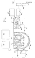
- Fig. 1 eine schematische Darstellung eines Siedewasser-Reaktors mit Druckabbausystem, der gemäß der Erfindung ausgestaltet ist
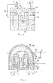
- Fig. 2 eine schematisihe Darstellung einer Druckwasser-Reaktor-Anlage mit einem Volldrucksicherheitsbehälter, der gemäß der Erfindung ausgerüstet ist, und
- Fig. 3 eine schematische Darstellung einer Druckwasser-Reaktor-Anlage mit Volldrucksicherheitsbehälter und sekundären Einrichtungen die für die Erfindung ausgerüstet ist.
- Fig. 1 is a schematic representation of a boiling water reactor with a pressure reduction system, which is designed according to the invention
- Fig. 2 is a schematic representation of a pressurized water reactor system with a full pressure safety container, which is equipped according to the invention, and
- Fig. 3 is a schematic representation of a pressurized water reactor system with full pressure containment and secondary facilities which is equipped for the invention.
Beide Reaktorsysteme Fig. 1 und 2 verfügen bislang nur über einen einzigen, ersten Sicherheitsbehälter, der jedoch durch weitere Systeme, insbesondere einen weiteren Sicherheitsbehälter und/oder spezielle Filtersysteme ergänzt werden kann, wie dies für zukünftige, alternative Konzepte diskutiert wird. Hierbei wurde bislang im wesentlichen die Verhinderung eines Überdruckversagens des eigentlichen (ersten) Sicherheitsbehälters betrachtet. Durch vergleichsweise geringfügige Änderungen bzw. Ergänzungen, die in Fig. 3 enthalten sind, kann das erfindungsgemäße Verfahren für alle Anlagen genutzt werden.Both reactor systems FIGS. 1 and 2 have so far only had a single, first safety container, which, however, can be supplemented by further systems, in particular a further safety container and / or special filter systems, as will be discussed for future, alternative concepts. So far, the prevention of overpressure failure of the actual (first) safety container has been considered. By means of comparatively minor changes or additions, which are contained in FIG. 3, the method according to the invention can be used for all systems.
Dies gilt nach Auffassung des Erfinders für das gesamte, mögliche Störfallspektrum, auch wenn aus Gründen der Beschränkung der Beschreibung auf ein vertretbares Maß, hier wiederum nur das Beispiel des weitgehend vollständiggiEsnschmelzens herausgegriffen wurde, da dies den mutmaßlich kritischsten Fall darstellt.In the inventor's opinion, this applies to the entire possible spectrum of accidents, even if, for reasons of restricting the description to an acceptable level, here again only the example of the largely complete melting was selected, since this represents the presumably most critical case.
Hinsichtlich technischer Einzelheiten von Kernkraftwerken und der bereits installierten oder vorgesehenen Sicherheitseinrichtungen, sowie Eintrittswahrscheinlichkeit, Ablauf und Folgen schwerer Störfälle ohne die Anwendung des erfindungsgemäßen Verfahren, wird auf die einschlägige Fachliteratur verwiesen (Sicherheitsberichte, Risikostudien von Kernkraftwerken usw.).With regard to the technical details of nuclear power plants and the safety devices already installed or planned, as well as the probability of occurrence, sequence and consequences of major accidents without using the method according to the invention, reference is made to the relevant specialist literature (safety reports, risk studies of nuclear power plants, etc.).
In einem Sicherheitsbehälter 5, der von einer Stahlbetonhülle 6 umgeben ist, befinden sichein Reaktordruckbehälter 1, der den Kernreaktor enthält, in dem gesteuert die für die Energieerzeugung erforderlichen Kernreaktionen ablaufen. In dem Sicherheitsbehälter 5 befinden sich ferner Druckspeicher 3 für ein Not- und Nachkühlsystem. Diese Druckspeicher 3 sind mit einem Not- und Nachkühlsystem 13 verbunden, welches auch die für die Steuerung dieses Systems erforderlichen Steuerungselemente aufweist. Ein Reaktorschnellabschaltsystem 4, welches nahe dem Reaktordruckbehälter 1 angeordnet ist, dient dazu, eine schnelle Abschaltung des Reaktors zu ermöglichen.In a
Schnellabschaltsysteme und Not- und Nachkühlsystemedienen bei sogenannten Auslegungsstörfällen dazu, die Anlage in einen sicheren Zustand überzuführen, ohne daß hierbei eine unerlaubte Strahlenbelastung der Umgebung eintritt. Versagen solche Systeme, so ist mit einer überhitzung des Kernes im Reaktordruckbehälter 1 und in der Folge mit größeren Mengen an Wasserstoff und Spaltprodukten im Sicherheitsbehälter 5 zu rechnen, als dies der Auslegung zugrundegelegt wurde. Im Falle des teilweisen oder vollständigen Kernschmelzens ist dann gleichzeitig ein Versagen des Sicherheitsbehälters 5 nicht auszuschließen. Das Kernschmelzen ist durch eine rasche und starke Wasserstoffbildung, insbesondere infolge sogenannter Metall-Wasser-Reaktionen und gleichzeitig aufgrund der hohen Temperaturen und der Zerstörung der sogenannten inneren Sicherheitsbarrieren (Brennstabhüllrohr, PrimärkühlmittelSystem) durch erhebliche Freisetzung von Spaltprodukten aus dem Brennstoff bzw. der Schmelze in die Atmosphäre des Sicherheitsbehälters 5 ausgezeichnet. Sicherheitsbehälter und Filtersysteme sowie Wasserstoffabbausysteme sind hierfür bislang nicht ausgelegt und zum Teil auch nicht derartigen Situationen anzupassen, so daß eine katastrophale Auswirkung auf Anlage und Umgebung nicht verhindert werden könnte. Durch Ertüchtigung und Anwendung der verschiedenen Maßnahmen des erfindungsgemäßen Verfahens kann dieser schwere Störfall weitgehend beherrscht oder zumindest eine Auswirkung auf die Umgebung drastisch reduziert werden.Rapid shutdown systems and emergency and after-cooling systems are used in so-called design accidents to bring the system into a safe state without causing an unauthorized radiation exposure to the environment. If such systems fail, an overheating of the core in the
Hierzu müssen zunächst Bereiche des primären d.h. des eigentlichen, ersten Sicherheitsbehälters 5 durch geeignete Vorrichtungen (z.B. steuerbare Klappen 43) bei Bedarf strömungstechnisch von einander getrennt werden können oder es muß ein zusätzlicher, sekundärer Behälter 14 angekoppelt werden können. Dieser kann in bekannter Weise als Volldruckbehälter oder als Druckabbausystem, wie in Fig. 3 beispielhaft durch das Druckabbausystem 14 dargestellt, ausgebildet sein. (Derartige Maßnahmen werden als sogenannte alternative Konzepte bereits diskutiert). In Abweichung zur bisherigen, bekannten Betrachtung soll dieser jedoch nunmehr nicht nur zur Beherrschung des anfallenden Überdruckes im primären Sicherheitsbehälter, sondern vor allem zur Trennung der reaktionsfähigen Komponenten Sauerstoff und insbesondere Wasserstoff dienen, indem eine Spülung des primären Sicherheitsbehälters mit inertem Gas und Trennung erfolgt, ehe große Mengen an vor allem Wasserstoff und Spaltprodukten in die Atmosphäre des primären Sicherheitsbehälters freigesetzt werden.For this, areas of the primary i.e. of the actual,
Ein Vorschlag für eine technische Ausgestaltung des erfindungsgemäßen Verfahrens bei Anwendung auf Leichtwasserreaktoren ist im folgenden beschrieben:
Außerhalb des Sicherheitsbehälters 5 befindet sichein Sekundarbehälter 14, der ein Druckabbausystem enthält.Der Sekundärbehälter 14weist eine Kammer 15 auf, die mit einerWasservorlage 16über Tauchrohre 17 in Strömungsverbindung steht.
- Outside the
safety container 5 there is asecondary container 14 which contains a pressure reduction system. Thesecondary container 14 has achamber 15 which is in flow connection with awater reservoir 16 viadip tubes 17.
Zwischen dem Inneren des Sicherheitsbehälters 5 und dem. Sekundärbehälter ist mindestens eine Verbindungsleitung 7 vorgesehen, die mit einem Ende in das Innere des Sicherheitsbehälters 5 und mit dem anderen Ende in die Kammer 15 mündet. In der Verbindungsleitung 7 ist mindestens ein Steuerventil 10 vorgesehen, durch welches der Durchfluß durch die Verbindungsleitung 7 wahlweise geöffnet oder gesperrt werden kann.Between the inside of the
Sowohl die Kammer 15 als auch der sich oberhalb der Wasservorlage befindende Raum 12 sind über z.B. Schieber 26 bzw. 27 strömungsmäßig mit einer Filterstrecke 19 verbunden, welche ihrerseits wiederum strömungsmäßig mit einem Abluftkamin 20 verbunden ist. Die Wasservorlage 16 kann über eine Verbindungsleitung 28 mit einer Abwasseraufbereitungsanlage 18 verbunden sein. In der Verbindungsleitung 28 ist ein z.B. Schieber 25 vorgesehen.Both the
Den Dampferzeugem2 wird über eine Verbindungsleitung 22 von nicht dargestellten Hauptspeisewasserpumpen Wasser zugeführt. Für den Fall,daß die Hauptspeisewasserpumpen nicht ausreichend arbeiten oder ihr Betrieb versagt, ist ein Notspeisewassersystem 11 vorgesehen, welches mit der Verbindungsleitung 22 verbunden wird um den Dampferzeugern 2 ausreichende Wassermengen zuführen zu können.The
Der von den Dampferzeugern 2 erzeugte Dampf wird über eine Verbindungsleitung 21 zu nicht dargestellten Tubinen geführt. In dieser Verbindungsleitung 21 ist ein Frischdampf-Schnellschlußschieber 8 vorgesehen, der dazu dient, die Frischdampfzufuhr zu den Turbinen zu unterbrechen, wenn dieses erforderlich ist. Über ein stromaufwärts des Frischdamof-Sdmellschlußschicbers 8 verbundenes Frischdampf-Sicherheitsventil 9 ist es möglich, durch Abführen von Frischdampf den Druck in den Dampferzeugern 2 zu verringern.The steam generated by the
Zur Durchführung des erfindungsgemäßen Verfahrens sind gemäß der gezeigten Darstellung Verbindungsleitungen 32 und 33 vorgesehen, welche von außerhalb des Sicherheitsbehälters 5 in dessen Inneres führen. Über Steuerventile 34 und 35 und eine Zuführleitung 31 sind die Verbindungsleitungen 32 und 33 mit einer Gasquelle 30 für ein Inertgas verbunden. Über das aus den Teilen 31 bis 35 bestehende Verbindungssystem kann Inertgas von der Gasquelle 30 in das Innere des Sicherheitsbehälters 5 eingebracht werden. Selbstverständlich können weitere, in den Sicherheitsbehälter führende Verbindungsleitungen und Steuerventile vorgesehen werden, wenn dieses erwünscht ist.To carry out the method according to the invention, connecting
Durch selektive Steuerung der Ventile 35 und 34 ist es möglich, diejenige Gasmenge zu steuern, die an verschiedenen Stellen innerhalb des Sicherheitsbehälters 5 eingebracht werden soll, wobei diese Stellen den Ausläßen der Verbindungsleitungen 32 und 33 entsprechen.By selectively controlling the
Aus Sicherheitsgründen ist es empfehlenswert, ein Noteinspeisungssystem 40 vorzusehen, welches über eine Verbindungsleitung 41 mit dem Inneren des Sicherheitsbehälters 5 verbünden ist. Beim Einsatz der Noteinspeisungseinrichtung strömt das Gas am Auslaß 42 der Verbindungsleitung 41 in den Sicherheitsbehälter 5.For safety reasons, it is advisable to provide an
Im folgenden wird dargestellt, auf welche Weise nach der Erfindung im Falle eines Kühlmittelverluststörfalles eine mögliche Gefährdung des Sicherheitsbehälters vermieden wird. Nach dem Auftreten eines Kühlmittelverluststörfalles werden die Steuerventile 10,34 und 35 geöffnet. Durch das Öffnen der Steaerventile 3h und 35 kann Inertgas aus der Inertgasquelle 30 über die Verbindungsleitungen 31, 32 und 33 in das Innere des Sicherheitsbehälters 5 gelangen.The following shows how the invention avoids a possible risk to the safety container in the event of a coolant loss accident. After the occurrence of a coolant loss accident, the
Grundsätzlich könnte als Inertgaseinspeisung auch Dampf aus dem Sekundärkreis eines Druckwasserreaktors entnommen und über Leitung 44 dem Inertgas-Einspeisesystem 30 zugeführt werden. Dadurch nimmt der Druck der Atmosphäre im Inneren des Sicherheitsbehälters zu, so daß sich in ihm befindende Atmosphäre über die Leitung 7 und das geöffnete Ventil 10 in die Kammer 15 des Sekundärbehälters gelangen kann. Die in den Sekundärbehälter 14 aus dem Inneren des Sicherheitsbehälters 5 überströmende Atmosphäre enthält nicht nur die ursprünglich im Sicherheitsbehälter vorhandene Luft, sondern auch im Zusammenhang mit dem Kühlmittelverluststörfall freigesetzten Wasserdampf und evtl. geringe Mengen Wasserstoff. Nach einem gewissen Zeitraum ist der Anteil der Luft im Inneren des Sicherheitsbehälters so gering geworden, daß keine Gefahr besteht, daß z.B. der nun rasch und in erheblichen Mengen freigesetzte Wasserstoff durch Zündquellen derart verbrennen kann, daß eine Gefährdung durch Verbrennung, Explosion, Quasi-Detonation oder Detonation hervorgerufen wird.In principle, steam could also be taken as an inert gas feed from the secondary circuit of a pressurized water reactor and fed to the inert
Verbrennt dennoch freigesetzter Wasserstoff mit dem noch im Sicherheitsbehälter enthaltenen Sauerstoff, wodurch eine Druckverringerung der Atmosphäre innerhalb des Sicherheitsbehälters erfolgt, so kann dies erforderlichenfalls durch weiteres Einströmen von Inertgas ausgeglichen werden. Dabei ist es zu diesem Zeitpunkt des Ablaufes des Störfalles von Vorteil, wenn der Druck der Atmosphäre innerhalb des Sicherheitsbehälters 5 auf einem Wert gehalten wird, der unter dem Wert liegt, den die den Sicherheitsbehälter 5 umgebende Atmosphäre aufweist. Hierzu kann die vorzeitige oder nachträgliche Schließung des Steuerventiles 10 oder eine Drosselung oder die Ausbildung als Einwegventil sowie vor Verbrennung evtl. die Erhöhung des Druckes im äußeren sogenannten Ringraum 46erforderlich sein. Durch den innerhalb des Sicherheitsbehälters 5 vorliegenden relativen Unterdruck wird erreicht, daß keine verseuchte Atmosphäre nach außen gelangen kann, sondern Leckagen nach innen gerichtet sind.However, if the released hydrogen burns with the oxygen still contained in the containment, thereby reducing the pressure in the atmosphere inside the containment, this can be compensated for if necessary by further inflow of inert gas. It is advantageous at this point in time for the accident to occur if the pressure of the atmosphere inside the
Aus der zu Beginn des Störfalles oder während der Langzeitphase, z.B. aufgrund der aus 46 nach innen gerichteten Leckage des primären Sicherheitsbehälters 5, in den Sekundärbehälter 14 gelangenden Atmosphäre wird der Wasserdampf durch die Wasservorlage 16 auskondensiert und zu einem erwünschten Zeitpunkt der Abwasseraufbereitungseinrichtung 18 zugeführt. Die im gasförmigen Zustand verbleibende Atmosphäre kann nach einem Zeitraum, dessen Länge von der Stärke der Radioaktivität dieser Atmosphäre abhängt, über eine Reinigungsfilterstrecke 19, der ein Abluftkamin 20 nachgeschaltet ist, an die Atmosphäre abgegeben werden.From the beginning of the accident or during the long-term phase, e.g. due to the inward leakage of the
In besonderen Fällen, z.B. wenn in einer Anfangsphase aufgrund analytischer Erkenntnisse (Mess.ng, Simulation) noch ein niedriger Schadstoffgehalt (hier Spaltprodukte) vorliegt, jedoch eine spätere besonders ungünstige Situation erwartet werden muß, oder Schäden am sekundären Sicherheitsbehälter erkennbar sind, kann es entgegen bestehender Auffassung erfindungsgemäß von Vorteil sein, bereits frühzeitig eine Abgabe von Atmosphäre über Filter 19 und Kamin 20 vorzunehmen.In special cases, e.g. If, in an initial phase, due to analytical findings (measurement, simulation,) there is still a low pollutant content (here fission products), but a later particularly unfavorable situation must be expected, or if damage to the secondary containment can be identified, it may be advantageous according to the invention, contrary to the existing view be to release the atmosphere at an early stage via
Grundsätzlich können die erfindungsgemäßen Vorteile auch im Falle von Altanlagen ohne Ergänzung durch zusätzliche Sicherheitsbehälter und Filterstrecken, also unter Nutzung bereits vorhandener Einrichtungen, wie primärer Sicherheitsbehälter und normale Störfallfilter, genutzt werden, wenn diese durch Absperreinrichtungen 43 ergänzt werden, so daß z.B. die Funktion eines sekundären Sicherheitsbehälters durch einen absperrbaren Bereich 47 des primären Sicherheitsbehälters 5 übernommen wird. Hierbei könnte das Auskondensieren von in den sekundären Bereich 47 gelangendem Dampfes beispielsweise durch Außenkühlung des Sicherheitsbehälters beim Druckwasserreaktor (Fig.2) oder Spraysysteme im Inneren bewirkt werden. Diese strömungstechnisch gerichtet und/oder steuerbar zu trennenden Bereiche sind beim Volldruckbehälter eines Druckwasserreaktors (Fig.2) vorzugsweise der Bereich der Anlageräume 48 einerseits und der Bereich der Betriebsräume 47 andererseits, die z.B. durch Überströmklappen 43 an den oberen Enden der Dampferzeugertürme getrennt werden. Beim Druckabbausystem wie es derart für Siedewasserreaktoren verwirklicht ist (Fig.1) sind dies(nach Ertüchtigung) die Bereiche Druckkammer 48 und Kondensationskammer 47.In principle, the advantages according to the invention can also be used in the case of old systems without the addition of additional safety containers and filter sections, that is to say using existing facilities such as primary safety containers and normal accident filters, if these are supplemented by shut-off
Es ist auch denkbar im Sinne eines gestaffelten System sowohl die Ergänzungen im primären Sicherheitsbehälter als auch die Erweiterung durch Ankopplung eines sekundären Sicherheitsbehälters vorzunehmen.In the sense of a staggered system, it is also conceivable to carry out both the additions in the primary containment and the expansion by coupling a secondary containment.
Die Realisation des zweiten Sicherheitsbehälters in Form eines Druckabbausystems hat neben zu erwartenden kostenmäßigen Vorzügen die Vorteile, daß hierbei sowohl ein zeitlich nahezu unbegrenztes Spülen des primären Sicherheitsbehälters mit Dampf ermöglicht wird, als auch gleichzeitig die Wasservorlage als kondensierender Gaswäscher genutzt werden kann, wodurch sowohl hinsichtlich der Druckreglung in beiden Sicherheitsbehältern als auch für die Beaufschlagung von Spaltproduktfiltern besonders günstige Voraussetzungen geschaffen werden.The realization of the second safety container in the form of a pressure reduction system has the expected cost advantages as well as the fact that this enables both an almost unlimited flushing of the primary safety container with steam, and at the same time the water reserve can be used as a condensing gas scrubber, which means both in terms of Pressure regulation in both safety containers and for the application of fission product filters, particularly favorable conditions are created.
Claims (24)
Priority Applications (7)
| Application Number | Priority Date | Filing Date | Title |
|---|---|---|---|
| DE8181100534T DE3177046D1 (en) | 1981-01-25 | 1981-01-25 | Hazard avoiding or diminishing method for an installation and its environment due to reacting mixtures |
| EP81100534A EP0056830B2 (en) | 1981-01-25 | 1981-01-25 | Hazard avoiding or diminishing method for an installation and its environment due to reacting mixtures |
| AT81100534T ATE42651T1 (en) | 1981-01-25 | 1981-01-25 | PROCEDURES TO PREVENT OR REDUCE THE RISK OF REACTING MIXTURES ON PLANT AND SURROUNDINGS. |
| FI820185A FI820185A7 (en) | 1981-01-25 | 1982-01-21 | Method for avoiding or reducing exposure of equipment and its environment to hazards from reactive mixtures. |
| JP57009921A JPS57156591A (en) | 1981-01-25 | 1982-01-25 | Method of decreasing or protecting danger against reactive mixture system and its circumference |
| CA000394831A CA1188432A (en) | 1981-01-25 | 1982-01-25 | Process for precluding or reducing the danger to a system during an accident |
| US06/756,816 US4797249A (en) | 1981-01-25 | 1985-07-18 | Process for precluding or reducing the danger to a system and the surroundings thereof by reactive mixtures |
Applications Claiming Priority (1)
| Application Number | Priority Date | Filing Date | Title |
|---|---|---|---|
| EP81100534A EP0056830B2 (en) | 1981-01-25 | 1981-01-25 | Hazard avoiding or diminishing method for an installation and its environment due to reacting mixtures |
Publications (3)
| Publication Number | Publication Date |
|---|---|
| EP0056830A1 true EP0056830A1 (en) | 1982-08-04 |
| EP0056830B1 EP0056830B1 (en) | 1989-04-26 |
| EP0056830B2 EP0056830B2 (en) | 1993-12-15 |
Family
ID=8187548
Family Applications (1)
| Application Number | Title | Priority Date | Filing Date |
|---|---|---|---|
| EP81100534A Expired - Lifetime EP0056830B2 (en) | 1981-01-25 | 1981-01-25 | Hazard avoiding or diminishing method for an installation and its environment due to reacting mixtures |
Country Status (7)
| Country | Link |
|---|---|
| US (1) | US4797249A (en) |
| EP (1) | EP0056830B2 (en) |
| JP (1) | JPS57156591A (en) |
| AT (1) | ATE42651T1 (en) |
| CA (1) | CA1188432A (en) |
| DE (1) | DE3177046D1 (en) |
| FI (1) | FI820185A7 (en) |
Cited By (6)
| Publication number | Priority date | Publication date | Assignee | Title |
|---|---|---|---|---|
| EP0070037A3 (en) * | 1981-07-14 | 1984-02-08 | Hermann Dr. Jahn | Process for preventing or checking the blending of the atmosphere existent in a confined space with a gaseous material present in that space |
| EP0263993A3 (en) * | 1986-10-17 | 1988-07-20 | Kernforschungszentrum Karlsruhe Gmbh | Pressure suppression system for a security confinement of a nuclear reactor |
| EP0285845A1 (en) * | 1987-03-23 | 1988-10-12 | Siemens Aktiengesellschaft | Method and device for pressure suppression of a nuclear power plant |
| EP0290028A1 (en) * | 1987-05-08 | 1988-11-09 | Siemens Aktiengesellschaft | Pressure release apparatus and filter assembly for nuclear installations, particularly for pressurized-water reactors |
| DE3927958A1 (en) * | 1988-09-17 | 1990-03-22 | Gemeinschaftskernkraftwerk Nec | METHOD FOR PREVENTING HAZARDS IN INTERFERING WATER-COOLED CORE REACTORS AND DEVICE THEREFOR |
| EP0466052A1 (en) * | 1990-07-06 | 1992-01-15 | Hermann Dr. Jahn | Method for reducing accident hazards |
Families Citing this family (6)
| Publication number | Priority date | Publication date | Assignee | Title |
|---|---|---|---|---|
| DE59300973D1 (en) * | 1993-08-24 | 1995-12-21 | Anlagen Und Reaktorsicherheit | Device for passive inertization of the gas mixture in the safety container of a nuclear power plant. |
| US6262328B1 (en) | 1999-06-11 | 2001-07-17 | Westinghouse Savannah River Company | Container and method for absorbing and reducing hydrogen concentration |
| JP5006178B2 (en) * | 2007-12-21 | 2012-08-22 | 株式会社東芝 | Reactor containment vessel and nuclear power plant using the same |
| US9502144B2 (en) * | 2012-07-06 | 2016-11-22 | Westinghouse Electric Company Llc | Filter for a nuclear reactor containment ventilation system |
| JP5898018B2 (en) * | 2012-08-27 | 2016-04-06 | 日立Geニュークリア・エナジー株式会社 | Containment Vessel Filter Vent Device and Reactor Containment Vessel |
| BR112019006253B1 (en) * | 2016-11-28 | 2022-10-04 | Framatome Gmbh | NUCLEAR POWER INSTALLATION COMPRISING A CONTAINMENT AND A CONTAINMENT VENTILATION SYSTEM |
Citations (8)
| Publication number | Priority date | Publication date | Assignee | Title |
|---|---|---|---|---|
| GB862624A (en) * | 1958-07-09 | 1961-03-15 | Atomic Energy Authority Uk | Improvements in or relating to nuclear reactor installations |
| US3115450A (en) * | 1959-02-24 | 1963-12-24 | Gen Electric | Nuclear reactor containment apparatus |
| US3307913A (en) * | 1962-07-27 | 1967-03-07 | Stone & Webster Eng Corp | Vacuum producing apparatus for containment vessels |
| FR2042604A1 (en) * | 1969-05-13 | 1971-02-12 | Babcock & Wilcox Co | |
| DE2115264A1 (en) * | 1971-03-30 | 1972-10-05 | Kernforschung Gmbh Ges Fuer | Pressure reducing containment - for liquid sodium reactor plants |
| US3865688A (en) * | 1970-08-05 | 1975-02-11 | Frank W Kleimola | Passive containment system |
| DE2805476A1 (en) * | 1978-02-09 | 1979-08-23 | Hermann Dipl Ing Jahn | Gas concentrations in stratified atmosphere - are broken down by adding gas to one or more layers to change density at interface |
| US4210614A (en) * | 1970-08-05 | 1980-07-01 | Nucledyne Engineering Corp. | Passive containment system |
Family Cites Families (5)
| Publication number | Priority date | Publication date | Assignee | Title |
|---|---|---|---|---|
| GB1092536A (en) * | 1964-05-25 | 1967-11-29 | Atomic Energy Authority Uk | Improvements in or relating to nuclear reactors |
| JPS424640Y1 (en) * | 1964-11-07 | 1967-03-11 | ||
| US3889707A (en) * | 1971-11-19 | 1975-06-17 | Gen Atomic Co | Pressure relief system for a nuclear reactor |
| DE2633113C2 (en) * | 1976-07-23 | 1984-08-30 | Kernforschungszentrum Karlsruhe Gmbh, 7500 Karlsruhe | Procedure for avoiding hazards arising from accidents on water-cooled nuclear reactors |
| DE3127804A1 (en) * | 1981-07-14 | 1983-02-10 | Schweiger, W., Dr.-Ing., 8039 Puchheim | METHOD FOR PREVENTING OR INHIBITING A MIXING OF THE ATMOSPHERES EXISTING IN A CLOSED ROOM WITH A GAS-LIKE MATERIAL IN THE ROOM |
-
1981
- 1981-01-25 DE DE8181100534T patent/DE3177046D1/en not_active Expired
- 1981-01-25 EP EP81100534A patent/EP0056830B2/en not_active Expired - Lifetime
- 1981-01-25 AT AT81100534T patent/ATE42651T1/en not_active IP Right Cessation
-
1982
- 1982-01-21 FI FI820185A patent/FI820185A7/en not_active Application Discontinuation
- 1982-01-25 CA CA000394831A patent/CA1188432A/en not_active Expired
- 1982-01-25 JP JP57009921A patent/JPS57156591A/en active Pending
-
1985
- 1985-07-18 US US06/756,816 patent/US4797249A/en not_active Expired - Lifetime
Patent Citations (8)
| Publication number | Priority date | Publication date | Assignee | Title |
|---|---|---|---|---|
| GB862624A (en) * | 1958-07-09 | 1961-03-15 | Atomic Energy Authority Uk | Improvements in or relating to nuclear reactor installations |
| US3115450A (en) * | 1959-02-24 | 1963-12-24 | Gen Electric | Nuclear reactor containment apparatus |
| US3307913A (en) * | 1962-07-27 | 1967-03-07 | Stone & Webster Eng Corp | Vacuum producing apparatus for containment vessels |
| FR2042604A1 (en) * | 1969-05-13 | 1971-02-12 | Babcock & Wilcox Co | |
| US3865688A (en) * | 1970-08-05 | 1975-02-11 | Frank W Kleimola | Passive containment system |
| US4210614A (en) * | 1970-08-05 | 1980-07-01 | Nucledyne Engineering Corp. | Passive containment system |
| DE2115264A1 (en) * | 1971-03-30 | 1972-10-05 | Kernforschung Gmbh Ges Fuer | Pressure reducing containment - for liquid sodium reactor plants |
| DE2805476A1 (en) * | 1978-02-09 | 1979-08-23 | Hermann Dipl Ing Jahn | Gas concentrations in stratified atmosphere - are broken down by adding gas to one or more layers to change density at interface |
Non-Patent Citations (1)
| Title |
|---|
| Nuclear Safety, Band 15, Nr. 2, Marz/April 1974 G.E. Wade: "Evolution and Current Status of the BWR Containment System", seiten 163-173. *seite 171 "Hydrogen Control Systems"; Figur 6* * |
Cited By (8)
| Publication number | Priority date | Publication date | Assignee | Title |
|---|---|---|---|---|
| EP0070037A3 (en) * | 1981-07-14 | 1984-02-08 | Hermann Dr. Jahn | Process for preventing or checking the blending of the atmosphere existent in a confined space with a gaseous material present in that space |
| EP0263993A3 (en) * | 1986-10-17 | 1988-07-20 | Kernforschungszentrum Karlsruhe Gmbh | Pressure suppression system for a security confinement of a nuclear reactor |
| EP0285845A1 (en) * | 1987-03-23 | 1988-10-12 | Siemens Aktiengesellschaft | Method and device for pressure suppression of a nuclear power plant |
| US4873050A (en) * | 1987-03-23 | 1989-10-10 | Siemens Aktiengesellschaft | Method and apparatus for pressure relief of a nuclear power plant |
| EP0290028A1 (en) * | 1987-05-08 | 1988-11-09 | Siemens Aktiengesellschaft | Pressure release apparatus and filter assembly for nuclear installations, particularly for pressurized-water reactors |
| WO1988009039A1 (en) * | 1987-05-08 | 1988-11-17 | Siemens Aktiengesellschaft | Pressure-relief and filter device for pressurized water reactors |
| DE3927958A1 (en) * | 1988-09-17 | 1990-03-22 | Gemeinschaftskernkraftwerk Nec | METHOD FOR PREVENTING HAZARDS IN INTERFERING WATER-COOLED CORE REACTORS AND DEVICE THEREFOR |
| EP0466052A1 (en) * | 1990-07-06 | 1992-01-15 | Hermann Dr. Jahn | Method for reducing accident hazards |
Also Published As
| Publication number | Publication date |
|---|---|
| ATE42651T1 (en) | 1989-05-15 |
| FI820185L (en) | 1982-07-26 |
| JPS57156591A (en) | 1982-09-27 |
| FI820185A7 (en) | 1982-07-26 |
| CA1188432A (en) | 1985-06-04 |
| EP0056830B2 (en) | 1993-12-15 |
| US4797249A (en) | 1989-01-10 |
| DE3177046D1 (en) | 1989-06-01 |
| EP0056830B1 (en) | 1989-04-26 |
Similar Documents
| Publication | Publication Date | Title |
|---|---|---|
| DE3435255C2 (en) | ||
| DE102012211897B3 (en) | Nuclear plant e.g. boiling-water reactor type nuclear power plant, for producing current, has flow channel, where mixture flows into channel according to forced flow principle, and disperses above discharge line as pressure discharge flow | |
| EP0056830B2 (en) | Hazard avoiding or diminishing method for an installation and its environment due to reacting mixtures | |
| DE2241303C3 (en) | Arrangement for pressure-reducing decontamination spray for a nuclear reactor plant | |
| DE69010977T2 (en) | Indirect passive cooling system for nuclear reactors with liquid metal cooling. | |
| DE102006010826A1 (en) | Nuclear facility and closure device for their containment | |
| DE3212265C2 (en) | Process and device for the targeted derivation of activity from the reactor protection building of a gas-cooled nuclear power plant | |
| DE2441999A1 (en) | PROCEDURE FOR CONTINUOUS INSPECTION OF THE DOUBLE-SHELL REACTOR VESSEL OF A REACTOR AND REACTOR FOR USING THIS PROCEDURE | |
| DE1957701A1 (en) | Control system for nuclear reactors | |
| EP1233423B1 (en) | Apparatus for cooling and protecting a reactor pressure vessel in the event of a core melting accident | |
| DE2516123B2 (en) | Process for removing the heat of decay from radioactive fission products | |
| EP0466052B1 (en) | Method for reducing accident hazards | |
| EP0070037A2 (en) | Process for preventing or checking the blending of the atmosphere existent in a confined space with a gaseous material present in that space | |
| EP1497835B2 (en) | Intermediate storage system for fuel elements from a nuclear facility, and method for operating one such intermediate storage system | |
| DE2519273C3 (en) | Process for the thermal protection of the ceiling reflector of a high-temperature reactor | |
| DE3446141A1 (en) | IN A STEEL PRESSURE CONTAINED CORE REACTOR SYSTEM WITH A GAS-COOLED HT SMALL REACTOR | |
| DE3335268C2 (en) | ||
| DE1105531B (en) | Nuclear reactor moderated by graphite with a positive temperature coefficient of the moderator influence on reactivity | |
| DE2805476C3 (en) | Method for resolving local gas concentrations in superimposed atmospheres | |
| WO1996020486A1 (en) | Emergency cooling arrangement for a nuclear reactor plant and process for the emergency cooling of a reactor core | |
| DE3212322A1 (en) | Method for controlling design basis and hypothetical accidents in a nuclear power station | |
| DE2430725C3 (en) | Overpressure relief for a nuclear reactor facility | |
| DE2129169A1 (en) | Nuclear reactor | |
| DE2945964C2 (en) | ||
| DE2154831C3 (en) | Device for supporting the moderator structure of a nuclear reactor |
Legal Events
| Date | Code | Title | Description |
|---|---|---|---|
| PUAI | Public reference made under article 153(3) epc to a published international application that has entered the european phase |
Free format text: ORIGINAL CODE: 0009012 |
|
| AK | Designated contracting states |
Designated state(s): AT BE CH DE FR GB IT LU NL SE |
|
| 17P | Request for examination filed |
Effective date: 19830204 |
|
| RAP1 | Party data changed (applicant data changed or rights of an application transferred) |
Owner name: JAHN, HERMANN, DR. |
|
| RIN1 | Information on inventor provided before grant (corrected) |
Inventor name: SCHWEIGER, WILLY, DR.-ING. |
|
| GRAA | (expected) grant |
Free format text: ORIGINAL CODE: 0009210 |
|
| AK | Designated contracting states |
Kind code of ref document: B1 Designated state(s): AT BE CH DE FR GB IT LI LU NL SE |
|
| PG25 | Lapsed in a contracting state [announced via postgrant information from national office to epo] |
Ref country code: SE Effective date: 19890426 Ref country code: NL Effective date: 19890426 Ref country code: IT Free format text: LAPSE BECAUSE OF FAILURE TO SUBMIT A TRANSLATION OF THE DESCRIPTION OR TO PAY THE FEE WITHIN THE PRESCRIBED TIME-LIMIT;WARNING: LAPSES OF ITALIAN PATENTS WITH EFFECTIVE DATE BEFORE 2007 MAY HAVE OCCURRED AT ANY TIME BEFORE 2007. THE CORRECT EFFECTIVE DATE MAY BE DIFFERENT FROM THE ONE RECORDED. Effective date: 19890426 |
|
| REF | Corresponds to: |
Ref document number: 42651 Country of ref document: AT Date of ref document: 19890515 Kind code of ref document: T |
|
| GBT | Gb: translation of ep patent filed (gb section 77(6)(a)/1977) | ||
| REF | Corresponds to: |
Ref document number: 3177046 Country of ref document: DE Date of ref document: 19890601 |
|
| ET | Fr: translation filed | ||
| NLV1 | Nl: lapsed or annulled due to failure to fulfill the requirements of art. 29p and 29m of the patents act | ||
| PGFP | Annual fee paid to national office [announced via postgrant information from national office to epo] |
Ref country code: GB Payment date: 19891231 Year of fee payment: 10 |
|
| PGFP | Annual fee paid to national office [announced via postgrant information from national office to epo] |
Ref country code: BE Payment date: 19900111 Year of fee payment: 10 |
|
| PG25 | Lapsed in a contracting state [announced via postgrant information from national office to epo] |
Ref country code: AT Effective date: 19900125 |
|
| PLBI | Opposition filed |
Free format text: ORIGINAL CODE: 0009260 |
|
| PG25 | Lapsed in a contracting state [announced via postgrant information from national office to epo] |
Ref country code: LU Free format text: LAPSE BECAUSE OF NON-PAYMENT OF DUE FEES Effective date: 19900131 |
|
| PGFP | Annual fee paid to national office [announced via postgrant information from national office to epo] |
Ref country code: CH Payment date: 19900206 Year of fee payment: 10 |
|
| 26 | Opposition filed |
Opponent name: SIEMENS AKTIENGESELLSCHAFT, BERLIN UND MUENCHEN Effective date: 19900123 |
|
| PG25 | Lapsed in a contracting state [announced via postgrant information from national office to epo] |
Ref country code: GB Effective date: 19910125 |
|
| PG25 | Lapsed in a contracting state [announced via postgrant information from national office to epo] |
Ref country code: LI Effective date: 19910131 Ref country code: CH Effective date: 19910131 Ref country code: BE Effective date: 19910131 |
|
| GBPC | Gb: european patent ceased through non-payment of renewal fee | ||
| REG | Reference to a national code |
Ref country code: CH Ref legal event code: PL |
|
| PUAH | Patent maintained in amended form |
Free format text: ORIGINAL CODE: 0009272 |
|
| STAA | Information on the status of an ep patent application or granted ep patent |
Free format text: STATUS: PATENT MAINTAINED AS AMENDED |
|
| 27A | Patent maintained in amended form |
Effective date: 19931215 |
|
| AK | Designated contracting states |
Kind code of ref document: B2 Designated state(s): AT BE CH DE FR GB IT LI LU NL SE |
|
| ET3 | Fr: translation filed ** decision concerning opposition | ||
| PGFP | Annual fee paid to national office [announced via postgrant information from national office to epo] |
Ref country code: FR Payment date: 19990118 Year of fee payment: 19 |
|
| PGFP | Annual fee paid to national office [announced via postgrant information from national office to epo] |
Ref country code: DE Payment date: 19990311 Year of fee payment: 19 |
|
| PG25 | Lapsed in a contracting state [announced via postgrant information from national office to epo] |
Ref country code: FR Free format text: LAPSE BECAUSE OF NON-PAYMENT OF DUE FEES Effective date: 20000929 |
|
| PG25 | Lapsed in a contracting state [announced via postgrant information from national office to epo] |
Ref country code: DE Free format text: LAPSE BECAUSE OF NON-PAYMENT OF DUE FEES Effective date: 20001101 |
|
| REG | Reference to a national code |
Ref country code: FR Ref legal event code: ST |
|
| APAH | Appeal reference modified |
Free format text: ORIGINAL CODE: EPIDOSCREFNO |