EP0056483B2 - Vorrichtung für ein elktrisches Querstromgebläse - Google Patents
Vorrichtung für ein elktrisches Querstromgebläse Download PDFInfo
- Publication number
- EP0056483B2 EP0056483B2 EP81110705A EP81110705A EP0056483B2 EP 0056483 B2 EP0056483 B2 EP 0056483B2 EP 81110705 A EP81110705 A EP 81110705A EP 81110705 A EP81110705 A EP 81110705A EP 0056483 B2 EP0056483 B2 EP 0056483B2
- Authority
- EP
- European Patent Office
- Prior art keywords
- flow
- air
- pivotable plate
- vortex
- fan
- Prior art date
- Legal status (The legal status is an assumption and is not a legal conclusion. Google has not performed a legal analysis and makes no representation as to the accuracy of the status listed.)
- Expired
Links
Images
Classifications
-
- F—MECHANICAL ENGINEERING; LIGHTING; HEATING; WEAPONS; BLASTING
- F04—POSITIVE - DISPLACEMENT MACHINES FOR LIQUIDS; PUMPS FOR LIQUIDS OR ELASTIC FLUIDS
- F04D—NON-POSITIVE-DISPLACEMENT PUMPS
- F04D17/00—Radial-flow pumps, e.g. centrifugal pumps; Helico-centrifugal pumps
- F04D17/02—Radial-flow pumps, e.g. centrifugal pumps; Helico-centrifugal pumps having non-centrifugal stages, e.g. centripetal
- F04D17/04—Radial-flow pumps, e.g. centrifugal pumps; Helico-centrifugal pumps having non-centrifugal stages, e.g. centripetal of transverse-flow type
Definitions
- the present invention relates to an electric fan assembly comprising a generally cylindrical cross-flow fan rotatable about a fan axle to produce a vortex of air thereby to produce a flow of air, a stabilizer and a rear guider, disposed on opposite sides of said fan axle, said rear guider having an upstream wall with respect to the direction of flow of the air and which is fixed relative to the fan axle.
- Such an assembly is known from US-A-3 249 292 which refers to a cross-flow fluid machine comprising a cylindrical bladed rotor mounted for rotation about its axis through which upon rotation of the rotor a vortex of air passes through the path of the rotating blades in the direction transverse to the axis of the rotor to produce a flow of air current. Furthermore, end walls are provided for substantially including the ends of the rotor and guide walls extending the length of the rotor and forming a side wall of an exit duct.
- a vortex forming and stabilizing means is established for forming a substantially cylindrically shaped vortex when the machine is operated extending the length of the rotor so that the air is made to flow from a suction side of the machine into the rotor through the path of the rotating blades and then out of the rotor through the path of the rotating blades to the exit duct in a plane transverse to the rotor axis.
- the position of the vortex core with respect to the outlet walls of the cross-flow fluid machine may be changed for regulating the air current throughput of the cross-flow machine, whereby the vortex can be made smaller or larger resulting in a greater or less throughput of the machine.
- the vortex moves in an axial direction and only a small-angle deflection of the air stream can be obtained with respect to the movement of the vortex forming and stabilizing means.
- the pivotable vortex forming and stabilizing means only serves for changing the throughput of the machine.
- the electric cross-flow fan assembly is characterized in that a pivotable plate is hingedly connected with its upstream edge to the downstream edge of the rear guider, said pivotable plate being so designed that the air flow can adhere thereto and being so pivotably adjustable as to adjust the position of the vortex.
- the pivotable plate is so shaped that the air current can readily adhere thereto, whereby it is made of a substantial flat plate shape.
- the angle of edge of the stabilizer is selected to be small enough to facilitate the shift of the vortex in the tangential direction.
- the pivotable plate is pivotable about the shaft and is arranged downstream of the rear guider so that the air flow can adhere to the pivotable plate and a wide-angle deflection of the air stream can be obtained or, by causing the vortex to be moved largely, the direction of air flow can be widely changed.
- the tangential shifting direction of the vortex by means of a special shaped stabilizer in combination with the pivotable plate which is arranged in structure such that the air current can adhere thereto, allows an easy and effective regulation of the air flow and a real compact size of the whole fan assembly for use in a domestic heating and/or cooling device.
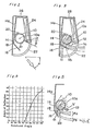
- the fan assembly comprises a generally cylindrical cross-flow fan 10 rotatable about a fan axle 10a and effective to produce a vortex V of air thereby to produce the flow of air current during the rotation thereof about the fan axle 10a, a stabilizer 12 for stabilizing the vortex, a rear guider 14 having an upstream edge portion 14a, with respect to the direction of flow of the air current and a pivotable plate 16 having its upstream edge hingedly connected at 18 to a downstream edge of the rear guider 14.
- the rear guider 14 has a regulating plate 20 for regulating the direction in which air is sucked and also for stabilizing the vortex when the latter is moved, i.e., shifted in position.
- the stabilizer 12 has a relatively small angle of wedge, shown by 0, for the purpose of facilitating the shift in position of the vortex.
- the excessively small angle of wedge 0 tends to result in a reduced volume of air flow.
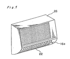
- Reference numeral 26 represents a generally rectangular casing for a wall-mount indoor unit of a split system heat pump having a louver 22 for deflecting the air current in a laterial direction, i.e., selectively leftwards and rightwards and a heat exchanger 24 positioned on the upstream side of the fan assembly with respect to the direction of flow of air towards the fan 10.
- the pivotable plate 16 has a manipulatable lever 16a extending therefrom and exposed to the outside of the casing 26 at a position laterally of the louver 22 so that, by moving the lever 16a, the position of the pivotable plate 16 relative to the fan 10 can be adjusted.
- the rotation of the cross-flow fan 10 is accompanied by the occurrence of the vortex Va at a region adjacent the stabilizer 12.
- the air flows in a manner as shown by the arrow- headed solid lines in a substantially horizontal direction.
- the regulating plate 20 may facilitate the stabilization of the vortex Vb by regulating the direction in which the air is sucked. However, this may not be always necessary.
- Fig. 4 illustrates the relationship between the angle 0 1 , of rotation of the pivotable plate 16 and the angle a of deflection, and it will readily be seen that the angle a starts increasing when the angle 0 1 , of rotation of the pivotable plate 16 is 45° and attains 90° when the angle 8, of rotation of the pivotable plate 16 is 90°. That is to say, the rotation of the pivotable plate 16 through the angle 0 1 , results in deflection in an angle a which is twice the angle ⁇ 1 . In view of this, a slight movement of the manipulatable lever 16a is sufficient to bring about the deflection through the two-fold angle.
- the pivotable plate 16 may be made to be rotated by a motor for the purpose of achieving an automatic deflection. Even in this case, a quick control can be achieved because the relatively small angle 8, of rotation of the pivotable plate 16 can give the relatively large angle of deflection. Moreover, since the control can be performed only by the rotation about the upstream edge 18, the design is simple and the casing can have a reduced thickness.
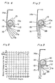
- the fan assembly of the construction shown particularly in Figs. 2 and 3 is satisfactory, it may have a flow control member for controlling the air current without adversely affecting the rate of flow thereof even when the direction of blow of the air current is changed. This will now be described with reference to Figs. 5 to 7.
- the flow control member is identified by 28 and is positioned adjacent the fan 10 at a downstream side with respect to the direction of flow of the air current and between the stabilizer 12 and the pivotable plate 16.
- This flow control member 28 is operable to divide the air current, produced by the occurrence of the vortex V in the manner as hereinbefore described, into two flow components and to facilitate the adherence of one of the flow components, which flows adjacent the pivotable plate 16, to the pivotable plate 16, thereby to shift the position of the vortex V in a direction close towards the pivotable plate 16 and then lock it thereat.
- the flow control member 28 so far shown is in the form of a cylindrical rod because of its simple construction and also because of the availability of its assured function, but it may be of any other shape.
- the air current produced by the occurrence of the vortex V in the manner as hereinbefore described in connection with the foregoing embodiment is divided into two current components Fa and Fb by the flow control member 28.
- the current component Fa flowing past a region between the flow control member 28 and the stabilizer 12 tends to travel in the horizontal direction by the action of the vortex V.
- the vortex V shifts in position towards the pivotable plate 16 and, at the same time, the quantity of the current component Fb which adheres to the pivotable plate 16 increases gradually.
- the quantity of the current component Fb becomes of a value which cannot be neglected relative to the quantity of the current component Fa, and the two current components Fa and Fb interfere with each other, resulting in that the air current as a whole flows in the direction in which the two current components join together.
- the vortex V is, at this time, positioned at a region spaced from the stabilizer a distance larger than that shown in Fig. 5 and is stabilized thereat by the action of the current component Fb which has adhered to the pivotable plate 16 by the action of the flow control member 28.
- the flow control member 28 may be made movable and this will be described with reference to Fig. 9.
Landscapes
- Engineering & Computer Science (AREA)
- Mechanical Engineering (AREA)
- General Engineering & Computer Science (AREA)
- Structures Of Non-Positive Displacement Pumps (AREA)
- Air-Conditioning Room Units, And Self-Contained Units In General (AREA)
Claims (5)
Applications Claiming Priority (6)
| Application Number | Priority Date | Filing Date | Title |
|---|---|---|---|
| JP55186423A JPS57108495A (en) | 1980-12-25 | 1980-12-25 | Blower device |
| JP186423/80 | 1980-12-25 | ||
| JP14794/81 | 1981-02-02 | ||
| JP56014794A JPS57129295A (en) | 1981-02-02 | 1981-02-02 | Arrangement for fan |
| JP56057365A JPS57171096A (en) | 1981-04-15 | 1981-04-15 | Ventilator |
| JP57365/81 | 1981-04-15 |
Publications (3)
| Publication Number | Publication Date |
|---|---|
| EP0056483A1 EP0056483A1 (de) | 1982-07-28 |
| EP0056483B1 EP0056483B1 (de) | 1985-10-09 |
| EP0056483B2 true EP0056483B2 (de) | 1989-09-13 |
Family
ID=27280765
Family Applications (1)
| Application Number | Title | Priority Date | Filing Date |
|---|---|---|---|
| EP81110705A Expired EP0056483B2 (de) | 1980-12-25 | 1981-12-23 | Vorrichtung für ein elktrisches Querstromgebläse |
Country Status (5)
| Country | Link |
|---|---|
| US (1) | US4462750A (de) |
| EP (1) | EP0056483B2 (de) |
| AU (1) | AU547656B2 (de) |
| CA (1) | CA1207724A (de) |
| DE (1) | DE3172642D1 (de) |
Families Citing this family (7)
| Publication number | Priority date | Publication date | Assignee | Title |
|---|---|---|---|---|
| US4913622A (en) * | 1987-01-30 | 1990-04-03 | Sharp Kabushiki Kaisha | Cross flow fan system |
| US5197850A (en) * | 1987-01-30 | 1993-03-30 | Sharp Kabushiki Kaisha | Cross flow fan system |
| US6047765A (en) * | 1996-08-20 | 2000-04-11 | Zhan; Xiao | Cross flow cooling device for semiconductor components |
| JP3497073B2 (ja) * | 1998-01-19 | 2004-02-16 | 三菱電機株式会社 | 貫流送風機 |
| DE19823197B4 (de) * | 1998-05-23 | 2004-11-11 | Ltg Holding Gmbh | Querstromventilator |
| KR100315518B1 (ko) | 1999-09-10 | 2001-11-30 | 윤종용 | 공기 조화기의 횡류 팬 |
| US11771008B1 (en) * | 2019-03-19 | 2023-10-03 | Aron Hawley | Combine crop trash removal system |
Family Cites Families (11)
| Publication number | Priority date | Publication date | Assignee | Title |
|---|---|---|---|---|
| US3437262A (en) * | 1956-12-07 | 1969-04-08 | Laing Vortex Inc | Cross-flow fluid machines |
| GB876611A (en) * | 1956-12-07 | 1961-09-06 | Firth Cleveland Ltd | Improvements in or relating to machines for inducing flow of fluid for example pumpsand blowers |
| GB876620A (en) * | 1956-12-07 | 1961-09-06 | Firth Cleveland Ltd | Improvements relating to machines for inducing movement of fluids |
| DE1403050A1 (de) * | 1956-12-20 | 1969-08-28 | Firth Cleveland Ltd | Querstromgeblaese |
| US3080824A (en) * | 1961-02-27 | 1963-03-12 | James A Boyd | Fluid moving device |
| DE1428093A1 (de) * | 1961-03-10 | 1968-11-28 | Firth Cleveland Ltd | Ventilator mit verschwenkbarer Strahlrichtung |
| US3306526A (en) * | 1963-11-26 | 1967-02-28 | Laing Vortex Inc | Fans |
| DE1628250A1 (de) * | 1966-11-18 | 1971-02-25 | Al Ruckstuhl Gmbh | Querstromgeblaese |
| US3441201A (en) * | 1967-04-19 | 1969-04-29 | Singer Co | Transverse flow blowers having controlled secondary flows |
| US3477635A (en) * | 1967-12-26 | 1969-11-11 | Torin Corp | Low noise ninety degree transverse flow blower with improved housing and vortex control member |
| US3828531A (en) * | 1969-03-14 | 1974-08-13 | Univ Iowa State Res Found | Vortex fan means for a crop gathering apparatus |
-
1981
- 1981-12-22 AU AU78770/81A patent/AU547656B2/en not_active Ceased
- 1981-12-22 CA CA000392936A patent/CA1207724A/en not_active Expired
- 1981-12-22 US US06/333,618 patent/US4462750A/en not_active Expired - Lifetime
- 1981-12-23 DE DE8181110705T patent/DE3172642D1/de not_active Expired
- 1981-12-23 EP EP81110705A patent/EP0056483B2/de not_active Expired
Also Published As
| Publication number | Publication date |
|---|---|
| AU547656B2 (en) | 1985-10-31 |
| EP0056483B1 (de) | 1985-10-09 |
| AU7877081A (en) | 1982-07-01 |
| US4462750A (en) | 1984-07-31 |
| EP0056483A1 (de) | 1982-07-28 |
| CA1207724A (en) | 1986-07-15 |
| DE3172642D1 (en) | 1985-11-14 |
Similar Documents
| Publication | Publication Date | Title |
|---|---|---|
| US9759220B2 (en) | Cross flow fan and indoor unit of air-conditioning apparatus | |
| US4556172A (en) | Flow direction controller | |
| US4976115A (en) | Cambered condenser grill | |
| EP0056483B2 (de) | Vorrichtung für ein elktrisches Querstromgebläse | |
| JPH109657A (ja) | 空気調和装置の室内機 | |
| EP0277044B1 (de) | Querstromgebläse | |
| JP3070508B2 (ja) | 空気調和機の吹出案内羽根構造 | |
| JP2000111131A (ja) | 送風装置の空気吹出口構造 | |
| JPH11153342A (ja) | 通風部の気流制御構造 | |
| JP2022062748A (ja) | 空気調和機 | |
| JPS6135402B2 (de) | ||
| NL8301275A (nl) | Bijvoorbeeld in verbinding met klimaatregelinrichtingen te gebruiken ventilatorconstructie en met een dergelijke ventilatorconstructie uitgeruste klimaatregelinrichting. | |
| US5044402A (en) | Variable air volume terminal unit | |
| JP2685139B2 (ja) | 空気調和機 | |
| JPS604368B2 (ja) | 流体の流れ方向制御装置 | |
| JPS604369B2 (ja) | 流体の流れ方向制御装置 | |
| JPH0960949A (ja) | 空気調和装置およびその起動方法 | |
| KR20190087904A (ko) | 횡류팬 유로 구조 | |
| JPS6135406B2 (de) | ||
| JPS62757A (ja) | 風向制御型送風装置 | |
| JPS6343599B2 (de) | ||
| KR100282352B1 (ko) | 공기조화기의 풍향조절장치 | |
| JPS61197798A (ja) | 風向制御型送風機 | |
| KR0135122B1 (ko) | 공기조화기용 송풍장치 | |
| JPS6120720B2 (de) |
Legal Events
| Date | Code | Title | Description |
|---|---|---|---|
| PUAI | Public reference made under article 153(3) epc to a published international application that has entered the european phase |
Free format text: ORIGINAL CODE: 0009012 |
|
| AK | Designated contracting states |
Designated state(s): DE FR GB |
|
| 17P | Request for examination filed |
Effective date: 19820819 |
|
| GRAA | (expected) grant |
Free format text: ORIGINAL CODE: 0009210 |
|
| AK | Designated contracting states |
Designated state(s): DE FR GB |
|
| REF | Corresponds to: |
Ref document number: 3172642 Country of ref document: DE Date of ref document: 19851114 |
|
| ET | Fr: translation filed | ||
| PLBI | Opposition filed |
Free format text: ORIGINAL CODE: 0009260 |
|
| 26 | Opposition filed |
Opponent name: STANDARD ELEKTRIK LORENZ AG Effective date: 19860709 |
|
| PUAH | Patent maintained in amended form |
Free format text: ORIGINAL CODE: 0009272 |
|
| STAA | Information on the status of an ep patent application or granted ep patent |
Free format text: STATUS: PATENT MAINTAINED AS AMENDED |
|
| 27A | Patent maintained in amended form |
Effective date: 19890913 |
|
| AK | Designated contracting states |
Kind code of ref document: B2 Designated state(s): DE FR GB |
|
| ET3 | Fr: translation filed ** decision concerning opposition | ||
| REG | Reference to a national code |
Ref country code: GB Ref legal event code: 746 Effective date: 19960820 |
|
| PGFP | Annual fee paid to national office [announced via postgrant information from national office to epo] |
Ref country code: FR Payment date: 19981209 Year of fee payment: 18 |
|
| PGFP | Annual fee paid to national office [announced via postgrant information from national office to epo] |
Ref country code: GB Payment date: 19981224 Year of fee payment: 18 |
|
| PGFP | Annual fee paid to national office [announced via postgrant information from national office to epo] |
Ref country code: DE Payment date: 19990107 Year of fee payment: 18 |
|
| PG25 | Lapsed in a contracting state [announced via postgrant information from national office to epo] |
Ref country code: GB Free format text: LAPSE BECAUSE OF NON-PAYMENT OF DUE FEES Effective date: 19991223 |
|
| GBPC | Gb: european patent ceased through non-payment of renewal fee |
Effective date: 19991223 |
|
| PG25 | Lapsed in a contracting state [announced via postgrant information from national office to epo] |
Ref country code: FR Free format text: LAPSE BECAUSE OF NON-PAYMENT OF DUE FEES Effective date: 20000831 |
|
| PG25 | Lapsed in a contracting state [announced via postgrant information from national office to epo] |
Ref country code: DE Free format text: LAPSE BECAUSE OF NON-PAYMENT OF DUE FEES Effective date: 20001003 |
|
| REG | Reference to a national code |
Ref country code: FR Ref legal event code: ST |