EP0055824A1 - Support de moteur - Google Patents
Support de moteur Download PDFInfo
- Publication number
- EP0055824A1 EP0055824A1 EP81109655A EP81109655A EP0055824A1 EP 0055824 A1 EP0055824 A1 EP 0055824A1 EP 81109655 A EP81109655 A EP 81109655A EP 81109655 A EP81109655 A EP 81109655A EP 0055824 A1 EP0055824 A1 EP 0055824A1
- Authority
- EP
- European Patent Office
- Prior art keywords
- block
- engine
- engine mount
- shaft
- bore
- Prior art date
- Legal status (The legal status is an assumption and is not a legal conclusion. Google has not performed a legal analysis and makes no representation as to the accuracy of the status listed.)
- Granted
Links
Images

Classifications
-
- F—MECHANICAL ENGINEERING; LIGHTING; HEATING; WEAPONS; BLASTING
- F16—ENGINEERING ELEMENTS AND UNITS; GENERAL MEASURES FOR PRODUCING AND MAINTAINING EFFECTIVE FUNCTIONING OF MACHINES OR INSTALLATIONS; THERMAL INSULATION IN GENERAL
- F16F—SPRINGS; SHOCK-ABSORBERS; MEANS FOR DAMPING VIBRATION
- F16F13/00—Units comprising springs of the non-fluid type as well as vibration-dampers, shock-absorbers, or fluid springs
- F16F13/04—Units comprising springs of the non-fluid type as well as vibration-dampers, shock-absorbers, or fluid springs comprising both a plastics spring and a damper, e.g. a friction damper
- F16F13/06—Units comprising springs of the non-fluid type as well as vibration-dampers, shock-absorbers, or fluid springs comprising both a plastics spring and a damper, e.g. a friction damper the damper being a fluid damper, e.g. the plastics spring not forming a part of the wall of the fluid chamber of the damper
- F16F13/08—Units comprising springs of the non-fluid type as well as vibration-dampers, shock-absorbers, or fluid springs comprising both a plastics spring and a damper, e.g. a friction damper the damper being a fluid damper, e.g. the plastics spring not forming a part of the wall of the fluid chamber of the damper the plastics spring forming at least a part of the wall of the fluid chamber of the damper
-
- F—MECHANICAL ENGINEERING; LIGHTING; HEATING; WEAPONS; BLASTING
- F16—ENGINEERING ELEMENTS AND UNITS; GENERAL MEASURES FOR PRODUCING AND MAINTAINING EFFECTIVE FUNCTIONING OF MACHINES OR INSTALLATIONS; THERMAL INSULATION IN GENERAL
- F16F—SPRINGS; SHOCK-ABSORBERS; MEANS FOR DAMPING VIBRATION
- F16F3/00—Spring units consisting of several springs, e.g. for obtaining a desired spring characteristic
- F16F3/08—Spring units consisting of several springs, e.g. for obtaining a desired spring characteristic with springs made of a material having high internal friction, e.g. rubber
Definitions
- the present invention relates to an engine mount through which an engine is mounted to the vehicle body.
- engines are mounted to the vehicle through rubber insulators which are constructed and arranged to absorb the vibration transmission from the engine to the vehicle body or vice versa.
- two characteristics are required in the engine mount for achieving better engine mounting.
- One is a characteristic (which will be referred to as a high-frequency vibration absorbing characteristic) to absorb the high-frequency small-altitude vibration (above about 30 Hz) which, originating from the high speed rotation of the engine, is transmitted from the engine to the vehicle body
- the other is a characteristic (which will be referred to as a low-frequency vibration absorbing characteristic) to absorb the low frequency large-altitude vibration (about 5 Hz to about 30 Hz) which, originating from impacts of the road wheels against the foreign things on the road, is transmitted from the vehicle body to the engine.
- an engine mount for mounting an engine on a vehicle body.
- the engine mount comprises first and second elastic resilient blocks arranged to leave therebetween a certain clearance, the first block being connected to the engine through bracket means and the second block being connected to the vehicle body through bracket means; a first vibration absorber disposed in the clearance to absorb a high-frequency small-altitude vibration which, originating from the operation of the engine, is transmitted from the engine to the vehicle body, and a second vibration abosrber disposed in the clearance in parallel with the first vibration absorber to absorb a low-frequency large-altitude vibration which, originating from impacts of the road wheels against the foreign things on the road, is transmitted from the vehicle body to the engine.
- FIG. 1 there is shown an engine mounting construction in which the conventional engine mounts 10 are used.
- the engine mounting construction hereinshown comprises two spaced supporting brackets 12 and 14 which extend upwardly from a cross member 16 of the vehicle body.
- the cross member 16 has at its both ends respective steps 18 and 20 to which side members 22 and 24 of the vehicle body are secured.
- An engine 26 is provided at its both sides with mounting brackets 28 and 30 of which leading ends are respectively supported on the supporting brackets 12 and 14 through the engine mounts 10.
- another engine mount is employed, which is located at the rear of the transmission, so that the engine-transmission combination is supported at three points.
- the conventional engine mount 10 comprises an insulating rubber block 32 to which upper and lower retaining plates 36 and 38 are secured.
- the upper retaining plate 36 is bolted to the mounting bracket 28 (or 30) and the lower retaining plate 38 is secured to the supporting bracket 12 (or 14), so that the mounting of the engine 26 on the vehicle body is made through the insulating rubber block 32.
- the engine mount 10 of the above-mentioned type fails to exhibit the afore-mentioned two characteristics to the desirable levels.
- the insulating rubber block 32 has to be made by an elastic block which has lower spring constant and lower damping coefficient.
- using such block as a material of the insulator 32 induces lowering of the low-frequency vibration absorbing characteristic.
- the high-frequency vibration absorbing characteristic is sacrificed for improving the other characteristic.
- noisy echoic sounds are generated in the vehicle cabin, originating from the high speed rotation of the engine.
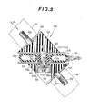
- an engine mount 40 of the present invention there is shown an engine mount 40 of the present invention.
- the engine mount 40 is adapted to be set at a position corresponding to the position where the conventional engine mount 10 (see Fig. 1) is arranged.
- the engine mount 40 of the invention comprises a pair of elastic resilient blocks 42 and 44, such as insulating rubber blocks or the like, each being formed into a right-angled triangular prism. They are arranged so that the respective largest sides thereof face each other leaving therebetween a certain clearance, as shown.
- a retaining plate 46 from which a bolt 48 extends outwardly.
- Vulcanization technique may be employed for securing the retainer 46 to the block 42.
- another retaining plate 50 is secured to one side of the other block 44.
- Another bolt 52 extends outwardly from the retaining plate 50. It is to be noted that the bolts 48 and 50 are aligned on a common axis.
- Two retaining plates 54 and 56 are respectively secured, via vulcanization technique, to the largest sides of the rubber blocks 42 and 44.
- An annular tube 58 constructed of elastic material, such as flexible rubber, is disposed in the space between the retaining plates 54 and 56 in a manner to lie therein.
- the tube 58 is filled with a pressurized air to cause the two blocks 42 and 44 to be biased away in the opposite directions.
- the tube 58 is equipped with an air inlet valve 60 from which air is fed into the tube 58.
- the tube 58 may be filled with other compressible fluid, such as inert gases.
- Designated by numeral 62 is a blocking device which is designed to connect the two rubber blocks 42 and 44 by interposing therebetween another elastic block when the block 44 moves toward the other block 42 by a predetermined distance.
- the blocking device 62 comprises a metal shaft 64 which is secured at its one end to the retaining plate 54 and extends therefrom toward the rubber block 44, passing through the central space of the annular tube 58, as shown.
- the leading end portion of the shaft 64 passes through a circular opening 56a formed in the retaining plate 56 and through a circular opening 44a formed in the block 44, and projects into a cylindrical bore 44b formed in the block 44, the bore 44b being merged with the opening 44a.
- the head portion of the shaft 64 is threaded and the sectional area of the bore 44b is greater than that of the opening 44a which is substantially equal to that of the opening 56a of the retaining plate 56.
- Axially movably received in the bore 44b of the block 44 is a circular metal member 66 having a cylindrical side wall 66a, which is coaxially secured to the shaft 64 by means of a nut 68 screwed to the threaded head portion of the shaft 64.
- the shaft 64 and the circular member 66 are movable together as a unit.
- a generally cylindrical rubber block 70 is coaxially disposed about the major portion of the shaft 64 between spaced two circular flanges 72 and 76 formed on the shaft.
- another circular flange 74 is formed on the shaft 64, which is embedded in the block 70.
- the block 70 comprises a larger diameter portion 70a which is spacedly received in the central space of the annular tube 58 and a smaller diameter portion 70b which is spacedly received in the circular openings 56a and 44a of the retaining plate 56 and the block 44.
- the sum of the axial length of the smaller diameter portion 70b of the block 70 and the thickness of the flange 76 is greater than the sum of the axial lengthes of the openings 56a and 44a.
- the high-frequency small-altitude vibration which originates from the rotation of the engine, is transmitted to the air-filled annular tube 58 through the rubber block 42.
- the vibration is absorbed by compressing the pressurized air in the tube 58.
- the transmission of vibration to the vehicle body is minimized, so that the noises, such as the echoic sounds, are not produced in the vehicle cabin.
- the low-frequency large-altitude vibration which originates from the impacts of foreign things on the road against the road wheels, is transmitted to the lower rubber block 44, thereby making a possibility of bringing the retaining plate 56 into contact with the shoulder portion 70c of the rubber block 70 of the blocking device 62.
- the vibration at the block 44 is transmitted to the upper rubber block 42 through the blocking block 70 during the time when the retaining plate 56 is in contact with the shoulder portion 70c of the block 70.
- the low-frequency large-altitude vibration from the vehicle body is abosrbed steadily by the blocks 44, 70 and 42, by elastically deforming or compressing the same. With this, the undesired "car-shake" phenomenon does not occur.
- the engine mount 40 becomes to have a higher spring constant thereby improving the low-frequency vibration absorbing characteristic.
- the engine mount 40 is so arranged that the axes of the connecting bolts 48 and 52 are aligned coaxially with the main component of inertia of the engine movement, the engine mount 40 can exhibit high resiliency against a force which is applied thereto in a direction normal to the axes of the bolts 48 and 52. Thus, consolidation of the rocking motion and the rolling motion of the engine is prevented.
- the engine mount according to the present invention possesses both the high-frequency vibration absorbing characteristic and the low-frequency vibration absorbing characteristic, to the high levels.
- the high-frequency vibration absorbing characteristic can be easily adjusted by changing the pressure of the fluid (or air) in the annular tube 58.
Applications Claiming Priority (2)
| Application Number | Priority Date | Filing Date | Title |
|---|---|---|---|
| JP1139/81U | 1981-01-07 | ||
| JP1981001139U JPS6134180Y2 (fr) | 1981-01-07 | 1981-01-07 |
Publications (2)
| Publication Number | Publication Date |
|---|---|
| EP0055824A1 true EP0055824A1 (fr) | 1982-07-14 |
| EP0055824B1 EP0055824B1 (fr) | 1985-10-09 |
Family
ID=11493112
Family Applications (1)
| Application Number | Title | Priority Date | Filing Date |
|---|---|---|---|
| EP81109655A Expired EP0055824B1 (fr) | 1981-01-07 | 1981-11-12 | Support de moteur |
Country Status (4)
| Country | Link |
|---|---|
| US (1) | US4399974A (fr) |
| EP (1) | EP0055824B1 (fr) |
| JP (1) | JPS6134180Y2 (fr) |
| DE (1) | DE3172627D1 (fr) |
Cited By (10)
| Publication number | Priority date | Publication date | Assignee | Title |
|---|---|---|---|---|
| GB2153485A (en) * | 1984-01-28 | 1985-08-21 | Tillmann Freudenberg | Active engine suspension unit |
| FR2598764A1 (fr) * | 1986-05-13 | 1987-11-20 | Wolf Woco & Co Franz J | Palier, notamment palier de moteur |
| GB2201222A (en) * | 1986-12-04 | 1988-08-24 | Ivt Ltd | Anti-vibration mounting |
| EP0324693A1 (fr) * | 1988-01-15 | 1989-07-19 | Hutchinson | Supports elastiques de suspension |
| FR2626050A1 (fr) * | 1988-01-15 | 1989-07-21 | Hutchinson | Supports elastiques de suspension |
| WO1989012764A1 (fr) * | 1988-06-13 | 1989-12-28 | Fabreeka International Inc. | Montage pneumatique anti-vibration |
| EP2834471A4 (fr) * | 2012-04-03 | 2016-06-01 | United Technologies Corp | Amortissement de plateforme intérieure d'aube variable |
| WO2016085834A1 (fr) * | 2014-11-25 | 2016-06-02 | Gleason Metrology Systems Corporation | Machine à isolation contre les vibrations |
| KR20190051271A (ko) * | 2017-11-06 | 2019-05-15 | 현대자동차주식회사 | 엔진 장착용 인슐레이터 |
| WO2019148231A1 (fr) * | 2018-02-05 | 2019-08-08 | Euler Rolle Thomas | Amortisseur de vibrations |
Families Citing this family (11)
| Publication number | Priority date | Publication date | Assignee | Title |
|---|---|---|---|---|
| US4629432A (en) * | 1983-02-04 | 1986-12-16 | Brodr. Brunvoll Motorfabrikk A/S | Elastically supported thruster structure |
| DE3421137A1 (de) * | 1984-06-07 | 1985-12-12 | Audi AG, 8070 Ingolstadt | Lager, insbesondere zur lagerung einer brennkraftmaschine in einem kraftfahrzeug |
| FR2670552B1 (fr) * | 1990-12-13 | 1993-02-12 | Caoutchouc Manuf Plastique | Attache hydroelastique de suspension et biellette de liaison geometrique liee a cette attache. |
| DE4114879A1 (de) * | 1991-05-07 | 1992-11-12 | Freudenberg Carl Fa | Federratenumschaltbares motorlager |
| CA2094208A1 (fr) * | 1992-04-28 | 1993-10-29 | Richard D. Hein | Supports elastomeres amortisseurs pre-emballes; procede de fabrication; methode d'installation |
| GB2298260B (en) * | 1995-02-23 | 1998-04-08 | Draftex Ind Ltd | Vibration-damping link |
| DE19718049C1 (de) * | 1997-04-29 | 1998-11-12 | Bayerische Motoren Werke Ag | Lagerung für eine Antriebsmaschine eines Kraftfahrzeugs |
| DE19812387C1 (de) * | 1998-03-20 | 1999-08-12 | Btr Avs Technical Centre Gmbh | Elastisches Lager, insbesondere Motorlager für Kraftfahrzeuge |
| US6431602B1 (en) | 2000-10-23 | 2002-08-13 | Daimlerchrysler Corporation | Method and apparatus for securing an engine mount to a motor vehicle body |
| US8118288B2 (en) * | 2007-10-01 | 2012-02-21 | Briggs & Stratton Corporation | Isolation mount system |
| CN102588487B (zh) * | 2012-02-21 | 2014-05-21 | 喜临门家具股份有限公司 | 一种变径圆柱式气压弹簧 |
Citations (7)
| Publication number | Priority date | Publication date | Assignee | Title |
|---|---|---|---|---|
| DE661895C (de) * | 1934-08-26 | 1938-06-29 | Clemens A Voigt | Lagerungsvorrichtung fuer Maschinenteile, insbesondere an Kraftfahrzeugen |
| US2382372A (en) * | 1942-10-29 | 1945-08-14 | Lord Mfg Co | Resilient mounting |
| US2697578A (en) * | 1951-05-04 | 1954-12-21 | Benjamin B Whittam | Vibration mounting |
| DE1086139B (de) * | 1957-07-05 | 1960-07-28 | Kupfer Asbest Co | Kombinierte mechanisch-pneumatische Federung, insbesondere fuer Kraftfahrzeuge |
| US3008703A (en) * | 1959-07-03 | 1961-11-14 | Gen Tire & Rubber Co | Vibration isolating air spring |
| GB913949A (en) * | 1960-02-15 | 1962-12-28 | Chain Belt Co | A resilient assembly for a vibratory system |
| DE2309276A1 (de) * | 1973-02-24 | 1974-08-29 | Volkswagenwerk Ag | Gasfederanordnung |
Family Cites Families (7)
| Publication number | Priority date | Publication date | Assignee | Title |
|---|---|---|---|---|
| US2705118A (en) * | 1952-01-30 | 1955-03-29 | Lord Mfg Co | Mounting system |
| US4153227A (en) * | 1975-11-28 | 1979-05-08 | Gamaunt Roger L | Fluid self-centering vibration and shock mount |
| DE2616258C3 (de) * | 1976-04-13 | 1978-11-09 | Audi Nsu Auto Union Ag, 7107 Neckarsulm | Gummilager mit hydraulischer Dämpfung |
| DE2823720C2 (de) * | 1978-05-31 | 1983-04-07 | Boge Gmbh, 5208 Eitorf | Zweikammer-Motorlager mit hydraulischer Dämpfung, insbesondere für Kraftfahrzeuge |
| EP0006819B1 (fr) * | 1978-07-03 | 1984-06-27 | Automobiles Peugeot | Dispositif de suspension, notamment de moteur d'un véhicule automobile |
| DE2962362D1 (en) * | 1978-12-07 | 1982-04-29 | Peugeot | Elastic mounting, particularly for the suspension of a vehicle motor |
| DE3027742A1 (de) * | 1980-07-22 | 1982-02-04 | Metzeler Kautschuk GmbH, 8000 München | Zweikammer-motorlager mit hydraulischer daempfung |
-
1981
- 1981-01-07 JP JP1981001139U patent/JPS6134180Y2/ja not_active Expired
- 1981-11-12 DE DE8181109655T patent/DE3172627D1/de not_active Expired
- 1981-11-12 EP EP81109655A patent/EP0055824B1/fr not_active Expired
- 1981-12-10 US US06/329,570 patent/US4399974A/en not_active Expired - Fee Related
Patent Citations (7)
| Publication number | Priority date | Publication date | Assignee | Title |
|---|---|---|---|---|
| DE661895C (de) * | 1934-08-26 | 1938-06-29 | Clemens A Voigt | Lagerungsvorrichtung fuer Maschinenteile, insbesondere an Kraftfahrzeugen |
| US2382372A (en) * | 1942-10-29 | 1945-08-14 | Lord Mfg Co | Resilient mounting |
| US2697578A (en) * | 1951-05-04 | 1954-12-21 | Benjamin B Whittam | Vibration mounting |
| DE1086139B (de) * | 1957-07-05 | 1960-07-28 | Kupfer Asbest Co | Kombinierte mechanisch-pneumatische Federung, insbesondere fuer Kraftfahrzeuge |
| US3008703A (en) * | 1959-07-03 | 1961-11-14 | Gen Tire & Rubber Co | Vibration isolating air spring |
| GB913949A (en) * | 1960-02-15 | 1962-12-28 | Chain Belt Co | A resilient assembly for a vibratory system |
| DE2309276A1 (de) * | 1973-02-24 | 1974-08-29 | Volkswagenwerk Ag | Gasfederanordnung |
Cited By (16)
| Publication number | Priority date | Publication date | Assignee | Title |
|---|---|---|---|---|
| GB2153485A (en) * | 1984-01-28 | 1985-08-21 | Tillmann Freudenberg | Active engine suspension unit |
| FR2598764A1 (fr) * | 1986-05-13 | 1987-11-20 | Wolf Woco & Co Franz J | Palier, notamment palier de moteur |
| GB2201222A (en) * | 1986-12-04 | 1988-08-24 | Ivt Ltd | Anti-vibration mounting |
| EP0324693A1 (fr) * | 1988-01-15 | 1989-07-19 | Hutchinson | Supports elastiques de suspension |
| FR2626050A1 (fr) * | 1988-01-15 | 1989-07-21 | Hutchinson | Supports elastiques de suspension |
| US5102107A (en) * | 1988-01-15 | 1992-04-07 | Hutchinson | Resilient supports for shock absorbing systems |
| WO1989012764A1 (fr) * | 1988-06-13 | 1989-12-28 | Fabreeka International Inc. | Montage pneumatique anti-vibration |
| EP2834471A4 (fr) * | 2012-04-03 | 2016-06-01 | United Technologies Corp | Amortissement de plateforme intérieure d'aube variable |
| WO2016085834A1 (fr) * | 2014-11-25 | 2016-06-02 | Gleason Metrology Systems Corporation | Machine à isolation contre les vibrations |
| EP3224527A1 (fr) * | 2014-11-25 | 2017-10-04 | Gleason Metrology Systems Corporation | Machine à isolation contre les vibrations |
| US20180058538A1 (en) * | 2014-11-25 | 2018-03-01 | Gleason Metrology Systems Corporation | Machine vibration isolation |
| US10480608B2 (en) | 2014-11-25 | 2019-11-19 | Gleason Metrology Systems Corporation | Machine vibration isolation |
| KR20190051271A (ko) * | 2017-11-06 | 2019-05-15 | 현대자동차주식회사 | 엔진 장착용 인슐레이터 |
| KR102440508B1 (ko) | 2017-11-06 | 2022-09-06 | 현대자동차주식회사 | 엔진 장착용 인슐레이터 |
| WO2019148231A1 (fr) * | 2018-02-05 | 2019-08-08 | Euler Rolle Thomas | Amortisseur de vibrations |
| US11320015B2 (en) | 2018-02-05 | 2022-05-03 | Thomas Euler-Rolle | Vibration damper |
Also Published As
| Publication number | Publication date |
|---|---|
| JPS6134180Y2 (fr) | 1986-10-06 |
| EP0055824B1 (fr) | 1985-10-09 |
| US4399974A (en) | 1983-08-23 |
| DE3172627D1 (en) | 1985-11-14 |
| JPS57114720U (fr) | 1982-07-16 |
Similar Documents
| Publication | Publication Date | Title |
|---|---|---|
| US4399974A (en) | Engine mount | |
| US5129479A (en) | Suspension system for an engine and transmission assembly mounted transversely in a vehicle | |
| KR100191104B1 (ko) | 부싱형 진동 댐핑 장치 | |
| CA1301787C (fr) | Amortisseur en elastomere rempli de fluide | |
| KR970001962B1 (ko) | 차량 공조 장치의 압축기용 진동 흡수 장치 | |
| US4725046A (en) | Engine mount | |
| US5263815A (en) | Engine mounting for motor vehicles | |
| JPS6361536B2 (fr) | ||
| EP0077052B1 (fr) | Montage de l'unité motrice de véhicule moteur | |
| JPS629043A (ja) | 防振ゴム装置 | |
| JPS629041A (ja) | 防振ゴム装置 | |
| JP3052853B2 (ja) | パワーユニットの懸架装置 | |
| JPS629040A (ja) | 防振ゴム装置 | |
| US5927678A (en) | Compliant mounting system for automotive components | |
| JPS6217437A (ja) | 防振ゴム | |
| JPH06159897A (ja) | 冷蔵庫におけるコンプレッサの防振支持装置 | |
| JPS61282108A (ja) | 自動車用懸架システム | |
| JPH03244844A (ja) | エアサスペンション | |
| JPS5885704A (ja) | 車輛用懸架装置 | |
| JP7408472B2 (ja) | 防振装置 | |
| JP3319236B2 (ja) | パワーユニット支持装置 | |
| JPS60261729A (ja) | 調整可能の動力機構取付台 | |
| JPS6334963Y2 (fr) | ||
| JPS6129522Y2 (fr) | ||
| JPH094673A (ja) | ストラットマウント |
Legal Events
| Date | Code | Title | Description |
|---|---|---|---|
| PUAI | Public reference made under article 153(3) epc to a published international application that has entered the european phase |
Free format text: ORIGINAL CODE: 0009012 |
|
| 17P | Request for examination filed |
Effective date: 19820430 |
|
| AK | Designated contracting states |
Designated state(s): DE FR GB |
|
| RAP1 | Party data changed (applicant data changed or rights of an application transferred) |
Owner name: NISSAN MOTOR CO., LTD. |
|
| GRAA | (expected) grant |
Free format text: ORIGINAL CODE: 0009210 |
|
| AK | Designated contracting states |
Designated state(s): DE FR GB |
|
| REF | Corresponds to: |
Ref document number: 3172627 Country of ref document: DE Date of ref document: 19851114 |
|
| ET | Fr: translation filed | ||
| PLBE | No opposition filed within time limit |
Free format text: ORIGINAL CODE: 0009261 |
|
| STAA | Information on the status of an ep patent application or granted ep patent |
Free format text: STATUS: NO OPPOSITION FILED WITHIN TIME LIMIT |
|
| 26N | No opposition filed | ||
| PGFP | Annual fee paid to national office [announced via postgrant information from national office to epo] |
Ref country code: FR Payment date: 19911107 Year of fee payment: 11 |
|
| PGFP | Annual fee paid to national office [announced via postgrant information from national office to epo] |
Ref country code: GB Payment date: 19921102 Year of fee payment: 12 |
|
| PGFP | Annual fee paid to national office [announced via postgrant information from national office to epo] |
Ref country code: DE Payment date: 19921123 Year of fee payment: 12 |
|
| PG25 | Lapsed in a contracting state [announced via postgrant information from national office to epo] |
Ref country code: FR Effective date: 19930730 |
|
| REG | Reference to a national code |
Ref country code: FR Ref legal event code: ST |
|
| PG25 | Lapsed in a contracting state [announced via postgrant information from national office to epo] |
Ref country code: GB Effective date: 19931112 |
|
| GBPC | Gb: european patent ceased through non-payment of renewal fee |
Effective date: 19931112 |
|
| PG25 | Lapsed in a contracting state [announced via postgrant information from national office to epo] |
Ref country code: DE Effective date: 19940802 |