EP0053383A1 - Procédé de surveillance commandé par ordinateur de la consommation totale de courant d'un groupe d'utilisateurs de courant - Google Patents
Procédé de surveillance commandé par ordinateur de la consommation totale de courant d'un groupe d'utilisateurs de courant Download PDFInfo
- Publication number
- EP0053383A1 EP0053383A1 EP81109988A EP81109988A EP0053383A1 EP 0053383 A1 EP0053383 A1 EP 0053383A1 EP 81109988 A EP81109988 A EP 81109988A EP 81109988 A EP81109988 A EP 81109988A EP 0053383 A1 EP0053383 A1 EP 0053383A1
- Authority
- EP
- European Patent Office
- Prior art keywords
- power
- process control
- switched
- consumer
- power consumer
- Prior art date
- Legal status (The legal status is an assumption and is not a legal conclusion. Google has not performed a legal analysis and makes no representation as to the accuracy of the status listed.)
- Granted
Links
Images

Classifications
-
- H—ELECTRICITY
- H02—GENERATION; CONVERSION OR DISTRIBUTION OF ELECTRIC POWER
- H02J—CIRCUIT ARRANGEMENTS OR SYSTEMS FOR SUPPLYING OR DISTRIBUTING ELECTRIC POWER; SYSTEMS FOR STORING ELECTRIC ENERGY
- H02J3/00—Circuit arrangements for ac mains or ac distribution networks
- H02J3/12—Circuit arrangements for ac mains or ac distribution networks for adjusting voltage in ac networks by changing a characteristic of the network load
- H02J3/14—Circuit arrangements for ac mains or ac distribution networks for adjusting voltage in ac networks by changing a characteristic of the network load by switching loads on to, or off from, network, e.g. progressively balanced loading
-
- G—PHYSICS
- G05—CONTROLLING; REGULATING
- G05D—SYSTEMS FOR CONTROLLING OR REGULATING NON-ELECTRIC VARIABLES
- G05D23/00—Control of temperature
- G05D23/19—Control of temperature characterised by the use of electric means
-
- H—ELECTRICITY
- H02—GENERATION; CONVERSION OR DISTRIBUTION OF ELECTRIC POWER
- H02J—CIRCUIT ARRANGEMENTS OR SYSTEMS FOR SUPPLYING OR DISTRIBUTING ELECTRIC POWER; SYSTEMS FOR STORING ELECTRIC ENERGY
- H02J2310/00—The network for supplying or distributing electric power characterised by its spatial reach or by the load
- H02J2310/50—The network for supplying or distributing electric power characterised by its spatial reach or by the load for selectively controlling the operation of the loads
- H02J2310/56—The network for supplying or distributing electric power characterised by its spatial reach or by the load for selectively controlling the operation of the loads characterised by the condition upon which the selective controlling is based
- H02J2310/58—The condition being electrical
- H02J2310/60—Limiting power consumption in the network or in one section of the network, e.g. load shedding or peak shaving
-
- H—ELECTRICITY
- H02—GENERATION; CONVERSION OR DISTRIBUTION OF ELECTRIC POWER
- H02J—CIRCUIT ARRANGEMENTS OR SYSTEMS FOR SUPPLYING OR DISTRIBUTING ELECTRIC POWER; SYSTEMS FOR STORING ELECTRIC ENERGY
- H02J2310/00—The network for supplying or distributing electric power characterised by its spatial reach or by the load
- H02J2310/50—The network for supplying or distributing electric power characterised by its spatial reach or by the load for selectively controlling the operation of the loads
- H02J2310/56—The network for supplying or distributing electric power characterised by its spatial reach or by the load for selectively controlling the operation of the loads characterised by the condition upon which the selective controlling is based
- H02J2310/62—The condition being non-electrical, e.g. temperature
- H02J2310/64—The condition being economic, e.g. tariff based load management
-
- Y—GENERAL TAGGING OF NEW TECHNOLOGICAL DEVELOPMENTS; GENERAL TAGGING OF CROSS-SECTIONAL TECHNOLOGIES SPANNING OVER SEVERAL SECTIONS OF THE IPC; TECHNICAL SUBJECTS COVERED BY FORMER USPC CROSS-REFERENCE ART COLLECTIONS [XRACs] AND DIGESTS
- Y02—TECHNOLOGIES OR APPLICATIONS FOR MITIGATION OR ADAPTATION AGAINST CLIMATE CHANGE
- Y02B—CLIMATE CHANGE MITIGATION TECHNOLOGIES RELATED TO BUILDINGS, e.g. HOUSING, HOUSE APPLIANCES OR RELATED END-USER APPLICATIONS
- Y02B70/00—Technologies for an efficient end-user side electric power management and consumption
- Y02B70/30—Systems integrating technologies related to power network operation and communication or information technologies for improving the carbon footprint of the management of residential or tertiary loads, i.e. smart grids as climate change mitigation technology in the buildings sector, including also the last stages of power distribution and the control, monitoring or operating management systems at local level
- Y02B70/3225—Demand response systems, e.g. load shedding, peak shaving
-
- Y—GENERAL TAGGING OF NEW TECHNOLOGICAL DEVELOPMENTS; GENERAL TAGGING OF CROSS-SECTIONAL TECHNOLOGIES SPANNING OVER SEVERAL SECTIONS OF THE IPC; TECHNICAL SUBJECTS COVERED BY FORMER USPC CROSS-REFERENCE ART COLLECTIONS [XRACs] AND DIGESTS
- Y04—INFORMATION OR COMMUNICATION TECHNOLOGIES HAVING AN IMPACT ON OTHER TECHNOLOGY AREAS
- Y04S—SYSTEMS INTEGRATING TECHNOLOGIES RELATED TO POWER NETWORK OPERATION, COMMUNICATION OR INFORMATION TECHNOLOGIES FOR IMPROVING THE ELECTRICAL POWER GENERATION, TRANSMISSION, DISTRIBUTION, MANAGEMENT OR USAGE, i.e. SMART GRIDS
- Y04S20/00—Management or operation of end-user stationary applications or the last stages of power distribution; Controlling, monitoring or operating thereof
- Y04S20/20—End-user application control systems
- Y04S20/222—Demand response systems, e.g. load shedding, peak shaving
-
- Y—GENERAL TAGGING OF NEW TECHNOLOGICAL DEVELOPMENTS; GENERAL TAGGING OF CROSS-SECTIONAL TECHNOLOGIES SPANNING OVER SEVERAL SECTIONS OF THE IPC; TECHNICAL SUBJECTS COVERED BY FORMER USPC CROSS-REFERENCE ART COLLECTIONS [XRACs] AND DIGESTS
- Y04—INFORMATION OR COMMUNICATION TECHNOLOGIES HAVING AN IMPACT ON OTHER TECHNOLOGY AREAS
- Y04S—SYSTEMS INTEGRATING TECHNOLOGIES RELATED TO POWER NETWORK OPERATION, COMMUNICATION OR INFORMATION TECHNOLOGIES FOR IMPROVING THE ELECTRICAL POWER GENERATION, TRANSMISSION, DISTRIBUTION, MANAGEMENT OR USAGE, i.e. SMART GRIDS
- Y04S20/00—Management or operation of end-user stationary applications or the last stages of power distribution; Controlling, monitoring or operating thereof
- Y04S20/20—End-user application control systems
- Y04S20/242—Home appliances
- Y04S20/244—Home appliances the home appliances being or involving heating ventilating and air conditioning [HVAC] units
-
- Y—GENERAL TAGGING OF NEW TECHNOLOGICAL DEVELOPMENTS; GENERAL TAGGING OF CROSS-SECTIONAL TECHNOLOGIES SPANNING OVER SEVERAL SECTIONS OF THE IPC; TECHNICAL SUBJECTS COVERED BY FORMER USPC CROSS-REFERENCE ART COLLECTIONS [XRACs] AND DIGESTS
- Y04—INFORMATION OR COMMUNICATION TECHNOLOGIES HAVING AN IMPACT ON OTHER TECHNOLOGY AREAS
- Y04S—SYSTEMS INTEGRATING TECHNOLOGIES RELATED TO POWER NETWORK OPERATION, COMMUNICATION OR INFORMATION TECHNOLOGIES FOR IMPROVING THE ELECTRICAL POWER GENERATION, TRANSMISSION, DISTRIBUTION, MANAGEMENT OR USAGE, i.e. SMART GRIDS
- Y04S50/00—Market activities related to the operation of systems integrating technologies related to power network operation or related to communication or information technologies
- Y04S50/10—Energy trading, including energy flowing from end-user application to grid
Definitions
- the invention relates to a power-limiting process control of a group of electricity consumers from a certain number of electrical current consumer units.
- Power consumer units are understood here to mean any type of power-consuming devices, apparatus, machines, electrical equipment, etc.
- a consumer group is e.g. around devices, apparatus and / or machines of a technical facility or plant, for example a commercial kitchen. Electricity consumer units that do not belong to the B. drive of the system can also be listened to or particularly added to such a consumer group.
- Cyclically adjustable power consumer units can e.g. be thermostatted. These can be, without any limitation, electric cookers, electric ovens, electrically operated convectors, heating or cooling units and similar devices or apparatus.
- Cyclically regulated power consumer units can be cyclically interrupted or cyclically switched to a level with changed power consumption. No electricity is consumed by the relevant power consumer unit during the interruption time.
- the interruptible and / or reversible to changing power consumption current consumer units can be regulated or controlled in such a way that the functions of the relevant power consumer units do not change significantly by the selected interruption or reversal period with changed power consumption.
- the effective electricity price for a group of electricity consumers basically consists of the so-called work price for each KWh purchased and the performance price, which includes the energy supply costs for the energy supply company (EVU).
- EEU energy supply costs for the energy supply company
- the utility companies either charge according to the maximum tariff or a contractually stipulated special tariff.
- the service price is based on the maximum amount. This is the highest, over a short period of time, e.g. 15 minutes of average performance achieved during the billing cycle.
- a lower and upper limit is set according to certain rules, which the customer is unlikely to fall below or exceed. If the lower limit is exceeded, this limit will also be charged, while if the upper limit is exceeded, an additional fee will be charged for the excess. Setting the upper limit power as low as possible therefore has a favorable effect on the service price.
- the invention is based on the idea that, in many cases, smoothing out structuring current consumption peaks with a process control, preferably in the control or control circuit of interruptible and / or reversible power consumption units that can be changed over, can be temporarily intervened without the function to significantly influence the interrupted or switched electricity consumers. Behavior is particularly favorable, e.g. thermostatted heating or cooling units due to the thermal lag effect.
- the upper limit power can be set with the process control according to the invention the lower, the greater the proportion of interruptible and / or power-switchable power consumer units and the smaller the ratio of on-off time.
- the upper limit power is advantageously placed as close as possible to the total load consumption averaged during a power consumption period.
- an upper limit power which cannot be exceeded by the respective power consumption of the power consumer units can be set to a level which is as low as possible, and in that the smoothing of the currently occurring peak values in the power consumption of the power consumer units below selected upper limit power, the operating characteristic data of the power consumer units are queried in short time intervals and, according to predetermined selection criteria, special power consumer units are briefly interrupted in a uniform order without substantial changes in their functioning, or at least briefly switched to a reduced power consumption.
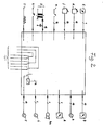
- the operating and signaling elements for the 16 consumers are of the same design for each consumer and arranged on the control panel in 16 columns, which are identified by the numbers 1 to 16. For the sake of simplicity, the same operating and signaling elements are only shown for consumer 1. Corresponding operating and signaling elements are also available for the other consumers 2 to 16 in the same clear arrangement.
- Each consumer thus has a start / stop button "a", a red lamp “b” for signaling a power cut to the consumer, a green lamp “c” for signaling that the consumer is switched on, a first potentiometer “d” in the form of a rotary knob for setting the heating duration for two time units from 0 to 120 minutes and 0 to 12 minutes.
- the selector switch for switching on one of the two time-setting units is labeled "e”.
- a second potentiometer “f” in the form of a further rotary knob is used to set the heating temperature up to which the apparatus is to be heated without interruption and which is to be maintained essentially unchanged during the heating period. It is clear that instead of the potentiometer for the temperature selection can also be a program switch or similar setting device with which a specific temperature profile can be selected during the set heating period. Finally, a time display is marked with "g", which indicates at any time how long the relevant consumer is still in operation. If the operating time has expired, an acoustic signal generator (not shown) is switched on. In addition, the relevant red lamp "a” flashes.
- a display instrument “h” is superior, which shows the remaining energy that is still available and can still be removed without exceeding a selected upper limit for the maximum extractable total energy per unit of time.
- a warning lamp “i” in connection with an acoustic signal generator indicates a malfunction.
- a main switch is shown, which is actuated in case of interruption, the inventive control to switch off in case of interruption, so that then the individual consumer can continue to be driven by itself without interrupting operation in the manual mode cher respectively.
- the control panel is connected to the control according to the invention, which can be accommodated as an electronic control unit in a closable wall housing and which is shown in a block diagram in FIG. 2.
- the electronic control unit is eistungsentised to a certain maximum L E max adjustable, which is indicated by the pointer "h l" of the display instrument "h".
- the other pointer "h 2 " shows the total energy currently consumed by the switched on consumers.
- the angle formed by the two pointers is an analogue measure of the residual energy currently available. It is clear that the residual energy can also be given digitally in numbers.
- the control specialist is furthermore readily aware that the operating and signaling elements indicated here can also be arranged in a different way and that the display elements "g" and “h” can have analog or digital displays for the heating duration still available and for the electrical energy still available at the moment.
- the control unit "St" assigned to the control panel has, as shown in FIG. 2 in a block diagram, 16 first analog inputs for taking over the individual heating times set on potentiometers "d” and 16 second analog inputs for taking over those set on potentiometers "f” in the example Heating temperatures. Furthermore, the control unit has an analog input e for taking over the total power that is currently being consumed. Instead of this analog input for the total power consumption, there can also be 16 analog inputs for the respective individual power consumption of the switched on consumers.
- the control unit also has 16 binary inputs for accepting the start / stop signals, which are emitted by the start / stop buttons "a", and 16 binary inputs for accepting the device-internal switching states "s" of the 16 consumers which are exceeded by means of thermocouples or thermostats an upper temperature limit and be switched on again when a lower temperature limit is exceeded.
- the control unit has a binary input "z" for taking over time pulses from a control center. Instead of specifying a time pulse, an internal clock can also be provided in the control unit.
- control unit has 16 analog outputs for the time displays "g", 16 outputs for controlling the red lamps “b”, 16 analog outputs for controlling the green lamps “c”, 16 outputs for controlling the contactors or the tyristors " T ", about the individual consumer! can be connected to the network or can be switched off from the network, an analog output to display the remaining energy “g” as the difference between the maximum energy that can be drawn and the energy drawn by the switched-on consumer, one Output "b,” for acoustic and / or visual indication that a consumer has ended its operating state and an output "i” for acoustic and / or optical signaling that the system is faulty.
- the control unit takes the consumer into the waiting position and shows this by actuating the relevant red lamp “ b ". If, on the other hand, the start can take place immediately because the required power can be taken directly from the mains or through branches from the switched-on consumers, the control unit automatically triggers the start and controls the relevant green lamp “c" while a signal on the red lamp “b" disappears. Before a consumer starts, its heating duration and heating temperature are set by means of the potentiometers "d” and "f”. The time required for heating is indicated by the time display "g".
- the control according to the invention automatically signals the end of the work of a consumer after the heating period plus any interruptions, without switching him off.
- the time display "g" is then zero.
- the red lamp “b” and an acoustic warning signal “b” go on in addition to the green lamp “c” in order to draw the attention of an operator to the fact that the cooking or baking process in the consumer concerned has been completed and the consumer can be switched off .
- the apparatus must no longer be interrupted to divert electricity.
- the control is designed so that the switching on of an interrupted device has priority over the start of a new one to be switched on.
- the control unit automatically interrupts if the set upper limit for power consumption would be exceeded without it. This condition only applies to thermostated devices. This means that only thermostat-controlled or thermocouple-controlled devices are used for a brief interruption, but not also those electrical kitchen appliances that are not temperature-controlled, e.g. Agitators or similar devices that contain electrically driven parts, the movement of which must not be briefly interrupted.
- these 14 devices can be used in the 2nd stage to make 10 devices each for a total period of approximately Interrupt for 6 minutes, then the current required for the 15th device can be branched off for 60 minutes from 10 devices, the heating time of these 10 devices only being extended by about 6 minutes, which in many cases does not matter.
- T max for the 3rd stage, which is, for example, 2 minutes longer than in the 2nd stage, so that at the end of the 3rd stage all devices which can be briefly interrupted are disconnected from the power for about 8 minutes have been switched off.
- the divertable energy is still not sufficient to supply enough power to one or more connected devices without exceeding a selected upper power consumption limit, then all devices are interrupted in the 4th stage, but with the exception of those that are currently in use are in internal operation, i.e. are switched off due to their internal temperature control because they have exceeded an upper heating temperature.
- the signaling of an interruption can e.g. in that the respective green lamp “c” goes out and the associated red lamp “b” goes on.
- the display of the time remains when interrupted. The interruption is therefore not counted.
- the control according to the invention can e.g. Go through a full polling cycle once every second to determine which of the switched-on devices can be briefly interrupted.
- a different number of devices may have been interrupted per polling cycle, depending on how many of the devices were currently in internal operation. It can happen that the required current is provided by the internally switched-off devices during a cycle, so that additional interruptions are not necessary.
- stage 3 and / or 4 of the above-mentioned multi-stage interrupt cycle is used, but this is only the case in exceptional cases.
- a signal is given after the heating time of an apparatus has ended.
- the relevant red and green lamps “b” and “c” come on and a horn sounds at the same time.
- the time display “g” shows the set heating time.
- the machine in question can now be loaded. After loading, the start / stop button is pressed again. Then the horn sound disappears and the red lamp “b” goes out.
- the set heating time can now begin and the red lamp only comes on again when the apparatus is briefly interrupted by the control according to the invention or the heating time has ended. In the event of a brief interruption, no horn signal appears. As mentioned, this only appears when the start-up time and the entire heating time have ended. The start-up time is not counted towards the heating time.
- the red warning lamp “i” lights up on the control panel and a continuous horn sounds. If the fault cannot be remedied immediately, the manual switch "k” is actuated, as a result of which the interruption circuits are ineffective, while all the devices remain ready for operation with their own timer.
- the control according to the invention sounds a continuous horn when the manual switch "k” is pressed without a fault message.
- This continuous horn can only be switched off by switching off the control or by switching on the manual switch "k” on the control panel.
- control according to the invention is assigned a program memory to which the connected values of each connectable apparatus and its start-up time are fixed are entered.
- program memory has been entered which device must not be interrupted. It is clear that possibilities are expediently provided which allow the data of the program memory to be changed at short notice.
- the control according to the invention can be accommodated in a conventional control cabinet.
- the actual control unit according to FIG. 2 (so-called “intelligent" control unit) of the process control according to the invention for the 16 convectors on which the selected example is based can be a 16-BIT microcomputer which is located on a control card, e.g. a so-called Europe map (TI Europe map calculator) with CMOS memory, real-time clock, A / D converter and 16 input and output ports each.
- the memory and real-time clock are suitably buffered by a battery to protect against power failure.
- control program and the specific data of the individual power consumer units, here the 16 heaters, can be stored in a non-volatile read-only memory EPROM.
- Two additional control cards can be required for the interface circuits for setting the upper limit power, for setting and displaying the real-time clock (option), for displaying the respectively available residual energy and for setting an alarm signal if the control fails or if the upper limit power is exceeded.
- the total power consumed is converted into an analog signal by a current transformer with a downstream measuring transducer.
- All control cards e.g. so-called Euro cards
- All control cards are mounted together with the power supplies in a card magazine.
- the switching states of the heaters to be controlled are e.g. Buffered via any cascadable 220 VAC input modules and queried bit-serially by the microcomputer.
- the control circuits for the device contactors of the heaters are e.g. switched via cascadable 24 VDC output modules and 220 VAC decoupling relays.
- the respective logical switching state is e.g. indicated by LEDs.
- Each device can be removed from the control with a hand switch.
- the input and output modules can be plugged onto base plates.
- a base plate can e.g. accommodate a maximum of 8 modules for 32 channels (input and output mixable). Each heater occupies two input channels and 1 output channel.
- control lines there are at least three control lines per device for transferring the control functions of the microcomputer to the individual heating devices. There is also a common ground wire for all devices. Two control lines are required for each device to query an on-off switch and the thermostat, the third control line is used for looping in the decoupling relay is required in the contactor control circuit.
- the maximum permissible limit power can be varied using a selector switch.
- the currently available remaining power is read on a centrally mounted display instrument. This gives the user the opportunity to find the optimum limit performance for his device configuration.
- An additional module for setting the limit power depending on the time of day can also be available. This option is particularly interesting when peak demand will be in other 'areas that are not subject to control, balanced.
- the control program according to the invention for the microcomputer can be designed in such a way that compliance with the selected limit power has top priority.
- the currently consumed power and the respective switching states of all devices are e.g. measured every second. All switch-off processes (manual or thermostat off) are answered by an additional interruption of the device contactor control circuit. This ensures that a device only switches under the control of the controller.
- Devices in state (4) were interrupted by the controller at an earlier point in time and put in a waiting state. After a certain interruption time (e.g. 60 seconds), these are initially treated internally like connected devices (transition from state (4) to state (3)). If the limit power has not yet been reached, the switching requirements of the devices are met with transitions from (4) to (3) and from (2) to (3) until the limit power is reached. If there is still power available, the other, still interrupted devices are also switched on again. New connections in state (1) after state (3) are only permitted if no device is in state (4) and the limit power is not exceeded.
- a certain interruption time e.g. 60 seconds
- the functionality of the process control is not affected by additional power consumer units that contribute to the overall performance but are not subject to the process control (e.g. devices in continuous operation).
- the functionality of the individual devices that are subject to the process control is also not significantly disturbed by the intervention of the process control.
- the invention is not limited to the above embodiment for 16 convectors in a commercial kitchen. It is clear that the invention can be used with advantage wherever a large number of power-consuming electrical devices have to be switched on at the same time, several of which in turn can be briefly interrupted from the power connection or reversed for reduced power consumption without significant disadvantage, and by the short-term Interruptions without increasing the total current draw such an amount of electricity can be branched that with this at least one additional device can be operated.
- thermostatted power consumer units are particularly suitable, e.g. Cookers, ovens, convectors, heating and cooling units.
- the technical data of the power consumer units that can be connected to a circuit, in particular their power consumption and their start-up times, are known and the question of which of these units should not be switched off for a short period of time in principle, then it is no problem for the electronic control specialist, to build up a process control according to the invention preferably in micro-press technology.
- the power interruption., Per device or apparatus and per interruption can, for example, be a maximum of 60 seconds.
- the invention is of course not limited to such a scanning speed and such an interruption period. It can be advantageous to choose the maximum interruption period shorter than one minute.
- the control unit according to the invention makes it possible for the first time to operate a larger number of electrical units at the same time without taking peak current at particularly expensive tariff times, such as lunchtime, and thus e.g. to make full use of a commercial kitchen with your appliances and equipment, even during expensive tariff times.
Applications Claiming Priority (2)
| Application Number | Priority Date | Filing Date | Title |
|---|---|---|---|
| DE19803045023 DE3045023A1 (de) | 1980-11-28 | 1980-11-28 | Steuerung von mehreren in einer technischen anlage zusammengefassten elektrischen apparaten |
| DE3045023 | 1980-11-28 |
Publications (3)
| Publication Number | Publication Date |
|---|---|
| EP0053383A1 true EP0053383A1 (fr) | 1982-06-09 |
| EP0053383B1 EP0053383B1 (fr) | 1985-06-05 |
| EP0053383B2 EP0053383B2 (fr) | 1991-12-27 |
Family
ID=6117888
Family Applications (1)
| Application Number | Title | Priority Date | Filing Date |
|---|---|---|---|
| EP81109988A Expired - Lifetime EP0053383B2 (fr) | 1980-11-28 | 1981-11-28 | Procédé de surveillance commandé par ordinateur de la consommation totale de courant d'un groupe d'utilisateurs de courant |
Country Status (2)
| Country | Link |
|---|---|
| EP (1) | EP0053383B2 (fr) |
| DE (2) | DE3045023A1 (fr) |
Cited By (13)
| Publication number | Priority date | Publication date | Assignee | Title |
|---|---|---|---|---|
| FR2568081A1 (fr) * | 1984-07-19 | 1986-01-24 | Tibiletti Societe Nouvelle | Procede pour distribuer la puissance electrique apres analyse des besoins dans uns installation de chauffage comportant des ensembles de resistances electriques et dispositif de mise en oeuvre. |
| EP0225657A1 (fr) * | 1985-11-08 | 1987-06-16 | Philips Patentverwaltung GmbH | Procédé de commande de plusieurs charges électriques |
| EP0913905A2 (fr) * | 1997-11-03 | 1999-05-06 | Voss GrossküchenSysteme GmbH | Méthode et dispositif pour limiter la consommation totale d'une pluralité de charges électriques d'un réseau électrique |
| DE19842043A1 (de) * | 1998-09-14 | 2000-03-16 | Gerda Schmidt | Verfahren und Vorrichtung zur automatischen und verbraucherorientierten Leistungsminimierung elektrischer Verbraucher |
| EP1176690A2 (fr) * | 2000-07-28 | 2002-01-30 | Thomas Pfrieme | Dispositif et procédé pour la distribution de charge électrique parmi plusieurs consommateurs de charge |
| DE102007062287A1 (de) * | 2007-12-21 | 2009-06-25 | Manroland Ag | Verfahren zum Herstellen eines Druckprodukts |
| ES2340127A1 (es) * | 2008-10-27 | 2010-05-28 | Industrias Royal Termic, S.L | Procedimiento de gestion de un consumo energetico total de un conjunto de al menos dos radiadores. |
| DE102011054363A1 (de) * | 2011-10-10 | 2013-04-11 | DASGIP Information and Process Technology GmbH | Verfahren zum geregelten Betreiben einer biotechnologischen Vorrichtung und biotechnologische Vorrichtung |
| EP2628419A1 (fr) | 2012-02-20 | 2013-08-21 | G.D.V. Productions | Sauteuse basculante à induction |
| DE102014004362A1 (de) * | 2014-03-27 | 2015-10-01 | Heidelberger Druckmaschinen Ag | Verfahren zu Reduzierung der Spitzenlast in einer Druckmaschine |
| US9745547B2 (en) | 2011-10-10 | 2017-08-29 | Dasgip Information And Technology Gmbh | Method for controlled operation of a biotechnological apparatus and bioreactor system |
| US9760956B2 (en) | 2011-04-08 | 2017-09-12 | Sma Solar Technology Ag | Optimized load management |
| CN116700038A (zh) * | 2023-08-02 | 2023-09-05 | 深圳市虎一科技有限公司 | 具有调节功能的家用厨电系统的控制方法、装置及系统 |
Families Citing this family (5)
| Publication number | Priority date | Publication date | Assignee | Title |
|---|---|---|---|---|
| DE19530825C2 (de) * | 1995-08-22 | 1999-04-29 | Dieter Rupert Bruederl | Verfahren und Vorrichtung zur Energieoptimierung bei einem Energieverteilungssystem |
| DE19530826C1 (de) * | 1995-08-22 | 1997-01-23 | Dieter Rupert Bruederl | Verfahren und Vorrichtung zur Optimierung der Leistungsaufnahme bei einem Energieverteilungssystem |
| DE19817191C2 (de) * | 1998-04-17 | 2001-07-05 | Thomas Frank | Verfahren zum Regeln der Gesamtleistung von energietechnischen Anlagen, insbesondere einer Gruppe von elektrischen Verbrauchern |
| DE102004046758A1 (de) | 2004-09-24 | 2006-04-06 | Meiko Maschinenbau Gmbh & Co. Kg | Verfahren und Anordnung zum energiesparenden Betrieb von Spülmaschinen |
| DE102014005240A1 (de) * | 2014-04-10 | 2015-10-15 | Joachim Leppig | Verfahren zum Betreiben einer Produktions- und Verkaufseinrichtung für Waren des Einzelhandels |
Citations (5)
| Publication number | Priority date | Publication date | Assignee | Title |
|---|---|---|---|---|
| DE2315208A1 (de) * | 1972-03-27 | 1973-10-11 | George Donald Forman | Steuerlogik fuer elektrische stromversorgungsanlagen |
| DE2419663A1 (de) * | 1973-12-18 | 1975-06-26 | Daetwyler Ag | Einrichtung zur koordination und begrenzung des gesamtbedarfes an elektrischer energie von mehreren energieverbrauchern |
| US4090062A (en) * | 1976-07-12 | 1978-05-16 | Phillips Control Corp. | Energy demand controller and method therefor |
| FR2433254A1 (fr) * | 1978-08-11 | 1980-03-07 | Courtois Andre | Dispositif electronique de repartition sequentielle de l'energie electrique |
| US4216384A (en) * | 1977-12-09 | 1980-08-05 | Directed Energy Systems, Inc. | System for monitoring and controlling electric power consumption |
-
1980
- 1980-11-28 DE DE19803045023 patent/DE3045023A1/de not_active Withdrawn
-
1981
- 1981-11-28 EP EP81109988A patent/EP0053383B2/fr not_active Expired - Lifetime
- 1981-11-28 DE DE8181109988T patent/DE3170892D1/de not_active Expired
Patent Citations (5)
| Publication number | Priority date | Publication date | Assignee | Title |
|---|---|---|---|---|
| DE2315208A1 (de) * | 1972-03-27 | 1973-10-11 | George Donald Forman | Steuerlogik fuer elektrische stromversorgungsanlagen |
| DE2419663A1 (de) * | 1973-12-18 | 1975-06-26 | Daetwyler Ag | Einrichtung zur koordination und begrenzung des gesamtbedarfes an elektrischer energie von mehreren energieverbrauchern |
| US4090062A (en) * | 1976-07-12 | 1978-05-16 | Phillips Control Corp. | Energy demand controller and method therefor |
| US4216384A (en) * | 1977-12-09 | 1980-08-05 | Directed Energy Systems, Inc. | System for monitoring and controlling electric power consumption |
| FR2433254A1 (fr) * | 1978-08-11 | 1980-03-07 | Courtois Andre | Dispositif electronique de repartition sequentielle de l'energie electrique |
Cited By (21)
| Publication number | Priority date | Publication date | Assignee | Title |
|---|---|---|---|---|
| FR2568081A1 (fr) * | 1984-07-19 | 1986-01-24 | Tibiletti Societe Nouvelle | Procede pour distribuer la puissance electrique apres analyse des besoins dans uns installation de chauffage comportant des ensembles de resistances electriques et dispositif de mise en oeuvre. |
| EP0225657A1 (fr) * | 1985-11-08 | 1987-06-16 | Philips Patentverwaltung GmbH | Procédé de commande de plusieurs charges électriques |
| EP0913905A2 (fr) * | 1997-11-03 | 1999-05-06 | Voss GrossküchenSysteme GmbH | Méthode et dispositif pour limiter la consommation totale d'une pluralité de charges électriques d'un réseau électrique |
| EP0913905A3 (fr) * | 1997-11-03 | 1999-12-08 | Voss GrossküchenSysteme GmbH | Méthode et dispositif pour limiter la consommation totale d'une pluralité de charges électriques d'un réseau électrique |
| DE19842043A1 (de) * | 1998-09-14 | 2000-03-16 | Gerda Schmidt | Verfahren und Vorrichtung zur automatischen und verbraucherorientierten Leistungsminimierung elektrischer Verbraucher |
| DE19842043B4 (de) * | 1998-09-14 | 2005-11-17 | Gerda Schmidt | Verfahren zur automatischen und verbraucherorientierten Minimierung des Gesamtstromverbrauchs und der Leistungsspitze einer Gruppe von an einem Leistungsversorgungsnetz angeschlossenen einzelnen elektrischen Verbrauchern |
| EP1176690A2 (fr) * | 2000-07-28 | 2002-01-30 | Thomas Pfrieme | Dispositif et procédé pour la distribution de charge électrique parmi plusieurs consommateurs de charge |
| EP1176690A3 (fr) * | 2000-07-28 | 2005-02-16 | Thomas Pfrieme | Dispositif et procédé pour la distribution de charge électrique parmi plusieurs consommateurs de charge |
| DE102007062287A1 (de) * | 2007-12-21 | 2009-06-25 | Manroland Ag | Verfahren zum Herstellen eines Druckprodukts |
| EP2072257B2 (fr) † | 2007-12-21 | 2020-08-05 | manroland Goss web systems GmbH | Procédé de fabrication d'un produit d'impression |
| ES2340127A1 (es) * | 2008-10-27 | 2010-05-28 | Industrias Royal Termic, S.L | Procedimiento de gestion de un consumo energetico total de un conjunto de al menos dos radiadores. |
| US9760956B2 (en) | 2011-04-08 | 2017-09-12 | Sma Solar Technology Ag | Optimized load management |
| DE102012103081B4 (de) | 2011-04-08 | 2021-12-30 | Sma Solar Technology Ag | Optimiertes Lastmanagement |
| DE102011054363B4 (de) * | 2011-10-10 | 2015-07-09 | DASGIP Information and Process Technology GmbH | Verfahren zum geregelten Betreiben einer biotechnologischen Vorrichtung und biotechnologische Vorrichtung |
| US9745547B2 (en) | 2011-10-10 | 2017-08-29 | Dasgip Information And Technology Gmbh | Method for controlled operation of a biotechnological apparatus and bioreactor system |
| DE102011054363A1 (de) * | 2011-10-10 | 2013-04-11 | DASGIP Information and Process Technology GmbH | Verfahren zum geregelten Betreiben einer biotechnologischen Vorrichtung und biotechnologische Vorrichtung |
| US10934516B2 (en) | 2011-10-10 | 2021-03-02 | Dasgip Information And Technology Gmbh | Method for controlled operation of a biotechnological apparatus and bioreactor system |
| EP2628419A1 (fr) | 2012-02-20 | 2013-08-21 | G.D.V. Productions | Sauteuse basculante à induction |
| DE102014004362A1 (de) * | 2014-03-27 | 2015-10-01 | Heidelberger Druckmaschinen Ag | Verfahren zu Reduzierung der Spitzenlast in einer Druckmaschine |
| CN116700038A (zh) * | 2023-08-02 | 2023-09-05 | 深圳市虎一科技有限公司 | 具有调节功能的家用厨电系统的控制方法、装置及系统 |
| CN116700038B (zh) * | 2023-08-02 | 2023-10-13 | 深圳市虎一科技有限公司 | 具有调节功能的家用厨电系统的控制方法、装置及系统 |
Also Published As
| Publication number | Publication date |
|---|---|
| EP0053383B1 (fr) | 1985-06-05 |
| EP0053383B2 (fr) | 1991-12-27 |
| DE3045023A1 (de) | 1982-07-01 |
| DE3170892D1 (en) | 1985-07-11 |
Similar Documents
| Publication | Publication Date | Title |
|---|---|---|
| EP0053383A1 (fr) | Procédé de surveillance commandé par ordinateur de la consommation totale de courant d'un groupe d'utilisateurs de courant | |
| EP0648005B1 (fr) | Appareil pour la limitation de puissance absorbée par des appareils ménagers alimentés par l'intermédiaire d'un raccord d'alimentation en énergie | |
| DE3003453C2 (fr) | ||
| DE3003452C2 (fr) | ||
| EP1004860B1 (fr) | Balance electronique avec foncionnement en mode veille | |
| DE2806426A1 (de) | Belastungsregler | |
| EP0099043B1 (fr) | Système pour commander la consommation d'énergie électrique, de préférence pour l'usage domestique | |
| DE19842043B4 (de) | Verfahren zur automatischen und verbraucherorientierten Minimierung des Gesamtstromverbrauchs und der Leistungsspitze einer Gruppe von an einem Leistungsversorgungsnetz angeschlossenen einzelnen elektrischen Verbrauchern | |
| EP0464423B1 (fr) | Dispositif pour commander la consommation totale d'énergie d'un récepteur de courant | |
| DE3426542C2 (fr) | ||
| DE2557133B2 (de) | Anordnung zur leistungsregelung elektrischer kochplatten | |
| DE2721630A1 (de) | Schaltungsanordnung zur ansteuerung eines schrittmotors nach dem chopper- prinzip | |
| GB2188799A (en) | Control system for electric power distribution | |
| WO1992009024A1 (fr) | Regulateur de tension | |
| DE19530825C2 (de) | Verfahren und Vorrichtung zur Energieoptimierung bei einem Energieverteilungssystem | |
| DE2922161A1 (de) | Raumthermostat | |
| DE3345991C2 (fr) | ||
| DE1588439C (de) | Auswahlschaltwerk zur Hochstlastuber wachung | |
| DE2247414B2 (de) | Verfahren zur ueberwachung und begrenzung des verbrauchs von energie | |
| DE19844844C2 (de) | Kreiselpumpenaggregat | |
| DE2908509A1 (de) | Steuerungseinrichtung fuer ein haushaltsgeraet | |
| DE3736658C2 (fr) | ||
| DE642550C (de) | Vorrichtung zur Erzielung eines gewissen Toleranzbereichs bei Einrichtungen zur selbsttaetigen Begrenzung der Leistung einer elektrischen Anlage | |
| AT407459B (de) | Elektrisch beheizter speicher | |
| EP0236372A1 (fr) | Agencement de connexion pour l'alimentation en courant d'appareils electriques ou electroniques de commande ou de reglage |
Legal Events
| Date | Code | Title | Description |
|---|---|---|---|
| PUAI | Public reference made under article 153(3) epc to a published international application that has entered the european phase |
Free format text: ORIGINAL CODE: 0009012 |
|
| AK | Designated contracting states |
Designated state(s): AT BE CH DE FR GB IT LU NL SE |
|
| 17P | Request for examination filed |
Effective date: 19821208 |
|
| GRAA | (expected) grant |
Free format text: ORIGINAL CODE: 0009210 |
|
| AK | Designated contracting states |
Designated state(s): CH DE FR GB LI |
|
| RBV | Designated contracting states (corrected) |
Designated state(s): CH DE FR GB LI |
|
| REF | Corresponds to: |
Ref document number: 3170892 Country of ref document: DE Date of ref document: 19850711 |
|
| ET | Fr: translation filed | ||
| PLBI | Opposition filed |
Free format text: ORIGINAL CODE: 0009260 |
|
| 26 | Opposition filed |
Opponent name: SAW VERTRIEBS-GMBH Effective date: 19851207 |
|
| PUAH | Patent maintained in amended form |
Free format text: ORIGINAL CODE: 0009272 |
|
| STAA | Information on the status of an ep patent application or granted ep patent |
Free format text: STATUS: PATENT MAINTAINED AS AMENDED |
|
| 27A | Patent maintained in amended form |
Effective date: 19911227 |
|
| AK | Designated contracting states |
Kind code of ref document: B2 Designated state(s): CH DE FR GB LI |
|
| REG | Reference to a national code |
Ref country code: CH Ref legal event code: AEN |
|
| ET3 | Fr: translation filed ** decision concerning opposition | ||
| PGFP | Annual fee paid to national office [announced via postgrant information from national office to epo] |
Ref country code: CH Payment date: 19951027 Year of fee payment: 15 |
|
| PGFP | Annual fee paid to national office [announced via postgrant information from national office to epo] |
Ref country code: GB Payment date: 19951030 Year of fee payment: 15 |
|
| PG25 | Lapsed in a contracting state [announced via postgrant information from national office to epo] |
Ref country code: GB Effective date: 19961128 |
|
| PG25 | Lapsed in a contracting state [announced via postgrant information from national office to epo] |
Ref country code: LI Effective date: 19961130 Ref country code: CH Effective date: 19961130 |
|
| APAC | Appeal dossier modified |
Free format text: ORIGINAL CODE: EPIDOS NOAPO |
|
| APAC | Appeal dossier modified |
Free format text: ORIGINAL CODE: EPIDOS NOAPO |
|
| REG | Reference to a national code |
Ref country code: CH Ref legal event code: PL |
|
| GBPC | Gb: european patent ceased through non-payment of renewal fee |
Effective date: 19961128 |
|
| PGFP | Annual fee paid to national office [announced via postgrant information from national office to epo] |
Ref country code: FR Payment date: 19981012 Year of fee payment: 18 |
|
| PG25 | Lapsed in a contracting state [announced via postgrant information from national office to epo] |
Ref country code: FR Free format text: LAPSE BECAUSE OF NON-PAYMENT OF DUE FEES Effective date: 20000731 |
|
| REG | Reference to a national code |
Ref country code: FR Ref legal event code: ST |
|
| PGFP | Annual fee paid to national office [announced via postgrant information from national office to epo] |
Ref country code: DE Payment date: 20010327 Year of fee payment: 20 |
|
| APAH | Appeal reference modified |
Free format text: ORIGINAL CODE: EPIDOSCREFNO |
|
| PLAB | Opposition data, opponent's data or that of the opponent's representative modified |
Free format text: ORIGINAL CODE: 0009299OPPO |