EP0464423B1 - Dispositif pour commander la consommation totale d'énergie d'un récepteur de courant - Google Patents
Dispositif pour commander la consommation totale d'énergie d'un récepteur de courant Download PDFInfo
- Publication number
- EP0464423B1 EP0464423B1 EP91109755A EP91109755A EP0464423B1 EP 0464423 B1 EP0464423 B1 EP 0464423B1 EP 91109755 A EP91109755 A EP 91109755A EP 91109755 A EP91109755 A EP 91109755A EP 0464423 B1 EP0464423 B1 EP 0464423B1
- Authority
- EP
- European Patent Office
- Prior art keywords
- interval
- value
- limit value
- current flow
- processing unit
- Prior art date
- Legal status (The legal status is an assumption and is not a legal conclusion. Google has not performed a legal analysis and makes no representation as to the accuracy of the status listed.)
- Expired - Lifetime
Links
Images

Classifications
-
- H—ELECTRICITY
- H02—GENERATION; CONVERSION OR DISTRIBUTION OF ELECTRIC POWER
- H02J—ELECTRIC POWER NETWORKS; CIRCUIT ARRANGEMENTS OR SYSTEMS FOR SUPPLYING OR DISTRIBUTING ELECTRIC POWER; SYSTEMS FOR STORING ELECTRIC ENERGY
- H02J3/00—Circuit arrangements for AC mains or AC distribution networks
- H02J3/17—Demand-responsive operation of AC power transmission or distribution networks
-
- H—ELECTRICITY
- H02—GENERATION; CONVERSION OR DISTRIBUTION OF ELECTRIC POWER
- H02J—ELECTRIC POWER NETWORKS; CIRCUIT ARRANGEMENTS OR SYSTEMS FOR SUPPLYING OR DISTRIBUTING ELECTRIC POWER; SYSTEMS FOR STORING ELECTRIC ENERGY
- H02J2105/00—Networks for supplying or distributing electric power characterised by their spatial reach or by the load
- H02J2105/50—Networks for supplying or distributing electric power characterised by their spatial reach or by the load for selectively controlling the operation of the loads
- H02J2105/52—Networks for supplying or distributing electric power characterised by their spatial reach or by the load for selectively controlling the operation of the loads for limitation of the power consumption in the networks or in one section of the networks, e.g. load shedding or peak shaving
-
- H—ELECTRICITY
- H02—GENERATION; CONVERSION OR DISTRIBUTION OF ELECTRIC POWER
- H02J—ELECTRIC POWER NETWORKS; CIRCUIT ARRANGEMENTS OR SYSTEMS FOR SUPPLYING OR DISTRIBUTING ELECTRIC POWER; SYSTEMS FOR STORING ELECTRIC ENERGY
- H02J2105/00—Networks for supplying or distributing electric power characterised by their spatial reach or by the load
- H02J2105/50—Networks for supplying or distributing electric power characterised by their spatial reach or by the load for selectively controlling the operation of the loads
- H02J2105/57—Networks for supplying or distributing electric power characterised by their spatial reach or by the load for selectively controlling the operation of the loads according to a pre-established time schedule
-
- Y—GENERAL TAGGING OF NEW TECHNOLOGICAL DEVELOPMENTS; GENERAL TAGGING OF CROSS-SECTIONAL TECHNOLOGIES SPANNING OVER SEVERAL SECTIONS OF THE IPC; TECHNICAL SUBJECTS COVERED BY FORMER USPC CROSS-REFERENCE ART COLLECTIONS [XRACs] AND DIGESTS
- Y02—TECHNOLOGIES OR APPLICATIONS FOR MITIGATION OR ADAPTATION AGAINST CLIMATE CHANGE
- Y02B—CLIMATE CHANGE MITIGATION TECHNOLOGIES RELATED TO BUILDINGS, e.g. HOUSING, HOUSE APPLIANCES OR RELATED END-USER APPLICATIONS
- Y02B70/00—Technologies for an efficient end-user side electric power management and consumption
- Y02B70/30—Systems integrating technologies related to power network operation and communication or information technologies for improving the carbon footprint of the management of residential or tertiary loads, i.e. smart grids as climate change mitigation technology in the buildings sector, including also the last stages of power distribution and the control, monitoring or operating management systems at local level
- Y02B70/3225—Demand response systems, e.g. load shedding, peak shaving
-
- Y—GENERAL TAGGING OF NEW TECHNOLOGICAL DEVELOPMENTS; GENERAL TAGGING OF CROSS-SECTIONAL TECHNOLOGIES SPANNING OVER SEVERAL SECTIONS OF THE IPC; TECHNICAL SUBJECTS COVERED BY FORMER USPC CROSS-REFERENCE ART COLLECTIONS [XRACs] AND DIGESTS
- Y04—INFORMATION OR COMMUNICATION TECHNOLOGIES HAVING AN IMPACT ON OTHER TECHNOLOGY AREAS
- Y04S—SYSTEMS INTEGRATING TECHNOLOGIES RELATED TO POWER NETWORK OPERATION, COMMUNICATION OR INFORMATION TECHNOLOGIES FOR IMPROVING THE ELECTRICAL POWER GENERATION, TRANSMISSION, DISTRIBUTION, MANAGEMENT OR USAGE, i.e. SMART GRIDS
- Y04S20/00—Management or operation of end-user stationary applications or the last stages of power distribution; Controlling, monitoring or operating thereof
- Y04S20/20—End-user application control systems
- Y04S20/222—Demand response systems, e.g. load shedding, peak shaving
Definitions
- the invention relates to an arrangement for controlling the total energy consumption (EV) of an electricity consumer, in which both a controllable switch and a current flow signal supplying current flow sensor are switched on in several circuits for each consumer device in addition to an overload switch are and in which the current flow signals, possibly via intermediate stages such as amplifiers, are fed to a processing unit (computer), wherein, preferably from the current flow signals, a sum signal is formed and the controllable switches are connected to the processing unit such that at least one of the switches is actuated when the sum signal exceeds a limit value or when other switch-off criteria are present, the current flow sensor, the controllable switch and the overload switch being combined to form a unit acting as a sensor actuator, as is known from DE 32 26 544 A1 is.
- a processing unit computer
- This known arrangement relates to a system for controlling the electrical energy consumption (total power consumption), preferably in households, in which the current is measured in each circuit to the consumer devices and the connection or disconnection of consumers after the comparison in a measurement period related electrical energy with a limit value.
- the current sensors in the individual circuits are used to determine the current flow times in the individual circuits.
- the new electricity meters can have a maximum monitor, which is coupled with a timer at the same time.
- a basic fee of about DM 300 to DM 400 per kilowatt should be in question, so that it is very interesting whether the peak consumption in private households is, for example, 4 kW or 8 kW with simultaneous operation of all large consumers.
- the actual acceptance performance is therefore an important cost component, which the customer can only influence in extreme discipline at any moment. Larger commercial facilities are already overwhelmed by this.
- the goal is to achieve the lowest possible fluctuations in electricity consumption over the course of the day and, if necessary, over the year for individual customers, and also to avoid exceeding a low average value or to burden it with tariff surcharges.
- the invention has for its object to provide an arrangement of the type mentioned in such a way that it is easy to install, easy to use and manufacture with little economic effort and works with improved power recording.
- the customer determines his actual value from the sum of all connected consumers, so he does not need his own separate total counter and is independent of the utility company.
- the required miniaturization which enables it to be used instead of the previous miniature circuit breaker, is achieved by a new technology that leaves the previous strategy of the device manufacturers, the splitting of the individual functions into separate units (modular systems), in favor of higher forms of integration.
- the limit value for a subsequent interval from the energy consumption value in at least one previous interval by means of the Processing unit is determined according to a predetermined program.
- a forecast is therefore given for the last part of a period of time that is decisive for the tariff calculation based on the previous larger part, so that as little part of the permissible energy consumption as possible remains unused by the electricity company.
- the time period TP is increased over time, e.g. over the whole year, shifted by one interval TI.
- the energy consumption in total or in individual circuits can be continuously recorded and evaluated for a forecast in the last interval of the time period specified by the tariff design.
- the total value can simply depend on the current supplied in a manner known per se. In order to meet special requirements on the part of the electricity works, the total value can also depend on the reactive power supplied or the active power supplied.
- a particularly precise adjustment of the actual consumption to the value permitted according to the tariff results if one also continuously measures the energy consumed within the subsequent (last) interval for which a forecast has been made and the permitted limit value corresponding to that until the end of this Interval of still consumable energy changes.
- the limit value can be adjusted continuously; Expediently, the adaptation is carried out in descending stages, the duration of these stages being one or more minutes in order to keep the effort low, but nevertheless to do justice to the changes in consumption that are possible in practical operation.
- the design is such that if the limit value is exceeded by the current energy consumption of at least one of the connected devices, consumption is reduced or completely or partially switched off in accordance with a certain order of priority, or entirely if the limit value is undershot by more than a predetermined threshold value or partially turned on. So on the one hand prevents the given limits from being exceeded, but on the other hand also avoids that too much consumer load remains switched off and the given framework of energy supply is thus not fully utilized.
- the processing unit can easily record such switch-off processes, and it can also switch on again, if necessary, in a different order than that which was provided for the switch-off.
- At least one of the consumer devices can be operated at intervals of e.g. periodically switched on and off for a few seconds or minutes. It is also possible to periodically switch two or more consumers on and off alternately: this way the total load can be reduced without one of the devices being switched off completely.
- a reduction in the load is also possible in that at least one of the consumer devices in phase control is switched on in a shortened manner in each alternating current period and switched off again.
- the threshold value for switching on the consumer when approaching the limit value should be kept low and may correspond to an energy consumption of a certain percentage, for example 1 to 3%, of the limit value output. If the limit power corresponds to 4 kW, another consumer device can be switched on if the total energy consumption drops below around 3,900 watts, corresponding to a reduction of 2.5%.
- both a current sensor and a controllable switch can be switched on in several circuits and that the signals of all current sensors are fed to a control unit to which the controllable switches are connected such that at least one of the switches is actuated and the associated circuit is interrupted when the sum signal exceeds the limit.
- the current flow sensor is useful as an inductive sensor, e.g. as a current transformer. An intervention in the line carrying the consumer current is then not necessary.
- the controllable switch can be a magnetic switch controllable by an electric current, for example a contactor. However, it can also be designed as an electronically controllable element, for example a thyristor; Such a configuration is particularly suitable when periodic switching on and off at intervals or in phase cycles is to be carried out.
- the processing unit a program stage with an input part, an input unit, a limit value stage, a timer and an output unit can be combined in a starter device, if appropriate together with further appropriate circuit stages.
- the signals of all current sensors are processed in the control unit and information is thus given about the total load caused by the consumer devices.
- the signals are created according to a program that can be entered or modified by the user, the electricity consumer; it can be determined in which order one or more consumer devices are switched off or their power consumption is reduced if the limit value is exceeded.
- the program is used to implement switch-on interlocks and / or timeout controls for any consumer devices or groups thereof according to a predetermined priority.
- the ranking does not have to be fixed, it can be adjusted according to additional conditions.
- the priority for a particular consumer device can be selected differently at different times; In the midday hours the kitchen stove can be privileged, in the evening an electric boiler for showering and in the night or in the afternoon the washing machine or dishwasher or a hot water tank, which then supplies preheated water during the day, if necessary without reheating.
- the setpoints that play a role here can be saved permanently or temporarily (by ROM and RAM).
- a controllable switch can not only cause a complete interruption of the power supply, but it is also possible to switch to a lower power consumption.
- one and / or the other plate can be switched off from the kitchen stove with a high total load, but at least one plate should remain switched on for a longer cooking process.
- the respective consumption can be sensed by the assigned current sensor and, if the current requirement of this plate is reduced, another one can be switched on temporarily.
- Lamp power circuits can be continuously set in terms of their power consumption analogously to conventional dimming devices, which is easy to implement by means of a controlled semiconductor switch (thyristor) instead of a magnetic switch.
- thyristor controlled semiconductor switch
- the program can be set or subsequently changed using a keyboard or a magnetic card, which is activated via a built-in reading device.
- the latter solution is particularly suitable for cases in which a new load profile is to be assigned to the customer from the power plant.
- a particularly simple embodiment results when the controllable switch, the current flow sensor and the overload switch for a circuit are combined to form one structural unit.
- the current flow sensor can also be called a sensor and sends the current flow signal to the outside.
- the controllable switch receives a signal from the outside and then opens or closes a contact connection.
- Such an assembly thus acts as a sensor actuator.
- Such a unit is particularly useful when retrofitting is to be done; then the assembly can also be mechanically arranged in the place of a previous fuse, so that major renovation work is not necessary.
- the structural unit can be designed in such a way that it can be installed in the existing electrical distribution board at the location of the previously required securing element, which can thus be converted in a simple manner for a new tariff system.
- At least one switch interrupting the circuit can be controlled on the one hand for opening and closing by the processing unit and on the other hand can be opened automatically in the event of overload, but can only be closed again by hand.
- only one contact path is installed in the circuit, but on the one hand it can act automatically as a fuse protection in the circuit in question, and on the other hand, it can be opened and closed again from the outside for the desired influencing of the total energy consumption.
- Such a switch is preferably designed as a normally closed contact, so that it normally allows the current to flow unimpeded through the circuit without any interference.
- the contact path can then be coupled, on the one hand, to a first drive device which can be controlled by the processing unit, so that the circuit is interrupted and closed again.
- the contact can be opened by a second drive device, which becomes effective when overloaded and then or the like by means of a catch. is held in the open state; the catch can only be released by hand, as is the case with normal securing.
- An element dependent on the heating or an element magnetically controlled by the current can be used to actuate this second drive device in a manner known per se.
- the two drive devices act in the same direction, namely opening the contact, so that mutual interference is not possible; the closure can be effected by a spring.
- Appropriate coupling stages can be used to supply the processing stage with signals from the outside, for example control signals from the electricity company or a maximum monitor that monitors the maximum power consumption in a certain network area.
- an arrangement according to the invention with a ripple control receiver can receive EVU signals, which are usually of low frequency.
- the control unit can also receive other commands with the aid of a receiver for higher-frequency network bus signals, For example, the control command from a remote maximum guard, which is installed in a main distribution, for example, and these commands can be evaluated in a suitable manner via the program and can be activated, for example, for setting the limit value.
- a current sensor is expediently coupled to each phase line, and the three current flow signals are fed to the processing device.
- Different loads of individual phases can also be recorded, e.g. in an electric cooker or in an electric hot water tank as a result of temperature control.
- the controlled switches of this three-phase consumer are expediently coupled to one another, so that if the limit value is exceeded, all three phase lines of this consumer are switched off.
- the parts of an arrangement according to the invention can be attached together on the control panel; this is particularly recommended for new systems.
- the connection can then be made by cables that are firmly attached to the units and are connected to the control unit with the processing device by means of plugs.
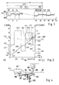
- intervals of the same interval width TI and with a continuous interval number Z beginning with 1 are indicated over a time axis t by short vertical lines.
- Curve 105 shows the course of the total energy consumption EV of an electricity consumer in accordance with the power L fluctuating by switching on or switching off consumer devices or by changing their load.
- the current energy consumption can easily be determined via the size of the current, since the associated mains voltage is sufficiently constant for this control task and essential phase shifts need not be taken into account.
- a time period TP comprises 96 intervals Z.
- the energy consumption values (integral of the power) in each of the intervals Z with the numbers 1,2,3 ... correspond to E1, E2, E3 ...
- the energy consumption values EZ are curly Brackets indicated in Fig.1.
- the total energy consumption EV of an electricity consumer in each time period TP is obtained by summing the 96 energy consumption values lying in the time period TP, according to FIG. 1 E1 to E96.
- This sum (also referred to as the power value LW) is indicated as EV by a curly bracket which comprises the 96 energy consumption values E1 to E96.
- This sum should be according to the tariff mentioned for every 96 consecutive intervals Z remain below a maximum value of HW. This is selected by the customer as the energy setpoint EP; the calculated tariff is based on this.
- the time range TP is thus continuously shifted by an interval Z of width TI.
- this summation of the energy consumption values EZ and the comparison of the total energy consumption EV thus obtained with the energy setpoint EP is carried out together with the counter device. If the energy setpoint EP is in any time period, e.g. in the course of one or more months, a tariff surcharge is payable, be it once or for a certain time or permanently.
- This limit value applies strictly in accordance with the horizontal 106 in FIG. 2 if the energy consumption remains constant over the entire 96th interval according to a power L.
- the power L can fluctuate.
- the mean value must be adhered to if a tariff increase is to be avoided.
- the power L according to curve 105 in FIG. 2 can have very different values, for example 3 kW and 13 kW.
- a minimum limit value curve 209 is therefore shown in FIG. 2, which represents the increase in the consumption value at an output of 3 kW to the energy setpoint of 960 kWh at the end of the interval 96.
- the consumption value curve 208 reaches the minimum limit value curve 209 at the intersection 211, all detachable consumers must be rendered ineffective by means of the controllable switches.
- the power curve 105 which is 12 kW in the right part of FIG. 2, where the curve 208 meets the curve 209, instead of the dashed curve 210 of the consumer which is actually switched on, it is switched off to 3 kW.
- Fig. 2 shows how precise monitoring for compliance with the energy consumption below the energy setpoint ES of 960 kWh can be achieved even with different outputs corresponding to the curve parts 221, 222, 223 and 224 of 6 kW, 13 kW, 3 kW and 12 kW.
- the energy consumption EV increases from the initial value of 951 kWh shown below on the left following curve 208;
- the different steeply rising curve sections 227, 228, 228 and 230 correspond to the constant outputs for the curve parts 221, 222, 223 and 224, respectively.
- the increase in curve sections 227, 228, 229 can now be checked continuously or at intervals to determine whether in the case of an associated output remaining constant up to the end of the interval 96 the energy consumption leads to the energy setpoint EP being exceeded or not.
- the curves 231 and 208 are easy to display in the computer of the processing unit 130 and, if necessary, to be modified, so that a very precise, yet adaptable monitoring and control is possible.
- the difference value DE is formed by forming the difference from the energy setpoint EP for the 97th interval now encompassed by TP.
- the initial value of the consumption value curve 208 is then in the 97th interval around this difference value DE of, for example, 8 kWh below the energy setpoint EP of 960 kWh at 952 kWh. Those made in the 96th interval Load cutoffs can therefore first be canceled again, and the curve 105 of the power L can jump to a higher value at 213 in the 97th interval according to the edge 212.
- FIG. 3 shows a three-phase supply line at the upper edge, which is connected to the phases R, S, T via fuses 107, 108, 109 and is connected to the return line M.
- the three-phase supply line is connected - usually via fuse elements - to consumers 110, 111, 112 which, e.g. can be connected or switched off on an electric cooker with switches (not shown) that are operated manually and / or automatically depending on the temperature.
- the usual fuse elements are replaced by a structural unit 100 which is arranged in the course of the lines 114, 115, 116 between the three-phase line and the consumers 110, 111, 112.
- thermal fuse releases 117, 118, 119 are installed in series with switch contact paths 120, 121, 122.
- These normally closed normally closed contact lines are interrupted by the thermal fuse triggers in accordance with the effect of a coupling 123 indicated by dashed lines from a first drive device 124 via a dashed connection coupling 125 to the contact lines 120, 121, 122 when the safety function has to be triggered in the event of an excessive current.
- contact paths 120, 121, 122 are further coupled according to a dashed line 126 to a second drive device 127, which is designed as an electromechanical relay and is connected via line 128 to the output unit 129 of the central processing unit 130.
- a second drive device 127 which is designed as an electromechanical relay and is connected via line 128 to the output unit 129 of the central processing unit 130.
- a single-phase assembly 101 is arranged between phase R and ground M with a current sensor 137, a thermal release 138, a first drive unit 139 and a second drive unit 140, which drive units in a corresponding manner, as in the assembly 113, with a Contact tongue 141 are coupled independently.
- Unit 101 which, like unit 100, thus acts as a sensor actuator and also as an overcurrent protection device, is connected to consumer devices, e.g. Bread toasters or space heaters with plug connections, can be connected via sockets 241.
- Assembly 102 is similar to assembly 136; it also contains a current flow sensor 143, a thermal release 144, a first drive device 145 for a switch contact 146, but no second drive device for external control.
- Incandescent lamps 147 or safety devices 148 can be connected to this unit, which are independent of the function of a Arrangement according to the invention are to be supplied with power in any case. Via the current flow sensor 143, however, this circuit is also taken into account when evaluating the total energy consumption.
- phase T a phase 150 with a current flow sensor 151 is shown at phase T, which is provided with the same thermal overcurrent protection 144, 145, 146 as in unit 102, but which also contains a thyristor 153 in the circuit for loading 152, which is connected via line 154 can be controlled by the output unit 129.
- a performance tariff is assumed in which, in a time segment TP, which comprises 96 intervals Z with an interval width TI of one hour in length, the total energy consumption EV over 96 hours should not exceed a specific energy setpoint EP.
- the consumer devices 110, 111, 112, 241, 147, 148, 152 use the associated current flow sensors 132, 133, 134, 137, 143, 151 to supply current flow signals to the input stage 159 via the associated multi-core lines These signals are converted via a summing stage 161 to a signal corresponding to the total energy consumption EV and a limit value stage 162 fed. If the limit value GW is reached or even exceeded, this is communicated via line 163 to the processing unit 130. For further processing purposes, the individual current sensor signals are fed directly from the input unit 159 to the processing unit 130 via a multi-address line 164.
- current flow sensors 165, 166, 167 can also be attached to the three-phase line behind the fuses 107, 108, 109 and their current flow signals can be fed via a multi-core connecting line 168 via the input stage 159 and collectively via a line 169 to the limit value stage 162 will.
- the processing unit 130 is connected to a program stage 171, possibly with a memory 172. It can be influenced via an input unit 173 which carries a keyboard 174 and is provided with a reading device 175 for a magnetic card 176.
- the program unit 171 can also be influenced by a utility company control unit 178, which has receivers for signals emitted by facilities of the power plant, for example a ripple control receiver TRE for receiving utility company signals and, on the other hand, a receiver for higher-frequency network bus signals.
- This control signal receiver 178 which suitably has a memory part 179, can also receive the command from a remote maximum guard, which is installed, for example, in a main distribution and which ensures a reduction in the consumed energy consumption of the customer, if in the overall network, preferably also other customers, a maximum output is exceeded.
- a remote maximum guard which is installed, for example, in a main distribution and which ensures a reduction in the consumed energy consumption of the customer, if in the overall network, preferably also other customers, a maximum output is exceeded.
- a supply part 182 is further connected to the network via lines 181, which, indicated by short lines 183, supplies the supply energy for the other units and stages of the arrangement.
- An electricity meter 184 is also connected to the processing unit 130, with which the energy consumed by individual consumer devices or by all together can be determined and, if necessary, reported.
- a timer 185 is also switched on, with the aid of which the time of day, days of the week or the season can be taken into account when processing the current sensor signals.
- a memory 186 is also connected to the processing unit 130, with the aid of which results, in particular intermediate results, of various types can be recorded.
- the switching state of the controllable switches 120, 121, 122, 141, 146 can be displayed with a display area 187. Such a display is possible at any point, possibly also on the individual consumer devices or the assigned sockets or switches.
- the current sensor signals from the input unit 159 are supplied on the one hand directly via the line 164 and on the other hand via the limit value stage 162 to the processing unit 130, in which it processes in accordance with the program specified by the program stage 171 will.
- the energy consumption values EZ of the individual successive intervals Z are stored to the extent that is required for the calculations and thus kept ready.
- the necessary calculations are then specified and the limit value GW is determined. If there is a risk of the limit being exceeded, at least one of the circuits is switched off continuously or at longer or shorter intervals by means of the associated controllable switch 126, 140, 153 in such a way that the instantaneous energy consumption is kept below the limit.
- one of the controllable switches mentioned, which had previously been switched off is switched on again in order to utilize the area caused by the energy setpoint EP as far as possible.
- the input unit 159, the output unit 129, the program stage and the further circuit parts around the processing unit can be combined in a control unit 102. However, they can also be combined into individual sub-groups as required.
- the lines for the current sensor signals from the current sensors 132, 133, 134, 137, 143, 151 to the input unit 159 can be designed as flexible cables and can be connected to the input unit 159 via plug devices (not shown). The same applies to the lines from the output unit 129 to the drive devices 126, 140 and 153 of the controllable switches.
- the maximum permissible energy setpoint EP can be entered or subsequently changed.
- FIG. 4 shows a switch for an assembly 100 or 101, in which a circuit 191, 192 is interrupted by means of a single movable contact 193.
- This normally closed contact 193 can on the one hand by a first drive device 194, e.g. a solenoid, are actuated with an armature 195 pushed out when current flows through it, which presses the contact tongue 193 away from the mating contact 196 in the manner of a plunger.
- a first drive device 194 e.g. a solenoid
- a second drive device 197 is attached in the circuit 191, 192, with which a catch 198 can be moved in the direction of the arrow indicated if an impermissibly strong current flows through the line 191, 192.
- a lever 201 is mounted, which is at its end facing away from the catch 198 under the action of a tension spring 202 which presses the end of the lever 201 onto the catch 198.
- the other end of the lever 201 is positioned a certain distance below the contact tongue 193.
Landscapes
- Engineering & Computer Science (AREA)
- Power Engineering (AREA)
- Supply And Distribution Of Alternating Current (AREA)
- Control Of Eletrric Generators (AREA)
Claims (38)
- Dispositif pour commander la consommation totale d'énergie (EV) d'un récepteur de courant pour lequel aussi bien un commutateur qui peut être commandé (120, 121, 122, 127, 140, 141, 145, 146) aussi bien qu'un détecteur de conduction de courant (132, 133, 134, 137, 143, 151) qui donne un signal de conduction de courant sont mis en circuit, en plus d'un commutateur de surcharge (117, 118, 119, 124, 125), dans plusieurs circuits (114, 115, 116) pour chacun des appareils consommateurs (110, 111, 112, 147, 148, 152, 241) et pour lequel les signaux de conduction de courant sont amenés à une unite de traitement (130) (ordinateur) éventuellement par des étages intermédiaires comme des amplificateurs, un signal de somme étant formé de préférence à partir des signaux de conduction de courant et les commutateurs qui peuvent être commandés (120, 121, 122, 127, 140, 141, 145, 146) étant raccordés à l'unité de traitement de telle manière qu'au moins l'un des commutateurs est actionné et que le circuit correspondant est interrompu lorsque le signal de somme dépasse une valeur limite ou lorsque l'on est en présence d'autres critères de rupture, le détecteur de conduction de courant (132, 133, 134, 137, 143, 151), le commutateur qui peut être commandé (120, 121, 122, 127, 140, 141, 145, 146) et le commutateur de surcharge (117, 118, 119, 124, 125) étant réunis en un composant (100, 101, 102, 103) qui agit comme un vérin détecteur,
caractérisé en cea) que le composant (100, 101, 102, 103) est configuré de telle manière qu'il peut être monté à l'endroit de l'élément de fusible dont on avait besoin jusqu'à présent dans une distribution électrique existante,b) qu'une voie de contact (193) sert à commuter le circuit (114, 115, 116), voie qui est couplée d'une part à un (second) dispositif d'entraînement (194) qui peut être commandé à partir de l'unité de traitement (130) en ouvrant et en fermant le contact et d'autre part à un (premier) dispositif d'entraînement (197) qui ouvre la voie de contact (193) lorsqu'une surcharge intervient dans le circuit et qui ne peut être ramené à la position de départ qu'à la main au moyen d'un crantage (198 ; 203),c) qu'un détecteur de conduction de courant (132, 133, 134, 137, 143, 151) est couplé pour les consommateurs de courant triphasé dans chaque conduite de phase (R, S, T), détecteur dont les signaux réunis forment le signal de somme qui et dépendant de la puissance apparente amenée et de la puissance effective amenée et les commutateurs (120, 121, 122) placés dans chacune des trois conduites étant ouverts ou fermés simultanément,d) que le programme pour l'unité de traitement (130) fournit un étage de programme (171) dont le réglage peut être effectué au moyen d'un dispositif de lecture (175) qui peut être commandé par une carte magnétique (176). - Dispositif selon la revendication 1,
caractérisé en ce
que pour un tarif qui se base sur la consommation totale d'énergie (EV) dans une certaine période de temps (TP) constituée par un certain nombre (N) d'intervalles (Z) d'une largeur d'intervalle (TI) et qui est donc dépendant de la puissance, la valeur limite (GW) pour un intervalle suivant (Z) est déterminée à partir de la valeur de consommation d'énergie (E1, E2...) dans au moins un intervalle écoulé (Z) au moyen de l'unité de traitement (130) selon un programme prédéfini. - Dispositif selon la revendication 2,
caractérisé en ce
que la consommation totale d'énergie (EV) dans une période de temps d'une durée fixée doit correspondre à une valeur de consigne d'énergie donnee (EP) et ne doit pas la dépasser,
que la période de temps (TP) est divisée en N intervalles (Z), de préférence de même grandeur, de la largeur (TI), (Z) désignant le numéro de l'intervalle qui monte continuellement avec le temps (t) d'intervalle à intervalle,
que la consommation d'énergie (EZ) est mesurée dans chaque intervalle (Z) et est totalisée pendant les derniers (N-1) intervalles en une valeur de somme (ES) qui est retirée de la valeur de consigne d'énergie (EP) pour toute la période de temps (TP) et qu'une valeur de différence DE = (EP - ES) est formée avec laquelle la valeur limite (GW) est déterminée dans le N-ième intervalle qui suit. - Dispositif selon l'une des revendications précédentes,
caractérisé en ce
que l'énergie consommée à partir du début du (N-ième) intervalle qui suit est mesurée en continu et la valeur limite correspondante (GW) est modifiée en décroissant selon l'énergie qui peut être encore consommée jusqu'à la fin du (N-ième) intervalle. - Dispositif selon la revendication 4,
caractérisé en ce
que la valeur limite (GW) est modifée en décroissant en plusieurs degrés par exemple d'une durée de tout d'abord 15 et à la fin 5 minutes. - Dispositif selon l'une des revendications 1 à 5,
caractérisé en ce
que l'énergie consommée à partir du début du (N-ième) intervalle qui suit est mesurée en continu et que la valeur limite n'est rendue efficace que lorsque l'on s'approche de la valeur de consigne d'énergie (EP) et, si nécessaire, la puissance absorbée (L ; courbe 105) est réduite automatiquement au moyen des commutateurs qui peuvent être commandés. - Dispositif selon la revendication 1 à 5,
caractérisé en ce
que l'énergie consommée à partir du début d'un (N-ième) intervalle qui suit est mesurée en continu et que, si besoin est, lorsque l'on s'approche d'une courbe de valeur limite de consommation minimale qui est à la fin du (N-ième) intervalle vers la valeur de consigne d'énergie (EP), la puissance absorbée (L ; courbe 105) est automatiquement réduite au moyen des commutateurs qui peuvent être commandés. - Dispositif selon l'une des revendications précédentes,
caractérisé en ce
que, dans le cas du dépassement de la valeur limite (GW) par la consommation momentanée d'énergie (LZ), au moins la consommation de l'un des appareils branchés (110, 111, 112, 241, 147, 148, 152) est réduite selon un ordre défini ou l'appareil est partiellement ou totalement mis hors circuit ou est mis en circuit partiellement ou totalement dans le cas où la valeur limite (GW) n'est pas atteinte de plus d'une valeur de seuil prédéfinie (SW). - Dispositif selon la revendication 8,
caractérisé en ce
que, lorsque la valeur limite (GW) n'est pas atteinte, tout d'abord au moins un appareil consommateur (241, 147, 148), dont la consommation avait été réduite ou qui avait été mis hors circuit lors d'une mise hors circuit précédente, est mis en circuit à nouveau. - Dispositif selon la revendication 9,
caractérisé en ce
qu'au moins l'un des appareils consommateurs (141, 147, 148) est mis en circuit et hors circuit périodiquement dans des intervalles d'une durée de, par exemple, quelques secondes ou minutes. - Dispositif selon la revendication 9,
caractérisé en ce
qu'au moins l'un des appareils consommateurs (152) est mis en circuit et hors circuit en étant commandé par coupe dans chaque période de courant alternatif. - Dispositif selon la revendication 9, 10 ou 11,
caractérisé en ce
que la valeur de seuil (SW) pour la mise en circuit des consommateurs correspond à une absorption d'énergie d'un certain pourcentage, par exemple d'1 à 3 % de la puissance de la valeur limite. - Dispositif selon l'une des revendications précédentes,
caractérisé en ce
que la voie de contact (193) du commutateur qui peut être commandé (120, 121, 122) selon la valeur limite (GW) représente un contact de repos. - Dispositif selon l'une des revendications précédentes,
caractérisé en ce
que les signaux de conduction de courant sont amenés à l'unité de traitement (130) par des convertisseurs analogiques-numériques. - Dispositif selon la revendication 14,
caractérisé en ce
que les convertisseurs analogiques-numériques sont contenus dans l'étage d'entrée (159). - Dispositif selon l'une des revendications précédentes 1 à 14,
caractérisé en ce
que les convertisseurs analogiques-numériques sont installés à proximité des détecteurs de conduction de courant (132, 133, 134). - Dispositif selon l'une des revendications précédentes,
caractérisé en ce
que l'unité de traitement (130), l'étage de programme (171), l'étage d'entrée (159), l'étage de sortie (129) et/ou l'étage de valeur limite (162) ainsi que, le cas échéant, d'autres étages nécessaires comme la mémoire et des circuits d'alimentation sont réunis dans un appareil de commande (104). - Dispositif selon la revendication 17,
caractérisé en ce
que les jonctions des détecteurs de conduction de courant (132, 133, 134) à l'étage d'entrée (159) sont réalisées par des câbles flexibles, de préférence avec un raccord à fiche. - Dispositif selon l'une des revendications précédentes,
caractérisé en ce
que la jonction de l'unité de sortie (129) vers les dispositifs d'entraînement (127) des commutateurs qui peuvent être commandés (120, 121, 122) est réalisée par des câbles flexibles, de préférence avec un raccord à fiche. - Dispositif selon l'une des revendications précédentes,
caractérisé en ce
que l'étage de programme (171) qui fournit le programme pour l'unité de traitement (130) peut être réglé après coup. - Dispositif selon la revendication 20,
caractérisé en ce
que le réglage peut être effectué au moyen d'un clavier (174). - Dispositif selon l'une des revendications précédentes,
caractérisé en ce
que la priorité ou non de l'actionnement des commutateurs peut être modifiée après coup. - Dispositif selon l'une des revendications précédentes,
caractérisé en ce
que le commutateur qui peut être commandé peut être actionné électroniquement, par exemple comme un thyristor (153). - Dispositif selon l'une des revendications précédentes,
caractérisé en ce
que différents consommateurs (241, 147, 148) peuvent être mis en circuit ou hors circuit périodiquement. - Dispositif selon l'une des revendications précédentes,
caractérisé en ce
que des verrouillages de mise en circuit peuvent être effectués entre nimporte quels appareils consommateurs. - Dispositif selon l'une des revendications précédentes,
caractérisé en ce
que l'état de commutation d'au moins un commutateur (141, 146) est affiché optiquement. - Dispositif selon la revendication 26,
caractérisé en ce
qu'une surface de visualisation (187) est installée en particulier sur l'appareil de commande (104). - Dispositif selon la revendication 26 ou 27,
caractérisé en ce
que les états de commutation "conducteur de courant", "prêt à la conduction de courant", "pas prêt à la conduction de courant" sont affichés. - Dispositif selon l'une des revendications 26, 27 ou 28,
caractérisé en ce
qu'une surface de visualisation est installée sur au moins l'un des appareils consommateurs (241, 147, 148). - Dispositif selon l'une des revendications précédentes,
caractérisé en ce
qu'au moins un signal de temps d'heure, un signal de jour de semaine et/ou un signal de saison peut être amené à l'unité de traitement (130). - Dispositif selon l'une des revendications précédentes,
caractérisé en ce
qu'au moins un signal peut être amené de l'extérieur, de préférence par optocoupleur à l'unité de traitement (130). - Dispositif selon la revendication 31,
caractérisé en ce
que des signaux de commande externes, par exemple pour le réglage du compteur, des impulsions de télécommande centralisée ou équivalent peuvent être amenés par l'entreprise d'électricité. - Dispositif selon l'une des revendications précédentes,
caractérisé en ce
qu'un compteur d'électricité (184) est raccordé à l'unité de traitement (130). - Dispositif selon l'une des revendications précédentes,
caractérisé en ce
que toutes les parties du dispositif sont installées ensemble sur un panneau de distribution. - Dispositif selon l'une des revendications precédentes,
caractérisé en ce
que les parties du dispositif sont blindées les unes par rapport aux autres. - Dispositif selon l'une des revendications précédentes,
caractérisé en ce
qu'un détecteur de conduction de courant (par exemple 137) et un commutateur qui peut être commandé (par exemple 141) sont installés sur le panneau de distribution et que les autres parties du dispositif sont cependant placées éloignées, par exemple dans un appareil de commande (140). - Dispositif selon l'une des revendications précédentes,
caractérisé en ce
que la valeur de consigne admissible (SW) peut être modifiée, de préférence augmentée, par le récepteur d'électricité pour une durée limitée. - Dispositif selon l'une des revendications précédentes,
caractérisé en ce
qu'un contrôleur de maximum, le cas échéant un contrôleur enregistreur, est monté sur l'étage de traitement.
Applications Claiming Priority (2)
| Application Number | Priority Date | Filing Date | Title |
|---|---|---|---|
| DE4019523 | 1990-06-19 | ||
| DE4019523A DE4019523A1 (de) | 1990-06-19 | 1990-06-19 | Anordnung zum steuern des stromverbrauchs eines abnehmers |
Publications (2)
| Publication Number | Publication Date |
|---|---|
| EP0464423A1 EP0464423A1 (fr) | 1992-01-08 |
| EP0464423B1 true EP0464423B1 (fr) | 1994-10-26 |
Family
ID=6408665
Family Applications (1)
| Application Number | Title | Priority Date | Filing Date |
|---|---|---|---|
| EP91109755A Expired - Lifetime EP0464423B1 (fr) | 1990-06-19 | 1991-06-14 | Dispositif pour commander la consommation totale d'énergie d'un récepteur de courant |
Country Status (4)
| Country | Link |
|---|---|
| EP (1) | EP0464423B1 (fr) |
| AT (1) | ATE113422T1 (fr) |
| DE (2) | DE4019523A1 (fr) |
| ES (1) | ES2064811T3 (fr) |
Cited By (2)
| Publication number | Priority date | Publication date | Assignee | Title |
|---|---|---|---|---|
| US11436393B2 (en) | 2016-07-08 | 2022-09-06 | Siemens Mobility GmbH | Method and device for monitoring a power supply device of a traffic system |
| EP4657693A1 (fr) * | 2024-05-28 | 2025-12-03 | FRONIUS INTERNATIONAL GmbH | Procédé et dispositif de transmission d'énergie électrique à un consommateur |
Families Citing this family (8)
| Publication number | Priority date | Publication date | Assignee | Title |
|---|---|---|---|---|
| US5481140A (en) * | 1992-03-10 | 1996-01-02 | Mitsubishi Denki Kabushiki Kaisha | Demand control apparatus and power distribution control system |
| FR2719440B1 (fr) * | 1994-04-28 | 1996-05-31 | Delta Dore | Appareil de contrôle d'une installation électrique d'une habitation particulière. |
| DE19703944A1 (de) * | 1997-02-03 | 1998-08-20 | Gerd Bajog | Programmierbare Verbrauchersteuerung |
| DE19827345B4 (de) * | 1998-06-19 | 2005-04-14 | Fünfgeld, Christian, Dipl.-Ing. | Verfahren zur Ableitung der Wirkleistung elektrischer Verbraucher |
| DE10034684A1 (de) * | 2000-07-17 | 2002-01-31 | Endress Hauser Gmbh Co | Meßeinrichtung zur Messung einer Prozeßvariablen |
| DE10039231A1 (de) * | 2000-08-11 | 2002-02-28 | Werner Schmidt | Gebäude-Elektro-Installation |
| DE10064165A1 (de) * | 2000-12-22 | 2002-06-27 | Dieter Steinigeweg | Verfahren und Vorrichtung zur Steuerung und Überwachung des Energieverbrauchs |
| JP2010511363A (ja) * | 2005-11-25 | 2010-04-08 | コンピューターライズド エレクトリシティ システムズ リミテッド | フレキシブル電力負荷管理システム及び方法 |
Family Cites Families (6)
| Publication number | Priority date | Publication date | Assignee | Title |
|---|---|---|---|---|
| DE1588439B1 (de) * | 1967-04-26 | 1971-05-13 | Hartmann & Braun Ag | Auswahlschaltwerk zur hoechstlastueberwachung |
| US4059747A (en) * | 1976-06-08 | 1977-11-22 | Brody Mitchell D | Demand controller |
| EP0003010A1 (fr) * | 1977-12-27 | 1979-07-11 | United Technologies Corporation | Procédé et appareil pour limiter la consommation d'énergie en chauffage, ventilation et conditionnement d'air |
| DE3226544A1 (de) * | 1982-07-15 | 1984-01-19 | Siemens AG, 1000 Berlin und 8000 München | System zur steuerung des elektrischen energieverbrauchs, vorzugsweise in haushalten |
| DE3701493A1 (de) * | 1987-01-20 | 1988-07-28 | Nixdorf Computer Ag | Schaltungsanordnung zum verteilen elektrischer speiseleistung auf mehrere funktionseinheiten |
| SE465241B (sv) * | 1988-11-29 | 1991-08-12 | Powerman Ab | Foerfarande foer begraensning av toppeffektuttag vid stroemfoersoerjning av ett elfoerbrukningsomraade |
-
1990
- 1990-06-19 DE DE4019523A patent/DE4019523A1/de active Granted
-
1991
- 1991-06-14 DE DE59103323T patent/DE59103323D1/de not_active Expired - Fee Related
- 1991-06-14 AT AT91109755T patent/ATE113422T1/de not_active IP Right Cessation
- 1991-06-14 EP EP91109755A patent/EP0464423B1/fr not_active Expired - Lifetime
- 1991-06-14 ES ES91109755T patent/ES2064811T3/es not_active Expired - Lifetime
Cited By (3)
| Publication number | Priority date | Publication date | Assignee | Title |
|---|---|---|---|---|
| US11436393B2 (en) | 2016-07-08 | 2022-09-06 | Siemens Mobility GmbH | Method and device for monitoring a power supply device of a traffic system |
| EP4657693A1 (fr) * | 2024-05-28 | 2025-12-03 | FRONIUS INTERNATIONAL GmbH | Procédé et dispositif de transmission d'énergie électrique à un consommateur |
| WO2025247873A1 (fr) | 2024-05-28 | 2025-12-04 | Fronius International Gmbh | Procédé et dispositif de transmission d'énergie électrique à une charge |
Also Published As
| Publication number | Publication date |
|---|---|
| ATE113422T1 (de) | 1994-11-15 |
| EP0464423A1 (fr) | 1992-01-08 |
| DE59103323D1 (de) | 1994-12-01 |
| DE4019523C2 (fr) | 1992-06-11 |
| ES2064811T3 (es) | 1995-02-01 |
| DE4019523A1 (de) | 1992-01-09 |
Similar Documents
| Publication | Publication Date | Title |
|---|---|---|
| EP0648005B1 (fr) | Appareil pour la limitation de puissance absorbée par des appareils ménagers alimentés par l'intermédiaire d'un raccord d'alimentation en énergie | |
| EP0225657B1 (fr) | Procédé de commande de plusieurs charges électriques | |
| DE3781211T2 (de) | Leistungsanpassungsgeraet fuer elektrische anlage, insbesondere haeusliche anlage mit traegerfrequenter steuerung. | |
| EP0464423B1 (fr) | Dispositif pour commander la consommation totale d'énergie d'un récepteur de courant | |
| EP0053383B2 (fr) | Procédé de surveillance commandé par ordinateur de la consommation totale de courant d'un groupe d'utilisateurs de courant | |
| WO2012000538A1 (fr) | Mise en marche de terminaux en fonction de la charge réseau | |
| EP0099043B1 (fr) | Système pour commander la consommation d'énergie électrique, de préférence pour l'usage domestique | |
| DE102009027802A1 (de) | Haushaltsgerät und Verfahren zum Betreiben eines Haushaltsgeräts | |
| EP0828406B1 (fr) | Dispositif pour limiter et distribuer la puissance électrique consommée par une cuisinière | |
| DE19842043B4 (de) | Verfahren zur automatischen und verbraucherorientierten Minimierung des Gesamtstromverbrauchs und der Leistungsspitze einer Gruppe von an einem Leistungsversorgungsnetz angeschlossenen einzelnen elektrischen Verbrauchern | |
| DE2902603C2 (de) | Schaltungsanordnung zum Schutz von elektrischen Energieversorgungsnetzen bei Wiederkehren der Spannung nach Spannungsunterbrechungen | |
| DE68923817T2 (de) | Leistungseinstellungsgerät für elektrische Leistungssysteme, insbesondere für elektrische Leistungssysteme mit Elektroherden. | |
| DE3426542C2 (fr) | ||
| DE19600188A1 (de) | Verfahren zum Beeinflussen eines momentanen Leistungsbezugs eines individuellen Verbrauchers einer Verbrauchergruppe und eine Anordnung zur Durchführung des Verfahrens | |
| DE2316341A1 (de) | Verfahren zum stufenlosen verteilen elektrischer energie | |
| DE19900185A1 (de) | Verfahren und Vorrichtung zum Schalten von Verbrauchern eines Elektrogerätes | |
| DE3815984A1 (de) | Sicherheitsschaltung fuer einen elektrischen kochherd | |
| DE19651484A1 (de) | Verfahren zur Leistungsaufnahmeoptimierung eines Verbundes elektrisch geheizter bzw. gekühlter Verbraucher | |
| EP2953420A1 (fr) | Installation de chauffage electrique par accumulation | |
| EP3369289B1 (fr) | Méthode de contrôle d'un dispositif de cuisson, dispositif de cuisson et élément chauffant | |
| DE69310434T2 (de) | Niederspannungsschaltersystem | |
| DE19500522B4 (de) | Warmwasserbereiter mit drei elektrischen Heizelementen | |
| DE2931358C2 (de) | Schaltungsanordnung zur Versorgung von Stromabnehmern | |
| DE2407245A1 (de) | Anlage zur leistungsbegrenzung bei bezug elektrischer energie von verbrauchern mit mehreren geraeten | |
| CH417267A (de) | Ventil |
Legal Events
| Date | Code | Title | Description |
|---|---|---|---|
| PUAI | Public reference made under article 153(3) epc to a published international application that has entered the european phase |
Free format text: ORIGINAL CODE: 0009012 |
|
| AK | Designated contracting states |
Kind code of ref document: A1 Designated state(s): AT BE CH DE DK ES FR GB GR IT LI LU NL SE |
|
| 17P | Request for examination filed |
Effective date: 19920205 |
|
| 17Q | First examination report despatched |
Effective date: 19921217 |
|
| GRAA | (expected) grant |
Free format text: ORIGINAL CODE: 0009210 |
|
| ITF | It: translation for a ep patent filed | ||
| AK | Designated contracting states |
Kind code of ref document: B1 Designated state(s): AT BE CH DE DK ES FR GB GR IT LI LU NL SE |
|
| PG25 | Lapsed in a contracting state [announced via postgrant information from national office to epo] |
Ref country code: GR Free format text: LAPSE BECAUSE OF FAILURE TO SUBMIT A TRANSLATION OF THE DESCRIPTION OR TO PAY THE FEE WITHIN THE PRESCRIBED TIME-LIMIT Effective date: 19941026 |
|
| REF | Corresponds to: |
Ref document number: 113422 Country of ref document: AT Date of ref document: 19941115 Kind code of ref document: T |
|
| REF | Corresponds to: |
Ref document number: 59103323 Country of ref document: DE Date of ref document: 19941201 |
|
| GBT | Gb: translation of ep patent filed (gb section 77(6)(a)/1977) |
Effective date: 19941104 |
|
| ET | Fr: translation filed | ||
| EAL | Se: european patent in force in sweden |
Ref document number: 91109755.8 |
|
| REG | Reference to a national code |
Ref country code: ES Ref legal event code: FG2A Ref document number: 2064811 Country of ref document: ES Kind code of ref document: T3 |
|
| REG | Reference to a national code |
Ref country code: GR Ref legal event code: FG4A Free format text: 3014858 |
|
| PG25 | Lapsed in a contracting state [announced via postgrant information from national office to epo] |
Ref country code: GB Effective date: 19950614 Ref country code: DK Effective date: 19950614 |
|
| PG25 | Lapsed in a contracting state [announced via postgrant information from national office to epo] |
Ref country code: SE Effective date: 19950615 Ref country code: ES Free format text: LAPSE BECAUSE OF THE APPLICANT RENOUNCES Effective date: 19950615 |
|
| PG25 | Lapsed in a contracting state [announced via postgrant information from national office to epo] |
Ref country code: LU Free format text: LAPSE BECAUSE OF NON-PAYMENT OF DUE FEES Effective date: 19950630 Ref country code: BE Effective date: 19950630 |
|
| PLBE | No opposition filed within time limit |
Free format text: ORIGINAL CODE: 0009261 |
|
| STAA | Information on the status of an ep patent application or granted ep patent |
Free format text: STATUS: NO OPPOSITION FILED WITHIN TIME LIMIT |
|
| 26N | No opposition filed | ||
| PGFP | Annual fee paid to national office [announced via postgrant information from national office to epo] |
Ref country code: FR Payment date: 19951130 Year of fee payment: 5 |
|
| PGFP | Annual fee paid to national office [announced via postgrant information from national office to epo] |
Ref country code: CH Payment date: 19951218 Year of fee payment: 5 |
|
| PGFP | Annual fee paid to national office [announced via postgrant information from national office to epo] |
Ref country code: AT Payment date: 19951229 Year of fee payment: 5 |
|
| BERE | Be: lapsed |
Owner name: DECHER DIETER Effective date: 19950630 |
|
| PG25 | Lapsed in a contracting state [announced via postgrant information from national office to epo] |
Ref country code: NL Effective date: 19960101 |
|
| GBPC | Gb: european patent ceased through non-payment of renewal fee |
Effective date: 19950614 |
|
| REG | Reference to a national code |
Ref country code: GR Ref legal event code: MM2A Free format text: 3014858 |
|
| NLV4 | Nl: lapsed or anulled due to non-payment of the annual fee |
Effective date: 19960101 |
|
| EUG | Se: european patent has lapsed |
Ref document number: 91109755.8 |
|
| PG25 | Lapsed in a contracting state [announced via postgrant information from national office to epo] |
Ref country code: AT Effective date: 19960614 |
|
| PG25 | Lapsed in a contracting state [announced via postgrant information from national office to epo] |
Ref country code: LI Effective date: 19960630 Ref country code: CH Effective date: 19960630 |
|
| REG | Reference to a national code |
Ref country code: CH Ref legal event code: PL |
|
| PG25 | Lapsed in a contracting state [announced via postgrant information from national office to epo] |
Ref country code: FR Effective date: 19970228 |
|
| REG | Reference to a national code |
Ref country code: FR Ref legal event code: ST |
|
| REG | Reference to a national code |
Ref country code: ES Ref legal event code: FD2A Effective date: 19991007 |
|
| PGFP | Annual fee paid to national office [announced via postgrant information from national office to epo] |
Ref country code: DE Payment date: 20000425 Year of fee payment: 9 |
|
| PG25 | Lapsed in a contracting state [announced via postgrant information from national office to epo] |
Ref country code: DE Free format text: LAPSE BECAUSE OF NON-PAYMENT OF DUE FEES Effective date: 20010403 |
|
| PG25 | Lapsed in a contracting state [announced via postgrant information from national office to epo] |
Ref country code: IT Free format text: LAPSE BECAUSE OF NON-PAYMENT OF DUE FEES Effective date: 20050614 |