EP0052182A1 - Système de chauffage combiné à un moteur à combustion interne - Google Patents
Système de chauffage combiné à un moteur à combustion interne Download PDFInfo
- Publication number
- EP0052182A1 EP0052182A1 EP81106307A EP81106307A EP0052182A1 EP 0052182 A1 EP0052182 A1 EP 0052182A1 EP 81106307 A EP81106307 A EP 81106307A EP 81106307 A EP81106307 A EP 81106307A EP 0052182 A1 EP0052182 A1 EP 0052182A1
- Authority
- EP
- European Patent Office
- Prior art keywords
- internal combustion
- combustion engine
- pressure
- heating system
- line
- Prior art date
- Legal status (The legal status is an assumption and is not a legal conclusion. Google has not performed a legal analysis and makes no representation as to the accuracy of the status listed.)
- Granted
Links
Images
Classifications
-
- B—PERFORMING OPERATIONS; TRANSPORTING
- B60—VEHICLES IN GENERAL
- B60H—ARRANGEMENTS OF HEATING, COOLING, VENTILATING OR OTHER AIR-TREATING DEVICES SPECIALLY ADAPTED FOR PASSENGER OR GOODS SPACES OF VEHICLES
- B60H1/00—Heating, cooling or ventilating devices
- B60H1/22—Heating, cooling or ventilating devices the heat source being other than the propulsion plant
-
- F—MECHANICAL ENGINEERING; LIGHTING; HEATING; WEAPONS; BLASTING
- F01—MACHINES OR ENGINES IN GENERAL; ENGINE PLANTS IN GENERAL; STEAM ENGINES
- F01M—LUBRICATING OF MACHINES OR ENGINES IN GENERAL; LUBRICATING INTERNAL COMBUSTION ENGINES; CRANKCASE VENTILATING
- F01M5/00—Heating, cooling, or controlling temperature of lubricant; Lubrication means facilitating engine starting
- F01M5/001—Heating
Definitions
- the invention relates to a heating system in connection with an internal combustion engine according to the preamble of the main claim.
- KHD engine F 413 An arrangement of the type mentioned has already been used (KHD engine F 413), in which both the high-pressure feed pump and the pressure reduction element are arranged outside the internal combustion engine and are connected to the inside of the internal combustion engine via external lines.
- the outer course of high-pressure pipelines that are at risk of bruising and pipe connections that are subject to loosening are unsatisfactory and in some cases prone to damage.
- the object of the invention is to improve a heating system in connection with an internal combustion engine, the oil content of which serves as a heating medium and which works with a high-pressure feed pump and a pressure reduction element, in the sense of increased operational safety and a reduced risk of toppling over.
- the solution to this is an internal combustion engine with the features corresponding to the characterizing part of the first claim.
- the high-pressure line from the high-pressure feed pump to the pressure reduction element is located inside the housing of the internal combustion engine, so that any leaks that can predominantly occur in this area cannot cause undesirable external oil ejection and, above all, do not endanger the internal combustion engine through uncontrolled oil loss.
- the arrangement within the oil pan or the engine housing completely eliminates it.
- the combination of the pressure control valve and the control valve arranged in the bypass in a housing also reduces the number of line guides.
- the arrangement of the housing for the pressure reduction element and control valve according to the invention makes it possible to reduce the number of line passages through the housing wall or to do without them entirely, by sealing the housing itself against the wall of the internal combustion engine. is arranged.
- a lubricating oil filter with the pressure holding valve and the control valve in one housing or to connect them directly to their housing and to arrange them directly on the outside of the wall of the internal combustion engine. If necessary.
- control elements for a short-circuit line between the supply line and a return line of the heat exchanger or this short-circuit line itself can also be arranged within this structural unit. As a result, only the low-pressure lines to the heat exchanger, which are connected directly to this compact unit, are arranged outside the internal combustion engine.
- the pressure reduction element and the control valve can be arranged on the wall of the internal combustion engine housing and at the same time connected to the high-pressure feed pump. This means that the high-pressure line can be dispensed with entirely.
- the actuating element of the control valve which can preferably consist of a solenoid, is attached outside a seal of the housing for the pressure reduction element and the control valve with respect to the wall of the internal combustion engine, the corresponding control lines running exclusively outside the internal combustion engine .
- the sensitive control part is advantageously protected from the oil mist and the temperature within the internal combustion engine.
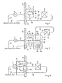
- a high-pressure feed pump 1 is arranged within an internal combustion engine, which is indicated by part of its wall 2, the inside of the wall to the left and the surroundings of the internal combustion engine to the right of this wall.
- a housing 3 is located outside the internal combustion engine, which is located directly on the turn 2, and a heat exchanger 4 some distance away.
- the high-pressure feed pump 1 is connected to the oil sump 6 of the internal combustion engine via a suction line 5 and acts on a pressure reducing element 8, for example a pressure-maintaining valve, which is arranged together with a control valve 9 in the housing 3 via a pressure line 7, the control valve 9 being in one Bypass line 10 to the pressure reduction element 8 is located.
- the control valve 9 has an actuating element 11 which, for. B.
- a supply line 12 to the heat exchanger 4 connects to the pressure reduction element 8, from which a return line 13 leads back to the oil sump 6 via a passage 14 in the wall 2 of the internal combustion engine.
- a short-circuit line 15, which is controlled by a control element 16, is arranged between the feed line 12 and the return line 13.
- FIG. 2 shows the same basic arrangement as in FIG. 1 with the same numbering.
- a further housing or housing part 17 for the control element 16 in the short-circuit line 15 and a third housing or housing part 18 for a lubricating oil filter 19 in the return line 13 are connected to the housing 3 to form a unit.
- the control member 16 in the bypass line 15 between the feed line 12 and return line 13 has an actuating element 20 which, like the actuating element 11, is a solenoid or a. other adjustment device can be.
- the lubricating oil filter 19 is shown without details such as a pressure-controlled bypass line and the like.
- the housing 3 for the pressure reduction element 8 and the control valve 9 is arranged inside the internal combustion engine, that is to the left of the wall 2, and at the same time contains part of the return line 13 from the heat exchanger 4 and the short-circuit line 15 with the control element 16.
- the high-pressure feed pump 1 is flanged directly to the housing 3.
- the housing is arranged on the wall 2 in such a way that the connections to the supply line 12 and the return line 13 and the actuating elements 11 and 20 are sealed off from the interior of the internal combustion engine.
Landscapes
- Engineering & Computer Science (AREA)
- Mechanical Engineering (AREA)
- General Engineering & Computer Science (AREA)
- Physics & Mathematics (AREA)
- Thermal Sciences (AREA)
- Lubrication Of Internal Combustion Engines (AREA)
- Air-Conditioning For Vehicles (AREA)
- Resistance Heating (AREA)
Priority Applications (1)
| Application Number | Priority Date | Filing Date | Title |
|---|---|---|---|
| AT81106307T ATE6236T1 (de) | 1980-11-18 | 1981-08-13 | Heizungssystem in verbindung mit einer brennkraftmaschine. |
Applications Claiming Priority (2)
| Application Number | Priority Date | Filing Date | Title |
|---|---|---|---|
| DE19803043457 DE3043457A1 (de) | 1980-11-18 | 1980-11-18 | Heizungssystem |
| DE3043457 | 1980-11-18 |
Publications (2)
| Publication Number | Publication Date |
|---|---|
| EP0052182A1 true EP0052182A1 (fr) | 1982-05-26 |
| EP0052182B1 EP0052182B1 (fr) | 1984-02-15 |
Family
ID=6117042
Family Applications (1)
| Application Number | Title | Priority Date | Filing Date |
|---|---|---|---|
| EP81106307A Expired EP0052182B1 (fr) | 1980-11-18 | 1981-08-13 | Système de chauffage combiné à un moteur à combustion interne |
Country Status (4)
| Country | Link |
|---|---|
| US (1) | US4407449A (fr) |
| EP (1) | EP0052182B1 (fr) |
| AT (1) | ATE6236T1 (fr) |
| DE (2) | DE3043457A1 (fr) |
Cited By (2)
| Publication number | Priority date | Publication date | Assignee | Title |
|---|---|---|---|---|
| GB2161597B (en) * | 1984-07-02 | 1989-04-19 | Stewart Colin Minerals Ltd | Heating system |
| KR101236222B1 (ko) * | 2007-12-20 | 2013-02-22 | 티센크루프 파우데엠 게엠베하 | 오스테나이트계 내열성 니켈계 합금 |
Families Citing this family (16)
| Publication number | Priority date | Publication date | Assignee | Title |
|---|---|---|---|---|
| US4462386A (en) * | 1983-06-17 | 1984-07-31 | Powell Louis D | Hydraulic friction heater |
| USD297045S (en) | 1985-09-16 | 1988-08-02 | Powell Louis D | Friction furnace |
| US4728029A (en) * | 1986-06-13 | 1988-03-01 | Fmc Corporation | Flameless heater for operator's cab |
| USD300772S (en) | 1986-09-04 | 1989-04-18 | Powell Louis D | Friction furnace |
| DE3817394A1 (de) * | 1988-05-21 | 1988-10-13 | Putsch & Co H | Vorrichtung zum transport und zur verriegelung der platten von filterpressen |
| DE4033551A1 (de) * | 1989-10-23 | 1991-04-25 | Sanden Corp | Klimaanlage fuer fahrzeuge |
| EP0543606B1 (fr) * | 1991-11-18 | 1996-10-16 | Sanden Corporation | Procédé et dispositif de climatisation de voitures |
| US5355939A (en) * | 1991-11-18 | 1994-10-18 | Sanden Corporation | Hydraulically driven vehicular air conditioning system with valve cleaning feature |
| RU2410247C2 (ru) | 2004-02-26 | 2011-01-27 | Вентек, Ллк | Вспомогательная нагревательная система транспортного средства |
| US7523873B1 (en) * | 2004-11-04 | 2009-04-28 | Lopes Walter R | Heating system |
| US8480006B2 (en) | 2006-09-08 | 2013-07-09 | Ventech, Llc | Vehicle supplemental heating system |
| EP2313284B1 (fr) | 2008-07-29 | 2019-10-16 | Ventech, LLC | Système de chauffage supplémentaire incluant un échangeur thermique intégral |
| US9599366B2 (en) * | 2012-03-15 | 2017-03-21 | Steve Hoffert | Flameless heater |
| US9228760B2 (en) | 2012-04-27 | 2016-01-05 | Mac, Inc. | Flameless heating system |
| US10145586B2 (en) | 2015-01-20 | 2018-12-04 | Wacker Neuson Production Americas Llc | Flameless heater |
| AU2021208487A1 (en) * | 2020-01-13 | 2022-09-01 | Other Lab, Llc | Thermal storage system and method |
Citations (2)
| Publication number | Priority date | Publication date | Assignee | Title |
|---|---|---|---|---|
| DE1233204B (de) * | 1965-09-10 | 1967-01-26 | Buckau Wolf Maschf R | Vorrichtung zum Antrieb der zur Schmiermittelversorgung dienenden OElpumpe fuer Brennkraftmaschinen |
| DE2916870A1 (de) * | 1979-04-26 | 1980-11-13 | Kloeckner Humboldt Deutz Ag | Heizung fuer ein land- und/oder wasserfahrzeug |
Family Cites Families (4)
| Publication number | Priority date | Publication date | Assignee | Title |
|---|---|---|---|---|
| GB1191473A (en) * | 1967-08-18 | 1970-05-13 | Stanley Arnold Tippetts | Power Unit. |
| DE2544181A1 (de) * | 1975-10-03 | 1977-04-14 | Howard R Chapman | Zusatzeinrichtung fuer antriebsmaschinen zur erhoehung der leistungsausbeute |
| US4060194A (en) * | 1976-03-08 | 1977-11-29 | Lutz George H | Heating system and element therefor |
| IT1070644B (it) * | 1976-10-26 | 1985-04-02 | Fiat Spa | Perfezionamenti in un impianto pro miscuo per riscaldamento e produzione di energia elettrica tramite motore a combustione interna |
-
1980
- 1980-11-18 DE DE19803043457 patent/DE3043457A1/de not_active Withdrawn
-
1981
- 1981-08-13 EP EP81106307A patent/EP0052182B1/fr not_active Expired
- 1981-08-13 DE DE8181106307T patent/DE3162296D1/de not_active Expired
- 1981-08-13 AT AT81106307T patent/ATE6236T1/de not_active IP Right Cessation
- 1981-10-28 US US06/315,857 patent/US4407449A/en not_active Expired - Fee Related
Patent Citations (2)
| Publication number | Priority date | Publication date | Assignee | Title |
|---|---|---|---|---|
| DE1233204B (de) * | 1965-09-10 | 1967-01-26 | Buckau Wolf Maschf R | Vorrichtung zum Antrieb der zur Schmiermittelversorgung dienenden OElpumpe fuer Brennkraftmaschinen |
| DE2916870A1 (de) * | 1979-04-26 | 1980-11-13 | Kloeckner Humboldt Deutz Ag | Heizung fuer ein land- und/oder wasserfahrzeug |
Cited By (2)
| Publication number | Priority date | Publication date | Assignee | Title |
|---|---|---|---|---|
| GB2161597B (en) * | 1984-07-02 | 1989-04-19 | Stewart Colin Minerals Ltd | Heating system |
| KR101236222B1 (ko) * | 2007-12-20 | 2013-02-22 | 티센크루프 파우데엠 게엠베하 | 오스테나이트계 내열성 니켈계 합금 |
Also Published As
| Publication number | Publication date |
|---|---|
| EP0052182B1 (fr) | 1984-02-15 |
| US4407449A (en) | 1983-10-04 |
| DE3162296D1 (en) | 1984-03-22 |
| ATE6236T1 (de) | 1984-03-15 |
| DE3043457A1 (de) | 1982-07-08 |
Similar Documents
| Publication | Publication Date | Title |
|---|---|---|
| EP0052182A1 (fr) | Système de chauffage combiné à un moteur à combustion interne | |
| DE2435602C3 (de) | Selbsttätige Steuereinrichtung zur Verteilung des Druckmittels auf zwei Hydrauliksysteme | |
| EP0177025A2 (fr) | Système de refroidissement | |
| EP0009564A1 (fr) | Cycle de graissage pour moteur à combustion interne | |
| DD149920A5 (de) | Heizeinrichtung | |
| DE4108915C2 (de) | Hydraulische Einrichtung zur Druckmittelversorgung eines bevorrechtigten Primärlastkreises | |
| DE2914735C2 (de) | Hilfssystem zur Betätigung einer fluidbetriebenen Ruderanlage für Schiffe und Boote | |
| DE19511482A1 (de) | Hydraulische Schaltung | |
| DE19609800C1 (de) | Brennstoffeinspritzsystem für Emulsionsbetrieb | |
| DE102020103723A1 (de) | Hydraulikblock als Redundanz für eine elektronische Bremsvorrichtung eines Fahrzeugs | |
| DE2348572C2 (de) | Nachkühler zur Kühlung und Reinigung von komprimierter Luft | |
| EP0972916B1 (fr) | Dispositif d'entraínement dans un véhicule à moteur | |
| EP1508488B2 (fr) | Installation de production d'air comprimé pour véhicule et méthode pour le faire fonctionner | |
| DE69100220T2 (de) | Verfahren und Vorrichtung zum Filtrieren einer Flüssigkeit. | |
| DE2737938C2 (de) | Antiblockiervorrichtung für eine hydraulische Fahrzeugbremsanlage | |
| DE3022342C2 (de) | Notsteuereinrichtung für eine hydraulische Schiffsruderanlage | |
| EP0644092B1 (fr) | Dispositif de commande | |
| DE3802904A1 (de) | Servounterstuetzte lenkanlage | |
| DE2533164A1 (de) | Hydraulische steuereinrichtung | |
| DE1600728A1 (de) | Ladeventil fuer Drehmomentwandler | |
| EP1527974B1 (fr) | Système de traitement d'air et méthode pour alimenter un système de freinage d'un véhicule utilitaire à moteur avec de l'air comprimé | |
| DE3877608T2 (de) | Kraftstoffregelsystem fuer gasturbinen. | |
| DE3025865A1 (de) | Dieseltreibstoff-steuervorrichtung | |
| DE19600377B4 (de) | Druckgasanlage mit einem Gastrockner | |
| DE3921078A1 (de) | Druckluftbremsanlage mit einer blockierschutzeinrichtung |
Legal Events
| Date | Code | Title | Description |
|---|---|---|---|
| PUAI | Public reference made under article 153(3) epc to a published international application that has entered the european phase |
Free format text: ORIGINAL CODE: 0009012 |
|
| 17P | Request for examination filed |
Effective date: 19811029 |
|
| AK | Designated contracting states |
Designated state(s): AT CH DE FR GB IT SE |
|
| ITF | It: translation for a ep patent filed | ||
| GRAA | (expected) grant |
Free format text: ORIGINAL CODE: 0009210 |
|
| AK | Designated contracting states |
Designated state(s): AT CH DE FR GB IT LI SE |
|
| REF | Corresponds to: |
Ref document number: 6236 Country of ref document: AT Date of ref document: 19840315 Kind code of ref document: T |
|
| REF | Corresponds to: |
Ref document number: 3162296 Country of ref document: DE Date of ref document: 19840322 |
|
| ET | Fr: translation filed | ||
| PGFP | Annual fee paid to national office [announced via postgrant information from national office to epo] |
Ref country code: FR Payment date: 19840716 Year of fee payment: 4 Ref country code: CH Payment date: 19840716 Year of fee payment: 4 |
|
| PGFP | Annual fee paid to national office [announced via postgrant information from national office to epo] |
Ref country code: DE Payment date: 19840906 Year of fee payment: 4 |
|
| PGFP | Annual fee paid to national office [announced via postgrant information from national office to epo] |
Ref country code: SE Payment date: 19840930 Year of fee payment: 4 |
|
| PLBE | No opposition filed within time limit |
Free format text: ORIGINAL CODE: 0009261 |
|
| STAA | Information on the status of an ep patent application or granted ep patent |
Free format text: STATUS: NO OPPOSITION FILED WITHIN TIME LIMIT |
|
| 26N | No opposition filed | ||
| PGFP | Annual fee paid to national office [announced via postgrant information from national office to epo] |
Ref country code: AT Payment date: 19860707 Year of fee payment: 6 |
|
| PG25 | Lapsed in a contracting state [announced via postgrant information from national office to epo] |
Ref country code: GB Free format text: LAPSE BECAUSE OF NON-PAYMENT OF DUE FEES Effective date: 19880813 Ref country code: AT Effective date: 19880813 |
|
| PG25 | Lapsed in a contracting state [announced via postgrant information from national office to epo] |
Ref country code: SE Effective date: 19880814 |
|
| PG25 | Lapsed in a contracting state [announced via postgrant information from national office to epo] |
Ref country code: LI Effective date: 19880831 Ref country code: CH Effective date: 19880831 |
|
| PG25 | Lapsed in a contracting state [announced via postgrant information from national office to epo] |
Ref country code: FR Free format text: LAPSE BECAUSE OF NON-PAYMENT OF DUE FEES Effective date: 19890428 |
|
| REG | Reference to a national code |
Ref country code: CH Ref legal event code: PL |
|
| PG25 | Lapsed in a contracting state [announced via postgrant information from national office to epo] |
Ref country code: DE Effective date: 19890503 |
|
| GBPC | Gb: european patent ceased through non-payment of renewal fee | ||
| REG | Reference to a national code |
Ref country code: FR Ref legal event code: ST |
|
| EUG | Se: european patent has lapsed |
Ref document number: 81106307.2 Effective date: 19890510 |