EP0052182A1 - Heating system in combination with a I.C. Engine - Google Patents
Heating system in combination with a I.C. Engine Download PDFInfo
- Publication number
- EP0052182A1 EP0052182A1 EP81106307A EP81106307A EP0052182A1 EP 0052182 A1 EP0052182 A1 EP 0052182A1 EP 81106307 A EP81106307 A EP 81106307A EP 81106307 A EP81106307 A EP 81106307A EP 0052182 A1 EP0052182 A1 EP 0052182A1
- Authority
- EP
- European Patent Office
- Prior art keywords
- internal combustion
- combustion engine
- pressure
- heating system
- line
- Prior art date
- Legal status (The legal status is an assumption and is not a legal conclusion. Google has not performed a legal analysis and makes no representation as to the accuracy of the status listed.)
- Granted
Links
- 238000010438 heat treatment Methods 0.000 title claims abstract description 17
- 238000002485 combustion reaction Methods 0.000 claims abstract description 41
- 239000003921 oil Substances 0.000 abstract description 9
- 239000010687 lubricating oil Substances 0.000 abstract description 6
- 239000002918 waste heat Substances 0.000 abstract 1
- 230000006378 damage Effects 0.000 description 3
- 208000034656 Contusions Diseases 0.000 description 1
- 208000027418 Wounds and injury Diseases 0.000 description 1
- 230000000694 effects Effects 0.000 description 1
- 230000002349 favourable effect Effects 0.000 description 1
- 208000014674 injury Diseases 0.000 description 1
- 239000003595 mist Substances 0.000 description 1
- 238000007789 sealing Methods 0.000 description 1
- 239000007787 solid Substances 0.000 description 1
Images
Classifications
-
- B—PERFORMING OPERATIONS; TRANSPORTING
- B60—VEHICLES IN GENERAL
- B60H—ARRANGEMENTS OF HEATING, COOLING, VENTILATING OR OTHER AIR-TREATING DEVICES SPECIALLY ADAPTED FOR PASSENGER OR GOODS SPACES OF VEHICLES
- B60H1/00—Heating, cooling or ventilating [HVAC] devices
- B60H1/22—Heating, cooling or ventilating [HVAC] devices the heat being derived otherwise than from the propulsion plant
-
- F—MECHANICAL ENGINEERING; LIGHTING; HEATING; WEAPONS; BLASTING
- F01—MACHINES OR ENGINES IN GENERAL; ENGINE PLANTS IN GENERAL; STEAM ENGINES
- F01M—LUBRICATING OF MACHINES OR ENGINES IN GENERAL; LUBRICATING INTERNAL COMBUSTION ENGINES; CRANKCASE VENTILATING
- F01M5/00—Heating, cooling, or controlling temperature of lubricant; Lubrication means facilitating engine starting
- F01M5/001—Heating
Definitions
- the invention relates to a heating system in connection with an internal combustion engine according to the preamble of the main claim.
- KHD engine F 413 An arrangement of the type mentioned has already been used (KHD engine F 413), in which both the high-pressure feed pump and the pressure reduction element are arranged outside the internal combustion engine and are connected to the inside of the internal combustion engine via external lines.
- the outer course of high-pressure pipelines that are at risk of bruising and pipe connections that are subject to loosening are unsatisfactory and in some cases prone to damage.
- the object of the invention is to improve a heating system in connection with an internal combustion engine, the oil content of which serves as a heating medium and which works with a high-pressure feed pump and a pressure reduction element, in the sense of increased operational safety and a reduced risk of toppling over.
- the solution to this is an internal combustion engine with the features corresponding to the characterizing part of the first claim.
- the high-pressure line from the high-pressure feed pump to the pressure reduction element is located inside the housing of the internal combustion engine, so that any leaks that can predominantly occur in this area cannot cause undesirable external oil ejection and, above all, do not endanger the internal combustion engine through uncontrolled oil loss.
- the arrangement within the oil pan or the engine housing completely eliminates it.
- the combination of the pressure control valve and the control valve arranged in the bypass in a housing also reduces the number of line guides.
- the arrangement of the housing for the pressure reduction element and control valve according to the invention makes it possible to reduce the number of line passages through the housing wall or to do without them entirely, by sealing the housing itself against the wall of the internal combustion engine. is arranged.
- a lubricating oil filter with the pressure holding valve and the control valve in one housing or to connect them directly to their housing and to arrange them directly on the outside of the wall of the internal combustion engine. If necessary.
- control elements for a short-circuit line between the supply line and a return line of the heat exchanger or this short-circuit line itself can also be arranged within this structural unit. As a result, only the low-pressure lines to the heat exchanger, which are connected directly to this compact unit, are arranged outside the internal combustion engine.
- the pressure reduction element and the control valve can be arranged on the wall of the internal combustion engine housing and at the same time connected to the high-pressure feed pump. This means that the high-pressure line can be dispensed with entirely.
- the actuating element of the control valve which can preferably consist of a solenoid, is attached outside a seal of the housing for the pressure reduction element and the control valve with respect to the wall of the internal combustion engine, the corresponding control lines running exclusively outside the internal combustion engine .
- the sensitive control part is advantageously protected from the oil mist and the temperature within the internal combustion engine.
- a high-pressure feed pump 1 is arranged within an internal combustion engine, which is indicated by part of its wall 2, the inside of the wall to the left and the surroundings of the internal combustion engine to the right of this wall.
- a housing 3 is located outside the internal combustion engine, which is located directly on the turn 2, and a heat exchanger 4 some distance away.
- the high-pressure feed pump 1 is connected to the oil sump 6 of the internal combustion engine via a suction line 5 and acts on a pressure reducing element 8, for example a pressure-maintaining valve, which is arranged together with a control valve 9 in the housing 3 via a pressure line 7, the control valve 9 being in one Bypass line 10 to the pressure reduction element 8 is located.
- the control valve 9 has an actuating element 11 which, for. B.
- a supply line 12 to the heat exchanger 4 connects to the pressure reduction element 8, from which a return line 13 leads back to the oil sump 6 via a passage 14 in the wall 2 of the internal combustion engine.
- a short-circuit line 15, which is controlled by a control element 16, is arranged between the feed line 12 and the return line 13.
- FIG. 2 shows the same basic arrangement as in FIG. 1 with the same numbering.
- a further housing or housing part 17 for the control element 16 in the short-circuit line 15 and a third housing or housing part 18 for a lubricating oil filter 19 in the return line 13 are connected to the housing 3 to form a unit.
- the control member 16 in the bypass line 15 between the feed line 12 and return line 13 has an actuating element 20 which, like the actuating element 11, is a solenoid or a. other adjustment device can be.
- the lubricating oil filter 19 is shown without details such as a pressure-controlled bypass line and the like.
- the housing 3 for the pressure reduction element 8 and the control valve 9 is arranged inside the internal combustion engine, that is to the left of the wall 2, and at the same time contains part of the return line 13 from the heat exchanger 4 and the short-circuit line 15 with the control element 16.
- the high-pressure feed pump 1 is flanged directly to the housing 3.
- the housing is arranged on the wall 2 in such a way that the connections to the supply line 12 and the return line 13 and the actuating elements 11 and 20 are sealed off from the interior of the internal combustion engine.
Landscapes
- Engineering & Computer Science (AREA)
- Mechanical Engineering (AREA)
- General Engineering & Computer Science (AREA)
- Physics & Mathematics (AREA)
- Thermal Sciences (AREA)
- Lubrication Of Internal Combustion Engines (AREA)
- Air-Conditioning For Vehicles (AREA)
- Resistance Heating (AREA)
Abstract
Die Erfindung betrifft ein Heizungssystem, in dem Schmieröl einer Brennkraftmaschine einem Wärmetauscher (4) zugeführt wird. Eine im Ölsumpf (6) der Brennkraftmaschine angeordnete Hochdruckförderpumpe (1) dient neben der Förderung zusammen mit einem im oder am Gehäuse (2) der Brennkraftmaschine angeordneten Druckabbauelement (8) einer zusätzlichen Wärmeerzeugung im Schmieröl, das außerdem Abwärme der Brennkraftmaschine dem Wärmetauscher (4) zuführen kann. Der Hochdruckteil des Heizungssystems von der Hochdruckförderpumpe (1) bis zum Druckabbauelement (S) liegt vollständig innerhalb der Brennkraftmaschine.The invention relates to a heating system in which lubricating oil of an internal combustion engine is fed to a heat exchanger (4). A high-pressure feed pump (1) arranged in the oil sump (6) of the internal combustion engine serves, in addition to the delivery together with a pressure reduction element (8) arranged in or on the housing (2) of the internal combustion engine, to generate additional heat in the lubricating oil, which also generates waste heat from the internal combustion engine to the heat exchanger (4). can supply. The high-pressure part of the heating system from the high-pressure feed pump (1) to the pressure reduction element (S) lies entirely within the internal combustion engine.
Description
Die Erfindung betrifft ein Heizungssystem in Verbindung mit einer Brennkraftmaschine entsprechend dem Oberbegriff des Hauptanspruchs.The invention relates to a heating system in connection with an internal combustion engine according to the preamble of the main claim.
Es ist eine Anordnung der genannten Gattung bereits zur Anwendung gekommen (KHD-Motor F 413), bei der sowohl die Hochdruckförderpumpe als auch das Druckabbauelement außerhalb der Brennkraftmaschine angeordnet und über außenliegende Leitungen mit dem Inneren der Brennkraftmaschine verbunden sind. Unbefriedigend und zum Teil schadensanfällig ist dabei vor allem der äußere Verlauf von bruehgezährdeten Hochdruckleitungen und lockagebehafteten Rohrverbindungen.An arrangement of the type mentioned has already been used (KHD engine F 413), in which both the high-pressure feed pump and the pressure reduction element are arranged outside the internal combustion engine and are connected to the inside of the internal combustion engine via external lines. The outer course of high-pressure pipelines that are at risk of bruising and pipe connections that are subject to loosening are unsatisfactory and in some cases prone to damage.
Der Erfindung liegt die Aufgabe zugrunde, ein Heizungssystem in Verbindung mit einer Brennkraftmaschine, deren Ölinhalt als Heizmittel dient, und das mit einer Hochdruckförderpumpe und einem Druckabbauelement arbeitet, im Sinne einer erhöhten Betriebssicherheit und einer herabgesetzten Umfallgefahr zu verbessern.The object of the invention is to improve a heating system in connection with an internal combustion engine, the oil content of which serves as a heating medium and which works with a high-pressure feed pump and a pressure reduction element, in the sense of increased operational safety and a reduced risk of toppling over.
Die Lösung hierfür besteht in einer Brennkraftmaschine mit den Merkmalen entsprechend dem Kennzeichen des ersten Patentanspruchs. In vorteilhafter Weise liegt hierbei die Hochdruckleitung von der Hochdruckförderpumpe zum Druckabbauelement innerhalb des Gehäuses der Brennkraftmaschine, so daß evtl. Undichtigkeiten, die vorwiegend in diesem Bereich auftreten könrien, keinen unerwünschten äußeren Ölauswurf und vor allem keine Gefährdung der Brennkraftmaschine durch unkontrollierten Ölverlust verursachen können. Im Schadensfall geht allein die Heizwirkung der Anordnung verloren, eine Verletzungsgefahr durch einen mit ca. 150 bar austretenden Ölstrahl ist durch die Anordnung innerhalb der Ölwanne bzw. des Motorgehäuses ganz aufgehoben. Die Vereinigung von Druckhalteventil und dazu im Bypaß angeordnetem Steuerventil in einem Gehäuse reduziert darüberhinaus die Zahl der Leitungsführungen.The solution to this is an internal combustion engine with the features corresponding to the characterizing part of the first claim. Advantageously, the high-pressure line from the high-pressure feed pump to the pressure reduction element is located inside the housing of the internal combustion engine, so that any leaks that can predominantly occur in this area cannot cause undesirable external oil ejection and, above all, do not endanger the internal combustion engine through uncontrolled oil loss. In the event of damage, only the heating effect of the arrangement is lost, a risk of injury due to an oil jet escaping at approx. 150 bar, the arrangement within the oil pan or the engine housing completely eliminates it. The combination of the pressure control valve and the control valve arranged in the bypass in a housing also reduces the number of line guides.
Durch die erfindungsgemäße Anordnung des Gehäuses für Druckabbauelement und Steuerventil ist es möglich, die Zahl der-Leitungsdurchtritte durch die Gehäusewand zu reduzieren bzw. auf diese ganz zu.verzichten, indem das Gehäuse selber dichtend gegenüber der Wandung der Brennkraftmaschine ange- . ordnet wird.The arrangement of the housing for the pressure reduction element and control valve according to the invention makes it possible to reduce the number of line passages through the housing wall or to do without them entirely, by sealing the housing itself against the wall of the internal combustion engine. is arranged.
In besonders günstiger erfindungsgemäßer Weise wird vorge- schlagen, ein Schmierölfilter mit dem Druckhalteventil und dem Steuerventil in einem Gehäuse zusammenzufassen bzw. mit deren Gehäuse unmittelbar zu verbinden und unmittelbar außen an der Wandung der Brennkraftmaschine anzuordnen. Ggfs. können hierbei Steuerorgane für eine Kurzschlußleitung zwischen der Vorlaufleitung und einer Rücklaufleitung des Wärmetauschers bzw, diese Kurzschlußleitung selber ebenfalls innerhalb dieser Baueinheit angeordnet sein. Hierdurch sind nur die Niederdruckleitungen zum Wärmetauscher, die unmittelbar an dieses kompakte Aggregat angeschlossen werden, außerhalb der Brennkraftmaschine engeordnet.In a particularly favorable manner according to the invention, it is proposed to combine a lubricating oil filter with the pressure holding valve and the control valve in one housing or to connect them directly to their housing and to arrange them directly on the outside of the wall of the internal combustion engine. If necessary. In this case, control elements for a short-circuit line between the supply line and a return line of the heat exchanger or this short-circuit line itself can also be arranged within this structural unit. As a result, only the low-pressure lines to the heat exchanger, which are connected directly to this compact unit, are arranged outside the internal combustion engine.
In weiterer erfindungsgemäßer Ausgestaltung können das Druckabbauelemellt und das Steuerventil innerhalb, des Gehäuses der Brennkraftmaschine an deren Wandung angeordnet und dabei zugleich mit der Hochdruckförderpumpe verbunden werden. Dadurch kann die Hochdruckleitung vollkommen entfallen.In a further embodiment according to the invention, the pressure reduction element and the control valve can be arranged on the wall of the internal combustion engine housing and at the same time connected to the high-pressure feed pump. This means that the high-pressure line can be dispensed with entirely.
In besonders bevorzugter Ausgestaltung wird bei der zuletzt beschriebenen Ausführung das Betätisungselement des Steuerventils, das vorzugsweise aus einem Hubmagneten bestehen kann, außerhalb einer Abdichtung des Gehäuses für das Druckabbauelement und das Steuerventil gegenüber der Wandung der Brennkraftmaschine angebracht, wobei die entsprechenden Steuerleitungen ausschließlich außerhalb der Brennkraftmaschine verlaufen. Hierdurch wird der empfindliche Steuerungsteil vor dem Ölnebel und der Temperatur innerhalb der Brennkraftmaschine in vorteilhafter Weise geschützt.In a particularly preferred embodiment, in the embodiment described last, the actuating element of the control valve, which can preferably consist of a solenoid, is attached outside a seal of the housing for the pressure reduction element and the control valve with respect to the wall of the internal combustion engine, the corresponding control lines running exclusively outside the internal combustion engine . As a result, the sensitive control part is advantageously protected from the oil mist and the temperature within the internal combustion engine.
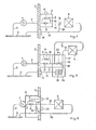
Prinzipskizzen der verschiedenen Anordnungen des Druckabbauelementes, des Steuerventils sowie der übrigen ggfs. damit verbundenen Anlagenteile in Bezug auf die Wandung der Brennkraftmaschine sind in den Zeichungen dargestellt.
- Fig. 1 zeigt Druckabbauelement und Steuerventil in einem außen an der Wandung der Brennkraftmaschine angeordneten Gehäuse,
- Fig. 2 zeigt Gehäuse für Steuerorgane und Schmierölfilter, verbunden mit einem Gehäuse nach Fig. 1,
- Fig. 3 zeigt Druckabbauelement und Steuerventil in einem innen an der Wandung der Brennkraftmaschine angeordneten, mit der Hochdruckförderpumpe verbundenen Gehäuse.
- 1 shows pressure reduction element and control valve in a housing arranged on the outside of the wall of the internal combustion engine,
- 2 shows housings for control elements and lubricating oil filters connected to a housing according to FIG. 1,
- 3 shows the pressure reduction element and control valve in a housing which is arranged on the inside of the wall of the internal combustion engine and is connected to the high-pressure feed pump.
In Fig. 1 ist eine Hochdruckförderpumpe 1 innerhalb einer Brennkraftmaschine angeordnet, die durch einen Teil ihrer Wandung 2 angedeutet ist, wobei links dieser Wrandung das Innere und rechts dieser Wandung die Umgebung der Brennkraftmaschine anzunehmen ist. Außerhalb der Brennkraftmaschine befinden sich ein Gehäuse 3, das unmittelbar an der Wendung 2 angeordnet ist, sowie ein Wärmetauscher 4 in einiger Entfernung davon. Die Hoch- druckförderpumpe 1 ist über eine Saugleitung 5 mit dem Ölsumpf 6 der Brennkraftmaschine verbunden und beaufschlagt über eine Druckleitung 7 ein Drudcabbauelement 8, beispielsweise ein Druckhalteventil, das gemeinsam mit einem Steuerventil 9 in dem Gehäuse 3 angeordnet ist, wobei das Steuerventil 9 in einer Bypaßleitung 10 zum Druckabbauelement 8 liegt. Das Steuerventil 9 weist ein Betätigungselement 11 auf, das z. B. als Hubmagnet, aber auch als pneumatisches oder hydraulisches Stellglied ausgebildet sein kann. An das Druckabbauelement 8 schließt sich eine Vorlaufleitung 12 zum Wärmetauscher 4 an, von dem aus eine Rücklaufleitung 13 über einen Durchtritt 14 in der Wandung 2 der Brennkraftmaschine zurück zum Ölsumpf 6 führt. Zwischen Vorlaufleitung 12 und Rücklaufleitung 13 ist eine Kurzschlußleitung 15 angeordnet, die von einem Steuerorgan 16 beherrscht wird.In Fig. 1, a high-
In Fig. 2 ist bei gleicher Bezifferung im wesentlichen die gleiche Grundanordnung wie in Fig. 1 dargestellt. Ab- weichend sind jedoch mit dem Gehäuse 3 ein weiteres Gehäuse oder Gehäuseteil 17 für das Steuerorgan 16 in der Kurzschlußleitung 15 und ein drittes Gehäuse oder Gehäuseteil 18 für einen Schmierölfilter 19 in der Rücklaufleitung 13 zu einer Einheit verbunden. Das Steuerorgan 16 in der Bypaßleitung 15 zwischen Vorlaufleitung 12 und Rücklaufleit ung 13 weist ein Betätigungselement 20 auf, das genauso wie das Betätigungselement 11 ein Hubmagnet oder eine . sonstige Verstelleinrichtung sein kann. Das Schmierölfilter 19 ist ohne Einzelheiten wie überdruckgesteuerte Umgehungs- leitung und dergl. dargestellt.2 shows the same basic arrangement as in FIG. 1 with the same numbering. In a different way, however, a further housing or
In Fig. 3 ist das Gehäuse 3 für das Druckabbauelement 8 und das Steuerventil 9 innerhalb der Brennkraftmaschine, also links der Wandung 2 angeordnet und enthält zugleich einen Teil der Rücklaufleitung 13 vom Wärmetauscher 4 sowie die Kurzschlußleitung 15 mit dem Steuerorgan 16. Die Hochdruckförderpumpe 1 ist unmittelbar an das Gehäuse 3 angeflanscht. Das Gehäuse ist so an der Wandung 2 angeordnet, daß die Verbindungen mit der Vorlaufleitung 12 und der Rücklaufleitung 13 sowie die Betätigungselemente 11 und 20 gegenüber dem Inneren der Brennkraftmaschine abgedichtet sind. Hiermit befinden sich nur die unter niedrigem Druck stehenden Vorlauf- und Rücklaufleitungen sowie die ggfs. temperaturempfindlichen Steuerorgane außerhalb der Brennkraftmaschine, während alle anderen Teile des Heizungssystems als kompakte Einheit innerhalb derselben angeordnet sind in einer Weise, die die Hochdruckleitung 7 in massive Gehäuse 1, 3 einbezieht.In Fig. 3, the
Claims (5)
dadurch gekennzeichnet, daß das Gehäuse (3) für das Druckabbauelement (8) und das Steuerventil (9) außen an einer Wandung (2) der Brennkraftmaschine angeordnet sind und mit einem Ölfilter (18) und/oder weiteren Steuerorganen (16) für das Heizungssystem, insbesondere für eine Kurzschlußleitung (15) zwischen der Vorlaufleitung (12) und einer Rücklaufleitung (13) des Wärmetauschers (4), unmittelbar verbunden sind.2. Heating system according to claim 1,
characterized in that the housing (3) for the pressure reduction element (8) and the control valve (9) are arranged on the outside of a wall (2) of the internal combustion engine and with an oil filter (18) and / or further control elements (16) for the heating system , in particular for a short-circuit line (15) between the flow line (12) and a return line (13) of the heat exchanger (4), are directly connected.
dadurch gekennzeichnet, daß das Gehäuse (3) für das Druckabbauelement (8) und das Steuerventil (9) innen an einer Wandung (2) der Brennkraftmaschine angeordnet und mit der Hochdruckförderpumpe (1) unmittelbar verbunden sind.4. Heating system according to claim 1,
characterized in that the housing (3) for the pressure reduction element (8) and the control valve (9) are arranged on the inside on a wall (2) of the internal combustion engine and are directly connected to the high-pressure feed pump (1).
Priority Applications (1)
| Application Number | Priority Date | Filing Date | Title |
|---|---|---|---|
| AT81106307T ATE6236T1 (en) | 1980-11-18 | 1981-08-13 | HEATING SYSTEM IN CONNECTION WITH AN INTERNAL ENGINE. |
Applications Claiming Priority (2)
| Application Number | Priority Date | Filing Date | Title |
|---|---|---|---|
| DE19803043457 DE3043457A1 (en) | 1980-11-18 | 1980-11-18 | HEATING SYSTEM |
| DE3043457 | 1980-11-18 |
Publications (2)
| Publication Number | Publication Date |
|---|---|
| EP0052182A1 true EP0052182A1 (en) | 1982-05-26 |
| EP0052182B1 EP0052182B1 (en) | 1984-02-15 |
Family
ID=6117042
Family Applications (1)
| Application Number | Title | Priority Date | Filing Date |
|---|---|---|---|
| EP81106307A Expired EP0052182B1 (en) | 1980-11-18 | 1981-08-13 | Heating system in combination with a i.c. engine |
Country Status (4)
| Country | Link |
|---|---|
| US (1) | US4407449A (en) |
| EP (1) | EP0052182B1 (en) |
| AT (1) | ATE6236T1 (en) |
| DE (2) | DE3043457A1 (en) |
Cited By (2)
| Publication number | Priority date | Publication date | Assignee | Title |
|---|---|---|---|---|
| GB2161597B (en) * | 1984-07-02 | 1989-04-19 | Stewart Colin Minerals Ltd | Heating system |
| KR101236222B1 (en) * | 2007-12-20 | 2013-02-22 | 티센크루프 파우데엠 게엠베하 | Austenitic heat-resistant nickel-base alloy |
Families Citing this family (16)
| Publication number | Priority date | Publication date | Assignee | Title |
|---|---|---|---|---|
| US4462386A (en) * | 1983-06-17 | 1984-07-31 | Powell Louis D | Hydraulic friction heater |
| USD297045S (en) | 1985-09-16 | 1988-08-02 | Powell Louis D | Friction furnace |
| US4728029A (en) * | 1986-06-13 | 1988-03-01 | Fmc Corporation | Flameless heater for operator's cab |
| USD300772S (en) | 1986-09-04 | 1989-04-18 | Powell Louis D | Friction furnace |
| DE3817394A1 (en) * | 1988-05-21 | 1988-10-13 | Putsch & Co H | Apparatus for the transport and latching of the plates of filter presses |
| DE4033551A1 (en) * | 1989-10-23 | 1991-04-25 | Sanden Corp | Air-conditioning system for vehicle with rotary cab - includes radiator valve opened for heating or dehumidification, or both, but closed for air-cooling mode |
| US5355939A (en) * | 1991-11-18 | 1994-10-18 | Sanden Corporation | Hydraulically driven vehicular air conditioning system with valve cleaning feature |
| DE69214604T2 (en) * | 1991-11-18 | 1997-03-13 | Sanden Corp | Method and device for the air conditioning system of a vehicle |
| JP4795332B2 (en) | 2004-02-26 | 2011-10-19 | ベンテック,エルエルシー | Vehicle auxiliary heating system |
| US7523873B1 (en) * | 2004-11-04 | 2009-04-28 | Lopes Walter R | Heating system |
| US8480006B2 (en) | 2006-09-08 | 2013-07-09 | Ventech, Llc | Vehicle supplemental heating system |
| CA2733000C (en) | 2008-07-29 | 2017-09-05 | Ventech, Llc | Supplemental heating system including integral heat exchanger |
| US9599366B2 (en) * | 2012-03-15 | 2017-03-21 | Steve Hoffert | Flameless heater |
| US9228760B2 (en) | 2012-04-27 | 2016-01-05 | Mac, Inc. | Flameless heating system |
| US10145586B2 (en) | 2015-01-20 | 2018-12-04 | Wacker Neuson Production Americas Llc | Flameless heater |
| AU2021208487A1 (en) * | 2020-01-13 | 2022-09-01 | Other Lab, Llc | Thermal storage system and method |
Citations (2)
| Publication number | Priority date | Publication date | Assignee | Title |
|---|---|---|---|---|
| DE1233204B (en) * | 1965-09-10 | 1967-01-26 | Buckau Wolf Maschf R | Device for driving the oil pump for the supply of lubricant for internal combustion engines |
| DE2916870A1 (en) * | 1979-04-26 | 1980-11-13 | Kloeckner Humboldt Deutz Ag | Space heater for heavy land vehicle or boat - uses lubricating oil as heat source with additional power input in heater feed line |
Family Cites Families (4)
| Publication number | Priority date | Publication date | Assignee | Title |
|---|---|---|---|---|
| GB1191473A (en) * | 1967-08-18 | 1970-05-13 | Stanley Arnold Tippetts | Power Unit. |
| DE2544181A1 (en) * | 1975-10-03 | 1977-04-14 | Howard R Chapman | Power unit with auxiliary engine - has main engine coupled to rotary machine using vaporising liquid passed through engine heat exchangers |
| US4060194A (en) * | 1976-03-08 | 1977-11-29 | Lutz George H | Heating system and element therefor |
| IT1070644B (en) * | 1976-10-26 | 1985-04-02 | Fiat Spa | IMPROVEMENTS IN A PRO MISCUOUS SYSTEM FOR HEATING AND ELECTRICITY PRODUCTION THROUGH INTERNAL COMBUSTION ENGINE |
-
1980
- 1980-11-18 DE DE19803043457 patent/DE3043457A1/en not_active Withdrawn
-
1981
- 1981-08-13 AT AT81106307T patent/ATE6236T1/en not_active IP Right Cessation
- 1981-08-13 EP EP81106307A patent/EP0052182B1/en not_active Expired
- 1981-08-13 DE DE8181106307T patent/DE3162296D1/en not_active Expired
- 1981-10-28 US US06/315,857 patent/US4407449A/en not_active Expired - Fee Related
Patent Citations (2)
| Publication number | Priority date | Publication date | Assignee | Title |
|---|---|---|---|---|
| DE1233204B (en) * | 1965-09-10 | 1967-01-26 | Buckau Wolf Maschf R | Device for driving the oil pump for the supply of lubricant for internal combustion engines |
| DE2916870A1 (en) * | 1979-04-26 | 1980-11-13 | Kloeckner Humboldt Deutz Ag | Space heater for heavy land vehicle or boat - uses lubricating oil as heat source with additional power input in heater feed line |
Cited By (2)
| Publication number | Priority date | Publication date | Assignee | Title |
|---|---|---|---|---|
| GB2161597B (en) * | 1984-07-02 | 1989-04-19 | Stewart Colin Minerals Ltd | Heating system |
| KR101236222B1 (en) * | 2007-12-20 | 2013-02-22 | 티센크루프 파우데엠 게엠베하 | Austenitic heat-resistant nickel-base alloy |
Also Published As
| Publication number | Publication date |
|---|---|
| ATE6236T1 (en) | 1984-03-15 |
| DE3043457A1 (en) | 1982-07-08 |
| DE3162296D1 (en) | 1984-03-22 |
| EP0052182B1 (en) | 1984-02-15 |
| US4407449A (en) | 1983-10-04 |
Similar Documents
| Publication | Publication Date | Title |
|---|---|---|
| EP0052182A1 (en) | Heating system in combination with a I.C. Engine | |
| DE2435602C3 (en) | Automatic control device for distributing the pressure medium to two hydraulic systems | |
| DE60117927T2 (en) | Detecting fuel leaks | |
| EP0177025A2 (en) | Cooling system | |
| DD149920A5 (en) | HEATING DEVICE | |
| DE4108915C2 (en) | Hydraulic device for supplying pressure medium to a privileged primary load circuit | |
| DE2914735C2 (en) | Auxiliary system for operating a fluid-operated steering system for ships and boats | |
| DE19609800C1 (en) | Injection system for internal combustion engine supplying e.g. pure diesel or water emulsion | |
| DE19511482A1 (en) | Hydraulic circuit | |
| DE102020103723A1 (en) | Hydraulic block as redundancy for an electronic braking device of a vehicle | |
| DE2348572C2 (en) | Aftercooler for cooling and cleaning compressed air | |
| EP0972916B1 (en) | Drive system in a motor vehicle | |
| DE69314592T2 (en) | Fuel supply system for internal combustion engines | |
| EP1508488B2 (en) | Installation of compressed air production for a vehicle and method of operating the same | |
| DE60007181T2 (en) | Fuel circuit with protected main flow filter | |
| DE69100220T2 (en) | Method and device for filtering a liquid. | |
| DE2737938C2 (en) | Anti-lock device for a hydraulic vehicle brake system | |
| DE1932600A1 (en) | Load-dependent control of the start of injection in injection pumps with electromagnetically operated control devices | |
| DE3022342C2 (en) | Emergency control device for a hydraulic ship's rudder system | |
| EP0644092B1 (en) | Control device | |
| DE2533164A1 (en) | HYDRAULIC CONTROL DEVICE | |
| DE3877608T2 (en) | FUEL CONTROL SYSTEM FOR GAS TURBINES. | |
| DE3025865A1 (en) | FUEL CONTROL DEVICE | |
| DE19600377B4 (en) | Compressed gas system with a gas dryer | |
| DE3921078A1 (en) | COMPRESSED AIR BRAKE SYSTEM WITH AN ANTI-BLOCKING DEVICE |
Legal Events
| Date | Code | Title | Description |
|---|---|---|---|
| PUAI | Public reference made under article 153(3) epc to a published international application that has entered the european phase |
Free format text: ORIGINAL CODE: 0009012 |
|
| 17P | Request for examination filed |
Effective date: 19811029 |
|
| AK | Designated contracting states |
Designated state(s): AT CH DE FR GB IT SE |
|
| ITF | It: translation for a ep patent filed | ||
| GRAA | (expected) grant |
Free format text: ORIGINAL CODE: 0009210 |
|
| AK | Designated contracting states |
Designated state(s): AT CH DE FR GB IT LI SE |
|
| REF | Corresponds to: |
Ref document number: 6236 Country of ref document: AT Date of ref document: 19840315 Kind code of ref document: T |
|
| REF | Corresponds to: |
Ref document number: 3162296 Country of ref document: DE Date of ref document: 19840322 |
|
| ET | Fr: translation filed | ||
| PGFP | Annual fee paid to national office [announced via postgrant information from national office to epo] |
Ref country code: FR Payment date: 19840716 Year of fee payment: 4 Ref country code: CH Payment date: 19840716 Year of fee payment: 4 |
|
| PGFP | Annual fee paid to national office [announced via postgrant information from national office to epo] |
Ref country code: DE Payment date: 19840906 Year of fee payment: 4 |
|
| PGFP | Annual fee paid to national office [announced via postgrant information from national office to epo] |
Ref country code: SE Payment date: 19840930 Year of fee payment: 4 |
|
| PLBE | No opposition filed within time limit |
Free format text: ORIGINAL CODE: 0009261 |
|
| STAA | Information on the status of an ep patent application or granted ep patent |
Free format text: STATUS: NO OPPOSITION FILED WITHIN TIME LIMIT |
|
| 26N | No opposition filed | ||
| PGFP | Annual fee paid to national office [announced via postgrant information from national office to epo] |
Ref country code: AT Payment date: 19860707 Year of fee payment: 6 |
|
| PG25 | Lapsed in a contracting state [announced via postgrant information from national office to epo] |
Ref country code: GB Free format text: LAPSE BECAUSE OF NON-PAYMENT OF DUE FEES Effective date: 19880813 Ref country code: AT Effective date: 19880813 |
|
| PG25 | Lapsed in a contracting state [announced via postgrant information from national office to epo] |
Ref country code: SE Effective date: 19880814 |
|
| PG25 | Lapsed in a contracting state [announced via postgrant information from national office to epo] |
Ref country code: LI Effective date: 19880831 Ref country code: CH Effective date: 19880831 |
|
| PG25 | Lapsed in a contracting state [announced via postgrant information from national office to epo] |
Ref country code: FR Free format text: LAPSE BECAUSE OF NON-PAYMENT OF DUE FEES Effective date: 19890428 |
|
| REG | Reference to a national code |
Ref country code: CH Ref legal event code: PL |
|
| PG25 | Lapsed in a contracting state [announced via postgrant information from national office to epo] |
Ref country code: DE Effective date: 19890503 |
|
| GBPC | Gb: european patent ceased through non-payment of renewal fee | ||
| REG | Reference to a national code |
Ref country code: FR Ref legal event code: ST |
|
| EUG | Se: european patent has lapsed |
Ref document number: 81106307.2 Effective date: 19890510 |