EP1508488B2 - Installation de production d'air comprimé pour véhicule et méthode pour le faire fonctionner - Google Patents
Installation de production d'air comprimé pour véhicule et méthode pour le faire fonctionner Download PDFInfo
- Publication number
- EP1508488B2 EP1508488B2 EP04019344A EP04019344A EP1508488B2 EP 1508488 B2 EP1508488 B2 EP 1508488B2 EP 04019344 A EP04019344 A EP 04019344A EP 04019344 A EP04019344 A EP 04019344A EP 1508488 B2 EP1508488 B2 EP 1508488B2
- Authority
- EP
- European Patent Office
- Prior art keywords
- valve
- control group
- circuits
- control
- valves
- Prior art date
- Legal status (The legal status is an assumption and is not a legal conclusion. Google has not performed a legal analysis and makes no representation as to the accuracy of the status listed.)
- Active
Links
- 238000000034 method Methods 0.000 title claims description 9
- 238000009434 installation Methods 0.000 title 1
- 238000011144 upstream manufacturing Methods 0.000 claims description 7
- 238000005086 pumping Methods 0.000 claims 5
- 238000009423 ventilation Methods 0.000 description 25
- 230000008929 regeneration Effects 0.000 description 17
- 238000011069 regeneration method Methods 0.000 description 17
- 230000000903 blocking effect Effects 0.000 description 9
- 239000000725 suspension Substances 0.000 description 8
- 238000010586 diagram Methods 0.000 description 7
- 230000015572 biosynthetic process Effects 0.000 description 2
- 230000007423 decrease Effects 0.000 description 2
- 230000007547 defect Effects 0.000 description 2
- 238000005516 engineering process Methods 0.000 description 2
- 244000037459 secondary consumers Species 0.000 description 2
- 230000002411 adverse Effects 0.000 description 1
- 238000004378 air conditioning Methods 0.000 description 1
- 238000010276 construction Methods 0.000 description 1
- 230000001419 dependent effect Effects 0.000 description 1
- 238000001514 detection method Methods 0.000 description 1
- 230000001627 detrimental effect Effects 0.000 description 1
- 230000000694 effects Effects 0.000 description 1
- 210000003746 feather Anatomy 0.000 description 1
- 238000012544 monitoring process Methods 0.000 description 1
- 238000002360 preparation method Methods 0.000 description 1
- 230000001960 triggered effect Effects 0.000 description 1
Images


Classifications
-
- B—PERFORMING OPERATIONS; TRANSPORTING
- B60—VEHICLES IN GENERAL
- B60T—VEHICLE BRAKE CONTROL SYSTEMS OR PARTS THEREOF; BRAKE CONTROL SYSTEMS OR PARTS THEREOF, IN GENERAL; ARRANGEMENT OF BRAKING ELEMENTS ON VEHICLES IN GENERAL; PORTABLE DEVICES FOR PREVENTING UNWANTED MOVEMENT OF VEHICLES; VEHICLE MODIFICATIONS TO FACILITATE COOLING OF BRAKES
- B60T17/00—Component parts, details, or accessories of power brake systems not covered by groups B60T8/00, B60T13/00 or B60T15/00, or presenting other characteristic features
- B60T17/02—Arrangements of pumps or compressors, or control devices therefor
Definitions
- the invention relates to a method for operating a compressed air procurement system of a motor vehicle and compressed air processing device with the features specified in the preambles of claims 1 and 5.
- a compressed air procurement system has a compressed air treatment device and a compressor and the individual consumer circuits associated reservoir for compressed air of certain pressure level.
- the compressed air treatment device has a pressure regulator, usually also an air dryer, a multi-circuit protection valve and control electronics. Depending on the embodiment, these parts are joined together to form a common structural unit.
- Such a common structural unit can, for example, be connected downstream of the compressor of a compressed air procurement device as a compressed air treatment device.
- a compressed air treatment device of the type in question is from the DE 44 21 575 C2 known.
- a pressure regulator, an air dryer, a multi-circuit protection valve and control electronics are assembled to form a common unit.
- the individual consumer circuits associated mechanical-pneumatic valves, in particular overflow valves, pressure limiters, switching valves and / or check valves and the like.
- the signals of the control electronics are fed. All circles are treated equally or equally.
- the circuits can be protected by the overflow valves with limited backflow. In this case, each solenoid valve is assigned to each overflow valve of each circuit.
- the solenoid valve is open when not energized, ie the spring chamber of the overflow valve is connected to the flow chamber.
- the overflow valve has a comparatively increased opening pressure.
- the solenoid valve switches over and vents the spring chamber. This is a locking the overflow valves and a targeted opening of the overflow valves by releasing the normal function of a spill valve with its two active surfaces possible.
- the protection can also be done by pilot operated check valves, which can be pushed open by a solenoid valve to be switched via an actuating piston.
- the air suspension of the vehicle may be connected.
- an overflow valve with limited backflow is connected without pilot control.
- the overflow valve is thus part of the multi-circuit protection valve. In its open position it allows an exchange of air with the other circles.
- the air suspension may also be connected to the circle IV, which is constructed in accordance with the structure of the circles I to III.
- the circle V is also used for regeneration.
- Control electronics control all circuits together, depending on the air consumption in one of the circuits.
- the pressure regulator with the associated outlet valve is controlled in the same way, regardless of the circle in which an air consumption has occurred. This is harmless for the life of the compressor, as long as the supply pressure in the circle V has a pressure level corresponding to the pressure level of the other circles.
- a similar compressed air treatment device of a compressed air procurement system is also from the DE 195 44 621 C1 known.
- a common housing which may also be formed divided, a pressure regulator, an air dryer, a multi-circuit protection valve and an electronic control unit is housed with their corresponding elements.
- the multi-circuit protection valve is designed and arranged for all circuits that branch off from the housing.
- Each circuit has an overflow valve with limited backflow.
- the overflow valves are open so that an air exchange is possible.
- the air suspension can be connected.
- the circle V is also used for the regeneration of the air dryer.
- About the air consumption of the pressure regulator and thus the idle / load cycle of the compressor is controlled. There are the same disadvantages as described above.
- Another compressed air treatment device is from the DE 197 00 243 C1 known.
- a pressure relief valve upstream or downstream of an overflow valve, which is pilot-controlled via a solenoid valve.
- the pressure is controlled jointly via the control electronics for all circuits.
- the DE 195 15 895 A1 shows a compressed air treatment device with a pressure regulator, an air dryer and an integrated multi-circuit protection valve.
- the air dryer is followed by the usual check valve on which the central ventilation begins, via which the overflow valves of the individual Circles are supplied with compressed air.
- pilot valves are connected upstream of the overflow valves.
- Solenoid valves can also be used to connect shut-off valves connected downstream of the overflow valves.
- the overflow valves and the solenoid valves can be replaced by a control electronics directly controllable check valves. In most circles, the output side pressures are detected by pressure sensors whose signals are routed to the control electronics.
- the initial filling, the sequence of filling the circuits, the setting of different operating pressures, the compensation of different compressed air consumption in the circuits and the refilling of the circuits can be varied within wide limits.
- the operation of the compressor can be controlled.
- the kinetic energy of the vehicle can be used in push mode to fill a circuit to a higher pressure level than the operating pressure of this circuit.
- By air exchange with this circle another circle can be operated.
- the individual control also adversely increases the switching frequency of the pressure regulator and the number of circuits of the load / idle cycle and thus the life of the compressor.
- failure or a defect in the power supply of the control electronics results in a total failure of the compressed air treatment device and the compressed air procurement system. If an air exchange between individual or all circuits is intended, then the relevant check valves of the circles must be opened for this purpose. But then stored compressed air is lost over the check valve before the central ventilation bridging line with throttle, at least during an idle phase, although at this time a regeneration is not intended.
- Another disadvantage is that in case of power failure, either as a result of an incoming defect or by switching off the ignition of the motor vehicle, all connected circuits are emptied to the closing pressure of the overflow valves. The necessary refilling requires additional compressor work.
- the invention has for its object to provide a method for operating a compressed air procurement plant and such a compressed air procurement plant, which has circles with different pressure levels and in which the compressor does not have to promote against the maximum pressure in air consumption in circles with non-maximum pressure level.
- the number of electrically generated by the control electronics circuits for the overflow valves, check valves and the like should be kept as low as possible to keep the life of the compressed air supply system and the compressed air conditioning device high.
- the new Invention to form at the described location at least two control groups, which have different effects on the control of the pressure regulator and then the compressor.
- the one control group includes in any case the circle in which the maximum pressure level must be kept in stock.
- This circuit may in particular be the supply of an air suspension of the motor vehicle, wherein the pressure level may be, in particular, of the order of 12 to 15 bar. It is readily possible that this control group has only this one circle V.
- the other control group comprises the service brake circuits of circuits I and II, the circuit III to supply the trailer brake and the parking brake and the circuit IV to supply the auxiliary consumers.
- a pressure of 12 bar may be desired or fixed.
- the circle III can have 8.5 bar.
- the secondary consumers on the circle IV may require, for example, 10 bar.
- a subdivision of the individual circles into two control groups is sufficient, as described. However, it is also possible to form more than two control groups in order to get a more detailed subdivision in certain areas. The purpose of the formation of these control groups is to operate the compressor differently, depending on the, in which the circles of the control groups air consumption. So it is sufficient in many cases, the maximum pressure of z. B.
- the purpose of this mode of operation is also to reduce the number of circuits of the solenoid valves, overflow valves or other actuators in order to promote the longevity of the system. A multiple switching back and forth of solenoid valves, check valves and the like for approximately reaching a corresponding pressure level is thus avoided. It is also intended to reduce the number of circuits triggered by the control electronics, ie to leave in the individual control groups, in particular in the control group, which includes the minimum pressure level, reliably operating mechanical-pneumatic elements or to arrange without requiring electronic switching pulses to allow a distribution of compressed air at different pressure levels on the individual circuits.
- the mechanical-pneumatic elements provide a useful function even in case of failure or failure of the power supply.
- a regeneration valve In order to allow an exchange of air between a plurality of groups combined into a group without loss of compressed air, it is significant that in the check valve bridging the bypass before the central ventilation, a regeneration valve is provided.
- the regeneration valve should de-energize a blocking position and be transferred only for purposes of regeneration in a through position. Thus, it is possible that regeneration takes place only when needed by the control electronics upon request.
- the desired air exchange between circles of a group is not necessarily associated with a loss of air into the atmosphere. In the event of a power failure, in particular when the vehicle is parked, an air loss up to the closing pressure of the overflow valves and the comparatively increased energy requirement when the circuits are refilled are avoided.
- the maximum pressures at the maximum pressure level control group and the minimum pressure level control group at the outputs to individual circuit reservoirs are respectively measured and used to control the compressor's duty and idle cycle.
- an approved air exchange between the circles of a steering group is used advantageously.
- the construction cost is reduced by no longer each circuit must be provided with a pressure sensor.
- the distribution of the compressed air conveyed by the compressor in the load phase to the individual circuits takes place using mechanical-pneumatic valves, in particular overflow valves, pressure limiters, switching valves and / or check valves and the like.
- mechanical-pneumatic valves can do with few switching pulses and have great reliability and longevity.
- Air exchange between the control group comprising the maximum pressure altitude and the control group comprising the minimum pressure altitude is prevented. So it is not intended to allow an exchange of air between the circle with the maximum pressure level and the other circles. Such a control would simulate air consumption in the circuit with the maximum pressure level and in turn force it to operate the compressor again against the maximum pressure level.
- the compressed air preparation device is part of it a compressed air supply system, which in turn has a compressor.
- the compressed air processing device has a pressure regulator, an air dryer, a multi-circuit protection valve and control electronics, which can be combined in a common unit.
- the compressed air treatment device may also have a regeneration valve.
- mechanical-pneumatic valves assigned to the individual circuits in particular overflow valves with limited return flow, pressure limiters, switching valves and / or non-return valves or the like, are provided. This is achieved by the features of claim 5 according to the invention.
- the circuits are subdivided into at least two control groups by one or more elements, of which one control group comprises or has the circle with the maximum pressure level, while the other control group comprises or has the circle with the minimum pressure level.
- the compressor is switched between idle phase and load phase via the pressure regulator and an associated exhaust valve of a signal generated by the control electronics according to the air consumption in the two control groups formed. Since the predominant air consumption occurs during travel in circuits I and II, which supply the service brake, the compressor can be operated with a cut-off pressure at the end of the load phase, which is lower than the maximum pressure of the air spring system. This protects the compressor and improves the longevity of the elements of the system. Of course, at some point, the reservoir must be filled with the maximum pressure level or refilled.
- the compressor is typically operated at a lower pressure level and is adapted to the compressed air consumption in the control group of circuits which do not have the maximum pressure level.
- the processing device is equipped with one or more elements in one or more of the circles so that control technology at least two control groups are achieved in a very different manner.
- a comparatively simple embodiment arises when the control-technical subdivision effecting elements in the supply line of the circle V, ie the circle with the maximum pressure level, a spill valve with limited backflow and a check valve.
- the order of these two valves in the supply line is arbitrary.
- the check valve is installed in such a way that it prevents in any case an exchange of air with circuits of the other control group.
- the check valve stores the once reached maximum pressure level in the associated reservoir reliably, so that the air stored there is used exclusively for this purpose, but not for air exchange.
- a check valve in the supply line, which branches off from the central ventilation after the check valve, which has a passage position and a blocking position, for example, via an electrically controllable solenoid valve is controlled.
- a direct control of the check valve via the control electronics is possible.
- This check valve has expediently also a mechanical spring, which ensures that the check valve in the de-energized state assumes the blocking position.
- a slightly different group of solutions provide as an element for the formation of the two control groups as it were a switch or a switching valve, which is immediately downstream of the provided there check valve in the central ventilation.
- This switching valve has two positions, one of which is taken in turn due to the force of a mechanical spring, while the other can be pre-controlled for example by a solenoid valve or directly controlled by the control electronics.
- the switching range of the pressure regulator or the compressor is also selected or specified differently depending on the requirements in one control group or the other control group.
- the measures required for this purpose can be included in the control electronics. This results in this possibility the particular advantage that in the control group, which operates only the circuit V at the maximum pressure level, all mechanical-pneumatic valves, such as overflow valves, check valves and the like, and also electrically switchable valves, e.g. Solenoid valves, can get lost.
- the switching valve or the switch so that in one position only the control group with the maximum pressure level and in the other position both control groups or all control groups are served or supplied.
- the supply line for the circuit V must be provided with corresponding elements, in particular with a spill valve with limited backflow and a check valve or a spill valve without backflow.
- the control group which does not include the maximum pressure, can otherwise be formed largely unchanged compared to the prior art, ie it can overflow valves, pressure limiters, switching valves, solenoid valve pilot operated switching valves and the like application Find.
- the present invention is also completely independent of a regeneration feasible, ie, the controller can also be designed or tuned to a required regeneration of the air dryer and used.
- Another possibility for forming two or more control groups is to pre-allocate switchable overflow valves of circuits I and II, for example, a common shut-off valve.
- This check valve has a passage position and a blocking position, is acted upon by a mechanical spring in the passage position and can, for. B. are electrically controlled by a solenoid valve to take the locked position. This is done in conjunction with an overflow valve and a check valve in the circle, which has the maximum pressure level.
- the check valve described above can also be replaced by a pressure limiter, which is connected upstream of the controllable overflow valves of circuits I and II. As soon as the set pressure at the pressure limiter is reached or exceeded, not only the circles I and II, but also the circles III and IV are properly filled. By detecting the pressure on the output side of the circuit V, a signal for the circuit of the pressure regulator is generated or suppressed via the control electronics, which initiates the idling phase of the compressor.
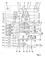
- FIG. 1 The circuit diagram shown, the essential elements are illustrated by symbols. It is a compressed air processing device 1 illustrated by a dash-dotted lines as a common unit, which has the various elements within a housing.
- the outline of the compressed air treatment device 1 can also be regarded as a housing.
- connection 2 is provided, to which a line 3 is introduced, which emanates from a compressor 4.
- the line 3 continues within a line 5 in the compressed air processing device 1, which leads on the one hand to an air dryer 6.
- a line 7 leads to a check valve 8, which in the usual way separates the part of the compressed air treatment device before the check valve 8 from the subsequent central ventilation 9.
- the central ventilation 9 can also be regarded as a common inflow space via which the individual circuits I to V are supplied.
- a line 10 leads to a safety valve 11, which is connected on the output side to a vent opening 12. It is a pressure regulator 13 is provided which has as recognizable a blocking position and a passage position and is acted upon by the force of a spring in the blocking position, while on the other hand, is switched by a solenoid valve in the passage position corresponding to the idling phase.
- a control valve 14 is provided, which switches the compressor 4 via a line 15. Via the line 15, a clutch can be switched on the compressor 4 or, for example, an air promotion in the compressor 4 are influenced.
- the control valve 14 is supplied from the central ventilation 9 via a line 16 with compressed air.
- a supply line 17 leads to a controlled overflow valve 18, which is assigned to the circuit I.
- the supply line 19 is provided, which ultimately leads via a connection and a corresponding line to a reservoir 20 of the circuit I.
- the circle II is formed accordingly.
- the reservoir 20 and 24 are assigned to the two service brake circuits and can be designed or determined for a pressure of 12 bar.
- the controlled overflow valve 18 is initially constructed like any overflow valve with limited backflow, ie, it has on the inflow side a first effective area and downstream a second effective area, so that the usual hysteresis arises between the opening and closing pressure.
- the overflow valve 18 also has a third and a fourth effective area, wherein the third active surface is pneumatically controlled by a solenoid valve 25 and serves to open the overflow valve 18.
- the fourth active surface is controlled by a solenoid valve 26 and serves to reach the closed position of the overflow valve 18.
- the solenoid valves 25 and 26 also control the spill valve 22 with its third and fourth effective area accordingly.
- a pressure sensor 28 detects the pressure in the supply line 19 and thus in the reservoir 20 and outputs a corresponding voltage signal via a line not shown to a control electronics 29. It is understood that from the control electronics 29 and corresponding electrical control lines not shown to the other elements, For example, also to the solenoid valves 25 and 26 are performed.
- solenoid valve 30 is provided which, as shown, has the two switching positions, is controlled by the control electronics 29 and in turn controls the pressure regulator 13 as well as the control valve 14 pneumatically.
- the regeneration valve 31 is arranged in a bypass line 32, which bridges the check valve 8 and thus a return flow between the central ventilation 9 and the line 7.
- the regeneration valve 31 is also actuated via the solenoid valve 25 backward through the air dryer 6 allows.
- the circle III has a supply line 33, which starts from the central ventilation 9 and leads to an overflow valve 34, which, however, has only three active surfaces.
- a solenoid valve 35 is provided to set an open position of the overflow valve 34.
- a supply line 36 leads to the circle III, which is shown here with the saving of a reservoir.
- a pressure limiter 37 is included, which passes on reaching a set pressure, for example, 8.5 bar, in the closed position.
- the trailer is supplied with compressed air.
- From the supply line 36 branches off a supply line 38, which is assigned to the supply of the handbrake.
- a check valve 39 is installed in the direction shown.
- a safety valve 40 leads via a line 41 to a vent port 42.
- a supply line 43 which leads to an overflow valve 44 with downstream pressure limiter 45.
- a supply line 46 is associated with the circle IV, may be connected to the auxiliary consumers, which require a pressure of 10 bar for their operation.
- the overflow valves 18, 22, 34 and 44 are components of a multi-circuit protection valve 47 and thus a first control group 48, which summarizes the circles I to IV. It can be seen that the two service brake circuits I and II are supplied with the highest pressure within the control group 48, namely 12 bar.
- the circle V forms a second control group 49.
- a supply line 50 branches off from the central ventilation 9, which leads to an overflow valve 51 and a downstream check valve 52. It continues in a supply line 53, which ultimately leads to a reservoir 54 of the circle V.
- the circuit V is used to supply an air spring system of the motor vehicle and may be set to a supply pressure of 15 bar.
- the second control group 49 is in any case the group that comprises or has the maximum pressure compared to all occurring supply pressures.
- the output side pressures of the various circuits are monitored by pressure sensors.
- a pressure sensor 55 is provided and connected in the appropriate manner.
- a pressure sensor 56 monitors the output pressure in the supply line 36 of the circle III.
- a pressure sensor 57 monitors the pressure in the supply line 53 and the reservoir 54 of the circle V. All pressure sensors 28, 55, 56, 57 are connected by electrical lines to the control electronics 29, so that the pressure corresponding voltage signals are processed.
- the two control groups 48 and 49 are formed.
- the elements of the multi-circuit protection valve 47 are concentrated on the group 48.
- the overflow valve 51 and the check valve 52 in the supply of the circuit V is not part of the multi-circuit protection valve. Rather, the check valve 52 prevents backflow into the circuits of the control group 48.
- the elements are in the illustrated positions.
- the compressor 4 via the lines 3 and 5 promotes compressed air, dried by the air dryer 6 in the line 7 and the check valve 8 in the central ventilation 9 and thus before the closed spill valves of the various circles I to V arrives.
- the overflow valves 18 and 22 are transferred to the open position.
- the pressure in the reservoirs 20 and 24 has risen to, for example, 7 bar, which is reported by the pressure sensors 28 and 55 to the control electronics 29.
- the solenoid valve 25 is turned off and the solenoid valve 35 is driven.
- the overflow valves 18 and 22 are transferred to the closed position. This is done by means of a switching pulse via the solenoid valve 26 and the fourth effective surface of the overflow valves 18 and 22. It is followed by a further pressure increase in the container 54, which can be completed by reaching the intended pressure of 15 bar for the air suspension. This is reported to the control electronics 29 via the sensor 57. This is followed by switching of the solenoid valve 30. As a result, the pressure regulator 13 is transferred to its passage position, so that the idle phase is turned on and the compressor 4 promotes through the vent port 12 into the atmosphere. In parallel, the control valve 14 is switched so that a pressure pulse interrupts the promotion of the compressor 4. The solenoid valve 26 is turned off, so that the spill valves can return to their normal open position and an air exchange between the circles I to IV is possible.
- a regeneration of the air dryer 6 take place. This is done by the solenoid valve 25 by the regeneration valve 31 is transferred to the open position and compressed air from the circuits I and II is used for regeneration.
- the journey begins.
- driving occurs in the sequence of braking compressed air consumption in the circles I and II, so that the pressure in the reservoirs 20 and 24 decreases, while in the other circles, especially in the circle V, no compressed air consumption may occur.
- the solenoid valve 30 is switched again.
- the pressure regulator 13 and the control valve 14 change their positions again, so that the compressor 4 in turn promotes compressed air, which passes through the check valve 8 in the central ventilation 9.
- the compressed air passes through the overflow valves 18 and 22, which are in their normal open position, into the reservoir 20 and 24 until there the intended pressure of 12 bar is reached again.
- the pressure sensors 28 and 55 monitor these pressures and report reaching the control electronics 29, so that in the sequence of the pressure regulator 13 and the control valve 14 are switched again, so that the compressor 4 stops its promotion.
- the compressor 4 must promote with a maximum of 12 bar. The compressor 4 is protected during these phases, which manifests itself in a long life.
- Fig. 2 shown compressed air treatment plant is similar in many areas as the system according to Fig. 1 trained, which is why the local description can be referenced. All details regarding the control group 48 are unchanged. Again, only the circle V is detected in the control group 49.
- a check valve 58 is arranged here, which, as can be seen, has a blocking position and a passage position. In de-energized state, the blocking position is switched by a spring 59.
- the solenoid valve 26 not only switches the two overflow valves 18 and 22 in the closed position, but also switches the check valve 58 in the passage position.
- a separate electrically controllable solenoid valve in the supply line 50, 53 may be provided, which is controlled directly via the control electronics 29.
- the check valve 58 also fulfills the function of the check valve 52 of the system according to Fig. 1 That is, in the blocking position, a backflow and an exchange of compressed air is prevented to the overflow valves of the control group 48.
- a switching valve 60 which is located at the beginning of the central ventilation 9 immediately after the check valve 8.
- the changeover valve 60 has two positions by once connecting the control group 48 and completing the control group 49 and vice versa. It suffices here the arrangement of the solenoid valves 30, 25 and 26 and the pressure sensors 28, 55 and 57.
- the overflow valves 18 and 22 have here only three active surfaces.
- the pressure limiter 37 is here jointly assigned to the circles III and IV and arranged in front of the respective overflow valves 34 and 44.
- no switching element is arranged in the supply line 50, 53 which has from the central ventilation 9 via a line 61 connection in the relevant position of the change-over valve 60 to the central ventilation 9, no switching element is arranged.
- a line 62 leads from the switching valve 60 to the elements of the circles I to IV and the multi-circuit protection valve 47. It can be seen how switching the changeover valve 60, which takes place via the solenoid valve 26, but also directly from the control electronics 29 can be operated, either only the control group 48 or the control group 49. Accordingly, the load running phase of the compressor 4 is set and performed. Since it is also to be expected here with the essential compressed air consumption in the area of circles I and II, the compressor 4 is operated at this comparatively lower pressure level. Only now and then must the container 54 be filled with the maximum pressure.
- Fig. 4 connects to the embodiments described above.
- a switching valve 63 is provided at the beginning of the central ventilation.
- the switching valve 63 has two positions, as shown. In one position only the line 61 is operated, in the other position, the lines 61 and 62 are connected simultaneously. In this case, in the supply line 50, 53 of the circuit V, the arrangement of the overflow valve 51 and the check valve 52 is required.
- the check valve 52 is arranged upstream of the overflow valve 51 here. In this way, again, the two control groups 48 and 49 are formed. Again, the control group 48, the four circles I, II, III and IV, while the second control group also has only the circle V.
- control group 48 is designed to omit the supply of the maximum pressure and to be directed substantially to the highest occurring pressure within the circles grouped together by the control group 48, while the second control group 49 in any case comprises the circle which is the maximum Pressure has. However, it is also possible to group several circles in the area of the control group 49.
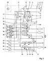
- the system according to Fig. 5 has a check valve 64, which on the one hand takes the place of the switching valves 60 and 63 and on the other hand, the function of the locking position of the relief valves 18 and 22 of the system according to Fig. 1 he brings. Again, it is necessary to form the control group 49 in the supply line 50, 53, a spill valve 51 and a check valve 52, in any order to arrange.
- the circle III and the circle IV are here again in accordance with the embodiment of the Fig. 1 built up.
- the embodiment of the Fig. 6 has the peculiarity that the two relief valves 18 and 22 of the circles I and II, a common pressure limiter 65 is connected upstream.
- the plant is otherwise constructed as it already is Fig. 5 shows.
- the two control groups 48 and 49 are formed, by the spill valve 51 and the check valve 52.
- the solenoid valve 26 can be omitted here.
- the operation of the compressor 4 to form the two control groups 48 and 49 is manageable from the foregoing.
- the control group 49 has only one circle, it is easy to imagine that the control group can also identify multiple circles, as shown for the control group 48.
Landscapes
- Engineering & Computer Science (AREA)
- Transportation (AREA)
- Mechanical Engineering (AREA)
- Valves And Accessory Devices For Braking Systems (AREA)
- Vehicle Body Suspensions (AREA)
Claims (10)
- Procédé d'exploitation d'une installation de production d'air comprimé comportant un compresseur, un régulateur de pression (13) et une soupape de protection multicircuit (47), d'un véhicule automobile, à laquelle peuvent être raccordés plusieurs circuits (I, II, III, IV, V) des récepteurs avec des hauteurs de pression au moins partiellement différentes, en ce que le compresseur (4) est commuté entre la phase de ralenti et la phase de fonctionnement sous charge, par l'intermédiaire du régulateur de pression (13) et une soupape d'échappement correspondante, par un signal généré par une électronique de commande (29), suivant la consommation d'air dans les différents circuits des récepteurs, caractérisé en ce que les circuits (I, II, III, IV, V) des récepteurs avec les différentes hauteurs de pression sont, par un ou plusieurs éléments, divisés ou réunis sur le plan de la technique de commande en au moins deux groupes de commande (48, 49) dont le premier groupe de commande (48) comprend ou comporte plusieurs circuits (par exemple I, II, III, IV) comprenant le circuit (par exemple III) avec la hauteur de pression minimale, et le deuxième groupe de commande (49) comprend ou comporte le circuit (par exemple V) avec la hauteur de pression maximale, qu'on utilise de l'air comprimé dans un circuit du premier groupe de commande (48) commandant le circuit avec la hauteur de pression la plus élevée (par exemple I, II) de ce groupe de commande (48) qui ne comporte pas le circuit (par exemple V) du deuxième groupe de commande (49) ave la hauteur de pression maximale, le régulateur de pression (13) et le compresseur (4), et en ce que le compresseur (4) est commandé différemment, entre la phase de ralenti et la phase de fonctionnement sous charge, par l'intermédiaire du régulateur de pression (13) et la soupape d'échappement correspondante, par un signal généré par l'électronique de commande (29), suivant le circuit des groupes de commande (48, 49) dans lequel on a une consommation d'air.
- Procédé selon la revendication 1, caractérisé en ce que les pressions maximales, s'appliquant aux sorties vers les réservoirs des différents circuits (I, II ; V) des récepteurs, au moins du premier groupe de commande (48) avec la hauteur de pression minimale et du deuxième groupe de commande (49) avec la hauteur de pression maximale, sont mesurées chacune et utilisées pour la commande du cycle fonctionnement sous charge-ralenti du compresseur (4).
- Procédé selon la revendication 1 ou 2, caractérisé en ce que dans le premier groupe de commande (48), comprenant la hauteur de pression minimale, des circuits (I, II, III, IV) des récepteurs, il se produit la répartition de l'air comprimé, produit par le compresseur (4) en phase de fonctionnement sous charge, entre les différents circuits des récepteurs, avec utilisation de soupapes mécaniques et pneumatiques, en particulier de soupapes de trop-plein, de limiteurs de pression, de soupapes de commutation et/ou de clapets de non-retour et similaires.
- Procédé selon une ou plusieurs des revendications 1 à 3, caractérisé en ce qu'on empêche un échange d'air entre le deuxième groupe de commande (49) présentant la hauteur de pression maximale et le premier groupe de commande (48) présentant la hauteur de pression minimale.
- Dispositif de traitement d'air comprimé pour une installation de production d'air comprimé comportant un compresseur, d'un véhicule automobile, avec un régulateur de pression (13), un sécheur d'air (6), une soupape de protection multicircuit (47) et une électronique de commande (29) lesquels forment une unité de construction commune; à l'intérieur de l'unité de construction commune étant prévues des soupapes mécaniques et pneumatiques associées aux différents circuits des récepteurs, en particulier des soupapes de trop-plein, des limiteurs de pression, des soupapes de commutation et/ou des clapets de non-retour et similaires, caractérisé en ce que les circuits des récepteurs sont divisés sur le plan de la technique de commande, par un ou plusieurs éléments, en au moins deux groupes de commande (48, 49) dont le premier groupe de commande (48) comprend ou comporte plusieurs circuits (par exemple I, II, III, IV) comprenant le circuit (par exemple III) avec la hauteur de pression minimale, et le deuxième groupe de commande (49) comprend ou comporte le circuit (par exemple V) avec la hauteur de pression maximale, qu'on utilise de l'air comprimé dans un circuit du premier groupe de commande (48) commandant le circuit avec la hauteur de pression la plus élevée (par exemple I, II) de ce groupe de commande (48) qui ne comporte pas le circuit (par exemple V) du deuxième groupe de commande (49) ave la hauteur de pression maximale, le régulateur de pression (13) et le compresseur (4)" entre la phase de ralenti et la phase de fonctionnement sous charge, par l'intermédiaire du régulateur de pression (13) et la soupape d'échappement correspondante, par un signal généré par l'électronique de commande (29), suivant le circuit des groupes de commande (48, 49) dans lequel on a une consommation d'air.
- Dispositif de traitement d'air comprimé selon la revendication 5, caractérisé en ce que l'élément provoquant la division sur le plan de la technique de commande en au moins deux groupes de commande (48, 49) comprend une soupape de trop-plein (51) et un clapet de non-retour (52) dans la conduite d'alimentation (50, 53) menant au circuit (par exemple V) du deuxième groupe de commande (49) présentant la hauteur de pression maximale.
- Dispositif de traitement d'air comprimé selon la revendication 5, caractérisé en ce que l'élément provoquant la division, sur le plan de la technique de commande, en au moins deux groupes de commande (48, 49) comprend une soupape d'arrêt (58) dans la conduite d'alimentation (50, 53) menant au circuit (par exemple V) du deuxième groupe de commande (49) présentant la hauteur de pression maximale.
- Dispositif de traitement d'air comprimé selon la revendication 5, caractérisé en ce que l'élément provoquant la division, sur le plan de la technique de commande, en au moins deux groupes de commande (48, 49) comprend une soupape de commutation (60 ou 63) couplée en aval du clapet de non-retour (8) définissant l'aération centrale (9).
- Dispositif de traitement d'air comprimé selon les revendications 5 et 6, caractérisé en ce que l'élément provoquant la division, sur le plan de la technique de commande, en au moins deux groupes de commande (48, 49), comprend une soupape d'arrêt (64) qui est disposée en amont des soupapes de trop-plein (18, 22) des circuits (I, II).
- Dispositif de traitement d'air comprimé selon les revendications 5 et 6, caractérisé en ce que l'élément provoquant la division, sur le plan de la technique de commande, en au moins deux groupes de commande (48, 49), comprend un limiteur de pression (65) qui est disposé en amont des soupapes de trop-plein (18, 22) des circuits (I, II).
Applications Claiming Priority (2)
| Application Number | Priority Date | Filing Date | Title |
|---|---|---|---|
| DE2003138162 DE10338162B3 (de) | 2003-08-20 | 2003-08-20 | Verfahren zum Betreiben einer Druckluftbeschaffungsanlage eines Kraftfahrzeuges sowie Druckluftaufbereitungseinrichtung |
| DE10338162 | 2003-08-20 |
Publications (3)
| Publication Number | Publication Date |
|---|---|
| EP1508488A1 EP1508488A1 (fr) | 2005-02-23 |
| EP1508488B1 EP1508488B1 (fr) | 2006-10-18 |
| EP1508488B2 true EP1508488B2 (fr) | 2009-07-29 |
Family
ID=34042203
Family Applications (1)
| Application Number | Title | Priority Date | Filing Date |
|---|---|---|---|
| EP04019344A Active EP1508488B2 (fr) | 2003-08-20 | 2004-08-14 | Installation de production d'air comprimé pour véhicule et méthode pour le faire fonctionner |
Country Status (2)
| Country | Link |
|---|---|
| EP (1) | EP1508488B2 (fr) |
| DE (2) | DE10338162B3 (fr) |
Families Citing this family (17)
| Publication number | Priority date | Publication date | Assignee | Title |
|---|---|---|---|---|
| DE102006023606A1 (de) * | 2006-05-19 | 2007-11-22 | Knorr-Bremse Systeme für Nutzfahrzeuge GmbH | Druckluftversorgungseinrichtung für ein Nutzfahrzeug |
| DE102006023728A1 (de) | 2006-05-19 | 2007-11-29 | Knorr-Bremse Systeme für Nutzfahrzeuge GmbH | Druckluftversorgungseinrichtung für ein Nutzfahrzeug |
| DE102006036017B4 (de) * | 2006-08-02 | 2008-07-31 | Haldex Brake Products Gmbh | Druckluftbereitstellungseinheit |
| DE102006054813A1 (de) * | 2006-11-22 | 2008-05-29 | Wabco Gmbh | Verfahren zur Druckluftversorgung in einem Fahrzeug |
| DE102007002020A1 (de) * | 2007-01-13 | 2008-07-17 | Wabco Gmbh | Anhängefahrzeugbrems- und Luftfederungsanlage |
| DE102007005987B4 (de) * | 2007-02-07 | 2010-09-09 | Knorr-Bremse Systeme für Nutzfahrzeuge GmbH | Ventileinrichtung für eine Druckluftversorgungseinrichtung und Druckluftversorgungsanlage |
| DE102008004807B4 (de) * | 2007-02-07 | 2012-10-31 | Knorr-Bremse Systeme für Nutzfahrzeuge GmbH | Druckluftversorgungsanlage und Verfahren zum Betreiben einer Druckluftversorgungsanlage |
| DE102007009767B4 (de) * | 2007-02-27 | 2009-11-12 | Knorr-Bremse Systeme für Nutzfahrzeuge GmbH | Druckluftversorgungseinrichtung für ein Nutzfahrzeug und Verfahren zum Betreiben einer Druckluftversorgungseinrichtung |
| DE102007035163B4 (de) * | 2007-07-25 | 2012-10-18 | Knorr-Bremse Systeme für Nutzfahrzeuge GmbH | Druckluftsystem |
| DE102008031318B3 (de) * | 2008-07-02 | 2010-01-07 | Knorr-Bremse Systeme für Nutzfahrzeuge GmbH | Lufttrockner für turboaufgeladene Kompressoren |
| DE102009029898A1 (de) | 2009-06-23 | 2010-12-30 | Wabco Gmbh | Druckluftversorgungssystem für einen Druckluftverbraucherkreis, insbesondere für ein Luftfederungssystem |
| DE102010031306B4 (de) | 2010-07-14 | 2014-11-27 | Haldex Brake Products Gmbh | Druckluftaufbereitungseinrichtung mit zwei Lufttrocknungskartuschen |
| DE102010054712B4 (de) | 2010-12-16 | 2023-06-07 | Zf Cv Systems Hannover Gmbh | Druckluftversorgungsanlage und pneumatisches System |
| DE102011053707B4 (de) | 2011-09-16 | 2017-01-26 | Haldex Brake Products Aktiebolag | Druckluftaufbereitungseinheit |
| DE102011084921A1 (de) | 2011-10-20 | 2013-04-25 | Continental Teves Ag & Co. Ohg | Kompressorschaltung für eine pneumatische Regelvorrichtung eines Fahrzeugs |
| DE102015115368A1 (de) | 2015-09-11 | 2017-03-16 | Knorr-Bremse Systeme für Schienenfahrzeuge GmbH | Verfahren und Einrichtung zur Steuerung einer Lufttrocknereinheit einer Luftversorgungsanlage für die Haupt- und Hilfsluftversorgung, insbesondere für ein Schienenfahrzeug |
| DE102016201222A1 (de) * | 2016-01-28 | 2017-08-03 | Voith Patent Gmbh | Verfahren zur Überwachung eines Fahrzeugdruckluftsystems |
Citations (12)
| Publication number | Priority date | Publication date | Assignee | Title |
|---|---|---|---|---|
| US3023765A (en) † | 1959-12-01 | 1962-03-06 | Bendix Westinghouse Automotive | Multipressure supply system |
| DE1208207B (de) † | 1960-10-20 | 1965-12-30 | Bosch Gmbh Robert | Druckluft-Erzeugungsanlage in Fahrzeugen, insbesondere Kraftfahrzeugen, mit Druckluft-bremse und Druckluftfederung |
| DE2837506A1 (de) † | 1978-08-28 | 1980-03-06 | Graubremse Gmbh | Druckluftbeschaffungsanlage fuer mehrere verbraucher |
| DE3412979A1 (de) † | 1984-04-06 | 1985-10-24 | Wabco Westinghouse Fahrzeugbremsen GmbH, 3000 Hannover | Drucklufterzeugungseinrichtung mit zwei kreisen mit unterschiedlichen druecken |
| DE3514989A1 (de) † | 1985-04-25 | 1986-10-30 | Knorr-Bremse AG, 8000 München | Druckluftversorgungseinrichtung fuer fahrzeug-druckluftanlagen |
| DE3637741A1 (de) † | 1986-11-05 | 1988-05-11 | Wabco Westinghouse Fahrzeug | Drucklufterzeugungsanlage |
| EP0496958A1 (fr) † | 1991-01-31 | 1992-08-05 | Robert Bosch Gmbh | Système de freinage à l'air comprimé pour véhicules |
| EP0561171A1 (fr) † | 1992-03-20 | 1993-09-22 | Robert Bosch Gmbh | Valve de protection pour plusieurs circuits |
| DE19835638A1 (de) † | 1998-08-06 | 2000-02-17 | Knorr Bremse Systeme | Elektronische Druckluftaufbereitungsanlage |
| DE19701059C2 (de) † | 1997-01-15 | 2000-12-21 | Lohmann Therapie Syst Lts | Acetylsalicylsäure enthaltendes transdermales therapeutisches System mit Resorptionsverstärkung |
| DE10220791A1 (de) † | 2002-05-10 | 2003-11-27 | Haldex Brake Prod Gmbh | Druckluftverteilungseinrichtung für Kfz-Druckluftanlagen |
| DE10333610A1 (de) † | 2003-07-24 | 2005-02-24 | Haldex Brake Products Gmbh | Druckluftaufbereitungseinrichtung für Kraftfahrzeug-Druckluftanlagen |
Family Cites Families (6)
| Publication number | Priority date | Publication date | Assignee | Title |
|---|---|---|---|---|
| DE2950904C2 (de) * | 1979-12-18 | 1982-02-18 | Graubremse Gmbh, 6900 Heidelberg | In Kraftfahrzeugen zu verwendendes Mehrkreisschutzventil |
| DE4421575C2 (de) * | 1994-06-21 | 1997-07-03 | Grau Gmbh | Druckregler für Druckluftbeschaffungsanlagen von Kraftfahrzeugen |
| DE19515895A1 (de) * | 1995-04-29 | 1996-10-31 | Bosch Gmbh Robert | Druckluft-Versorgungseinrichtung für Fahrzeug-Druckluftanlagen sowie Verfahren zum Steuern der Druckluft-Versorgungseinrichtung |
| DE19544621C1 (de) * | 1995-11-30 | 1997-01-30 | Grau Gmbh | Druckluftaufbereitungseinrichtung für Kraftfahrzeug-Druckluftanlagen |
| DE19700243C1 (de) * | 1997-01-07 | 1998-04-02 | Grau Gmbh | Druckluftaufbereitungseinrichtung für Kraftfahrzeug-Druckluftanlagen |
| DE19710814C1 (de) * | 1997-03-15 | 1998-07-09 | Grau Gmbh | Druckluftaufbereitungseinrichtung für Druckluftbeschaffungsanlagen auf Kraftfahrzeugen |
-
2003
- 2003-08-20 DE DE2003138162 patent/DE10338162B3/de not_active Expired - Fee Related
-
2004
- 2004-08-14 EP EP04019344A patent/EP1508488B2/fr active Active
- 2004-08-14 DE DE200450001778 patent/DE502004001778D1/de active Active
Patent Citations (12)
| Publication number | Priority date | Publication date | Assignee | Title |
|---|---|---|---|---|
| US3023765A (en) † | 1959-12-01 | 1962-03-06 | Bendix Westinghouse Automotive | Multipressure supply system |
| DE1208207B (de) † | 1960-10-20 | 1965-12-30 | Bosch Gmbh Robert | Druckluft-Erzeugungsanlage in Fahrzeugen, insbesondere Kraftfahrzeugen, mit Druckluft-bremse und Druckluftfederung |
| DE2837506A1 (de) † | 1978-08-28 | 1980-03-06 | Graubremse Gmbh | Druckluftbeschaffungsanlage fuer mehrere verbraucher |
| DE3412979A1 (de) † | 1984-04-06 | 1985-10-24 | Wabco Westinghouse Fahrzeugbremsen GmbH, 3000 Hannover | Drucklufterzeugungseinrichtung mit zwei kreisen mit unterschiedlichen druecken |
| DE3514989A1 (de) † | 1985-04-25 | 1986-10-30 | Knorr-Bremse AG, 8000 München | Druckluftversorgungseinrichtung fuer fahrzeug-druckluftanlagen |
| DE3637741A1 (de) † | 1986-11-05 | 1988-05-11 | Wabco Westinghouse Fahrzeug | Drucklufterzeugungsanlage |
| EP0496958A1 (fr) † | 1991-01-31 | 1992-08-05 | Robert Bosch Gmbh | Système de freinage à l'air comprimé pour véhicules |
| EP0561171A1 (fr) † | 1992-03-20 | 1993-09-22 | Robert Bosch Gmbh | Valve de protection pour plusieurs circuits |
| DE19701059C2 (de) † | 1997-01-15 | 2000-12-21 | Lohmann Therapie Syst Lts | Acetylsalicylsäure enthaltendes transdermales therapeutisches System mit Resorptionsverstärkung |
| DE19835638A1 (de) † | 1998-08-06 | 2000-02-17 | Knorr Bremse Systeme | Elektronische Druckluftaufbereitungsanlage |
| DE10220791A1 (de) † | 2002-05-10 | 2003-11-27 | Haldex Brake Prod Gmbh | Druckluftverteilungseinrichtung für Kfz-Druckluftanlagen |
| DE10333610A1 (de) † | 2003-07-24 | 2005-02-24 | Haldex Brake Products Gmbh | Druckluftaufbereitungseinrichtung für Kraftfahrzeug-Druckluftanlagen |
Non-Patent Citations (3)
| Title |
|---|
| "Grundlehrgang Druckluft-Bremsanlage", WABCO TRAINING JANUAR 2001, January 2001 (2001-01-01), WABCO FAHRZEUGBREMSEN, HANNOVER, pages 07/8 - 07/9 † |
| "Kraftfahrtechnisches Taschenbuch", vol. 24.AUFL., ROBERT BOSCH GMBH,2002, STUTTGART, ISBN: 3528138769, pages: 750 - 753 † |
| ING. (GRAD.) PETER BERG: "Grundlagen, Systeme und Pläne", DRUCKLUFTANLAGEN FÜR NUTZFAHRZEUGE 1, TECHNISCHE UNTERRICHTUNG (BOSCH), February 1998 (1998-02-01), ROBERT BOSCH GMBH UNTERNEHMENSBEREICH KRAFTFAHRZEUG-AUSRÜSTUNG, ABTEILUNG TECHNISCHE INFORMATION (KH/VDT), STUTTGART † |
Also Published As
| Publication number | Publication date |
|---|---|
| DE10338162B3 (de) | 2005-06-02 |
| EP1508488A1 (fr) | 2005-02-23 |
| EP1508488B1 (fr) | 2006-10-18 |
| DE502004001778D1 (de) | 2006-11-30 |
Similar Documents
| Publication | Publication Date | Title |
|---|---|---|
| EP1508488B2 (fr) | Installation de production d'air comprimé pour véhicule et méthode pour le faire fonctionner | |
| EP1464557B1 (fr) | Dispositif de traitement d'air comprimé | |
| EP1785325B2 (fr) | Dispositif de réglage d'un système de freinage à air comprimé pour un véhicule | |
| EP3145769B1 (fr) | Moyen de commande de freinage électropneumatique avec purge automatique du frein à accumulation en cas de panne de courant | |
| DE4421575C2 (de) | Druckregler für Druckluftbeschaffungsanlagen von Kraftfahrzeugen | |
| EP3668766B1 (fr) | Module d'alimentation électro pneumatique pour fournir une pression à un remorque | |
| EP2129566B1 (fr) | Dispositif d'alimentation en air comprimé pour un véhicule utilitaire et procédé pour la commande d'un dispositif d'alimentation en air comprimé | |
| EP2139735B1 (fr) | Dispositif d'alimentation en air comprimé conçu pour un véhicule utilitaire et procédé pour faire fonctionner ce dispositif d'alimentation en air comprimé | |
| EP2829744B1 (fr) | Dispositif d'alimentation en air pour un système d'air comprimé d'un véhicule et un tel système d'air comprimé | |
| EP0776807B1 (fr) | Dispositif pour le traitement de l'air comprimé pour systèmes à air comprimé des véhicules automobiles | |
| DE19821420C1 (de) | Druckluftaufbereitungseinrichtung für Druckluftbeschaffungsanlagen auf Kraftfahrzeugen | |
| DE4108915C2 (de) | Hydraulische Einrichtung zur Druckmittelversorgung eines bevorrechtigten Primärlastkreises | |
| EP2024212B1 (fr) | Installation d'alimentation en air comprimé pour véhicule industriel | |
| DE19700243C1 (de) | Druckluftaufbereitungseinrichtung für Kraftfahrzeug-Druckluftanlagen | |
| DE3545021A1 (de) | Elektro-pneumatische bremsanlage | |
| EP1647473A1 (fr) | Installation pour véhicule avec suspension pneumatique et essieu rétractable | |
| EP1361132B1 (fr) | Dispositif de distribution d'air comprimé pour un système pneumatique pour automobile | |
| DE10220790C1 (de) | Druckluftaufbereitungseinrichtung für Kfz-Druckluftanlagen | |
| DE102008033696A1 (de) | Mehrkreisschutzventil für eine Druckluftversorgungsanlage | |
| EP1527974A2 (fr) | Système de traitement d'air et méthode pour alimenter un système de freinage d'un véhicule utilitaire à moteur avec de l'air comprimé | |
| EP2789512B1 (fr) | Dispositif de préparation d'air comprimé pour un véhicule utilitaire | |
| DE102009055210B4 (de) | Druckluftanlage | |
| EP2226205A1 (fr) | Procédé pour le réglage de pression de pneux et système de réglage de la pression de pneux | |
| DE102012102490B4 (de) | Druckluftaufbereitungseinrichtung für ein Nutzfahrzeug |
Legal Events
| Date | Code | Title | Description |
|---|---|---|---|
| PUAI | Public reference made under article 153(3) epc to a published international application that has entered the european phase |
Free format text: ORIGINAL CODE: 0009012 |
|
| AK | Designated contracting states |
Kind code of ref document: A1 Designated state(s): AT BE BG CH CY CZ DE DK EE ES FI FR GB GR HU IE IT LI LU MC NL PL PT RO SE SI SK TR |
|
| AX | Request for extension of the european patent |
Extension state: AL HR LT LV MK |
|
| 17P | Request for examination filed |
Effective date: 20050226 |
|
| GRAP | Despatch of communication of intention to grant a patent |
Free format text: ORIGINAL CODE: EPIDOSNIGR1 |
|
| GRAS | Grant fee paid |
Free format text: ORIGINAL CODE: EPIDOSNIGR3 |
|
| AKX | Designation fees paid |
Designated state(s): DE FR |
|
| GRAA | (expected) grant |
Free format text: ORIGINAL CODE: 0009210 |
|
| AK | Designated contracting states |
Kind code of ref document: B1 Designated state(s): DE FR |
|
| REF | Corresponds to: |
Ref document number: 502004001778 Country of ref document: DE Date of ref document: 20061130 Kind code of ref document: P |
|
| ET | Fr: translation filed | ||
| PLBI | Opposition filed |
Free format text: ORIGINAL CODE: 0009260 |
|
| PLAX | Notice of opposition and request to file observation + time limit sent |
Free format text: ORIGINAL CODE: EPIDOSNOBS2 |
|
| 26 | Opposition filed |
Opponent name: WABCO GMBH Effective date: 20070718 |
|
| PLBB | Reply of patent proprietor to notice(s) of opposition received |
Free format text: ORIGINAL CODE: EPIDOSNOBS3 |
|
| PUAH | Patent maintained in amended form |
Free format text: ORIGINAL CODE: 0009272 |
|
| STAA | Information on the status of an ep patent application or granted ep patent |
Free format text: STATUS: PATENT MAINTAINED AS AMENDED |
|
| 27A | Patent maintained in amended form |
Effective date: 20090729 |
|
| AK | Designated contracting states |
Kind code of ref document: B2 Designated state(s): DE FR |
|
| REG | Reference to a national code |
Ref country code: FR Ref legal event code: PLFP Year of fee payment: 13 |
|
| REG | Reference to a national code |
Ref country code: DE Ref legal event code: R082 Ref document number: 502004001778 Country of ref document: DE Representative=s name: REHBERG HUEPPE + PARTNER PATENTANWAELTE PARTG , DE Ref country code: DE Ref legal event code: R081 Ref document number: 502004001778 Country of ref document: DE Owner name: HALDEX BRAKE PRODUCTS AKTIEBOLAG, SE Free format text: FORMER OWNER: HALDEX BRAKE PRODUCTS GMBH, 69123 HEIDELBERG, DE |
|
| REG | Reference to a national code |
Ref country code: FR Ref legal event code: TP Owner name: HALDEX BRAKE PRODUCTS AKTIEBOLAG, SE Effective date: 20170123 |
|
| REG | Reference to a national code |
Ref country code: FR Ref legal event code: PLFP Year of fee payment: 14 |
|
| REG | Reference to a national code |
Ref country code: FR Ref legal event code: PLFP Year of fee payment: 15 |
|
| PGFP | Annual fee paid to national office [announced via postgrant information from national office to epo] |
Ref country code: DE Payment date: 20220622 Year of fee payment: 19 |
|
| PGFP | Annual fee paid to national office [announced via postgrant information from national office to epo] |
Ref country code: FR Payment date: 20230821 Year of fee payment: 20 |
|
| REG | Reference to a national code |
Ref country code: DE Ref legal event code: R119 Ref document number: 502004001778 Country of ref document: DE |