EP0050362A2 - Dispositif de nettoyage de faisceaux de tubes - Google Patents
Dispositif de nettoyage de faisceaux de tubes Download PDFInfo
- Publication number
- EP0050362A2 EP0050362A2 EP81108574A EP81108574A EP0050362A2 EP 0050362 A2 EP0050362 A2 EP 0050362A2 EP 81108574 A EP81108574 A EP 81108574A EP 81108574 A EP81108574 A EP 81108574A EP 0050362 A2 EP0050362 A2 EP 0050362A2
- Authority
- EP
- European Patent Office
- Prior art keywords
- lance
- frame
- support
- lances
- portal
- Prior art date
- Legal status (The legal status is an assumption and is not a legal conclusion. Google has not performed a legal analysis and makes no representation as to the accuracy of the status listed.)
- Withdrawn
Links
Images


Classifications
-
- F—MECHANICAL ENGINEERING; LIGHTING; HEATING; WEAPONS; BLASTING
- F28—HEAT EXCHANGE IN GENERAL
- F28G—CLEANING OF INTERNAL OR EXTERNAL SURFACES OF HEAT-EXCHANGE OR HEAT-TRANSFER CONDUITS, e.g. WATER TUBES OR BOILERS
- F28G1/00—Non-rotary, e.g. reciprocated, appliances
- F28G1/16—Non-rotary, e.g. reciprocated, appliances using jets of fluid for removing debris
-
- F—MECHANICAL ENGINEERING; LIGHTING; HEATING; WEAPONS; BLASTING
- F28—HEAT EXCHANGE IN GENERAL
- F28G—CLEANING OF INTERNAL OR EXTERNAL SURFACES OF HEAT-EXCHANGE OR HEAT-TRANSFER CONDUITS, e.g. WATER TUBES OR BOILERS
- F28G15/00—Details
- F28G15/02—Supports for cleaning appliances, e.g. frames
Definitions
- the invention relates to a device for cleaning tube bundles with a cleaning liquid (water), which is applied by high-pressure nozzles arranged along or into the tube bundles, for example arranged on elongated tube pieces (lances).
- a cleaning liquid water
- the cleaning of tube bundles is particularly important in the chemical and petrochemical industries.
- the tube bundles in question are predominantly parts of heat exchangers and similar devices.
- the tube bundles are mainly held together at one end by an end plate with a laterally projecting flange.
- Pieces of pipe are used for the internal cleaning of the pipes, at the working end of which a high-pressure nozzle is arranged.
- the lances are inserted into the pipes to be cleaned.
- the invention has for its object to propose a device for cleaning tube bundles, which is simple in construction and handling and also ensures universal use in practice.
- the cleaning system according to the invention is characterized in that a supporting structure (frame portal) for a group of lances and supporting devices for at least one tube bundle are arranged on a trolley and are movable relative to one another.
- An essential idea of the invention is therefore the mobility of a complete cleaning system for tube bundles.
- the necessary units are arranged on a structure that can be moved on road or rail, and in such a way that all Aggregates are displaceable relative to one another. This enables full cleaning of the tube bundle in the interior of the individual tubes as well as on the outside in a confined space.
- a three-dimensional supporting structure in the form of a frame portal is arranged on the running gear (on rails).
- This receives a support frame (lance frame) for holding and guiding a plurality of lances, such that they can be moved in the plane or in the direction of the longitudinal axis of the tubes.
- the lance frame is expediently mounted on the frame portal both in height and in the longitudinal direction.
- this device includes at least one, but preferably two, spaced-apart supporting devices for the tube bundle to be cleaned.
- These support devices are also movable (on rails) arranged on the chassis. These are preferably a flange bracket and a bundle bracket. The former is designed so that the flange of the tube bundle facing the cleaning tools is supported on rollers.
- the bundle block is provided with a plurality of support rollers for supporting the tubes.
- at least one of these support devices is provided with rotatably driven supports for the tube bundle, in particular the support rollers of the flange bracket, in order to be able to rotate the tube bundle about the edgen longitudinal axis.
- the frame portal is also provided with cleaning tools for carrying out external cleaning, namely a spray bar or individual high-pressure nozzles. These are also arranged to be displaceable in height, so that an external and internal cleaning can alternatively or simultaneously be carried out by moving the frame portal and the tube bundle relative to one another.
- the support devices for the tube bundle can be moved in the longitudinal direction on the chassis.
- a chassis is equipped with two complete tube bundle cleaning systems.
- One remains to carry out cleaning work on the undercarriage, the cleaning being carried out essentially in the manner described on the undercarriage by given movement possibilities both of a supporting structure for cleaning tools and for supporting devices of the tube bundle.
- a second complete cleaning device is removably arranged on the undercarriage and is set down next to the undercarriage for carrying out the cleaning work and installed on a predetermined floor area.
- the units required for this, namely a supporting structure for cleaning tools and supporting devices for the tube bundle, are preferred adjustable support feet, which enable exact relative alignment on the given surface.
- the present invention is preferably practiced so that a gate portal with up and down movable cleaning tools for external cleaning and support devices of the type described remain on the chassis, while a frame portal and also, for example, consisting of a flange bracket and a bundle bracket support devices for performing the internal cleaning of Pipes are placed on the floor and set up.
- the frame portal or the lances, lance frames etc. arranged thereon can be designed in the described and claimed embodiment.
- the invention relates to a special embodiment of a lance which is suitable for heavy deposits or dirt in the pipes.
- the lance in question is driven according to the invention rotatably about its own longitudinal axis, thereby fulfilling the function of a drilling lance.
- the rotary drive takes place at the free end of the drilling lance, preferably by means of a hydraulic motor via a gear which can be moved back and forth with the lance.
- a special support is also provided according to the invention.
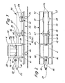
- Such a tube bundle 30 consists of a plurality of parallel-oriented tubes arranged, for example, with a circular outline, which are connected at one end to an end plate 31. This forms a circumferential, protruding flange 32.
- the device for cleaning such tube bundles 30 is on a one-piece drive in the present case Werk 33 mounted, which is designed here as a two-axle car with pneumatic tires 34.
- the entire cleaning system can be transported on the road with the aid of this undercarriage 33.
- well-known supports are advantageously extended to relieve the wheels 34.
- the cleaning device consists in the basic structure of a cleaning unit 35 and a support device for the tube bundle 30, such that the tubes of the same lie essentially horizontally.
- the cleaning unit 35 and the tube bundle 30 are arranged displaceably relative to one another on the undercarriage 33 in order to be able to carry out internal cleaning (cleaning inside the tubes) and external cleaning thereof.
- the cleaning unit 35 consists of a supporting structure in the form of a frame portal 36 for the cleaning tools.
- the frame portal 36 is formed by four upright supports 37 and 38 arranged at corners and upper and lower, transverse or horizontal frames 39 and 40, respectively.
- the lower frame 40 is equipped with wheels 41 which run on rails 42 on the edge of the chassis 33.
- a support structure - in the present case a lifting frame 43 extending in the horizontal plane - can be moved up and down within the frame portal 36.
- the lifting frame 43 is guided in a suitable manner in the area of the supports 37, 38 and can be moved up and down, for example, by a chain drive.
- the lifting frame 43 is the carrier of a cabin K for operating personnel, but also for the cleaning tools.
- the latter is a plurality of spray tubes which extend in the longitudinal direction of the undercarriage 33, namely lances 44, with high-pressure nozzles 45 at their free ends.
- These lances 44 - in the present case three lying side by side in a horizontal plane - are slidably supported and guided in a supporting structure in the form of a lance frame 46 such that they can preferably be inserted together into the tubes of the adjacent or subsequent tube bundle 30.
- the lances 44 or their high-pressure nozzles 45 are moved through the pipes to be cleaned in each case over the entire length, a cleaning liquid (water) escaping at high pressure cleaning the inside of the pipes.
- the lance frame 46 is designed as an elongated, box-shaped supporting structure and is connected to the underside of the lifting frame 43. By moving the same up and down the lance frame and thus the lances 44 can be brought to the required height. At the start of the cleaning process, the lance frame 46 is brought into the required relative position by moving the frame portal 36 or, if necessary, by moving the lance frame 46 relative to the latter.
- the tube bundle 30 rests on two support devices, namely a flange bracket 47 and a bundle bracket 48.
- the flange bracket 47 is equipped so that the flange 32 has a stable support.
- two support rollers 49 are provided in the transverse direction at a distance from one another see with longitudinal axes of rotation. The distance between the support rollers 49 can be adjusted by means of an adjusting device (handwheel 50 in FIG. 16). This also makes it possible to adapt to different diameters of the tube bundle 30 or the flange 32.
- the support rollers 49 can be driven in rotation by an (electric) drive motor (not shown in detail) for each support roller 49. By driving the support rollers 49 in the same direction, the entire tube bundle 30 is rotated, so that all tubes are successively brought into a working position for cleaning can.
- the bundle bracket 48 is arranged at a distance from the flange bracket 47 and provided with a plurality of support rollers 51. These extend freely rotatably in the longitudinal direction of the tube bundle 30. As can be seen, for example, from FIG. 5, four support rollers 51 with different heights - two each at the same height - are arranged. Smaller tube bundles 30 lie on the inner support rollers 51, while larger tube bundles 30 are carried exclusively by the outer support rollers 51.
- Both support devices ie flange bracket 47 and bundle bracket 48, are equipped with a bogie and can be moved in the longitudinal direction of the bogie 33 with bogies 52 and 53.
- further rails 54 are arranged at a smaller distance from one another and between the rails 42 on the loading surface of the undercarriage 33.
- the optimal relative mobility given by the movability of the aforementioned units enables external cleaning to be carried out with the Cleaning unit 35.
- This is additionally equipped for this with high-pressure spray bars 55 and 56 on the front and rear, namely by arrangement on the lifting frame 43.
- the transverse high-pressure spray bars 55, 56 can be moved over this at a suitable height by moving the frame portal 36 and / or the tube bundle 30 be (position according to Fig. 3).
- the high-pressure spray bars 55, 56 direct cleaning fluid against the outside of the pipes. The entire area of the same can be grasped by rotating the tube bundle 30.
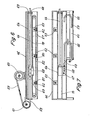
- the lance frame 46 is detachably attached to the frame portal 36 or to the lifting frame 43. It can be removed for external cleaning. The same applies to the transport phase of the facility.
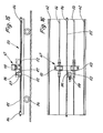
- the lance frame 46 is designed as an elongated hollow box. Within the same, the lances 44 are preferably arranged side by side in a horizontal plane. At one end, the lances 44 telescopically emerge from the lance frame 46.
- each lance 44 is assigned a separate feed chain 57, expediently with a common drive (not shown) for all feed chains 57.
- Each feed chain 57 is with the free back End of the lance 44 connected by a lance carrier 58.
- This is block-shaped and at the same time serves to connect a supply line in the form of a high-pressure hose 59 to the end of the lance 44.
- the lance carrier 58 is a coupling piece. Channels run within it and establish the flow connection.
- the high-pressure hose 59 is brought to the lance 44 in the axial direction thereof.
- the free part of the high-pressure hose 59 is wound onto a hose drum 60, which is arranged here on the top of the lance frame 46.
- the high-pressure hose 59 is guided to and from this hose drum 60 via a hose reel 61 which is arranged in front of the rear end of the lance frame 46 in such a way that the part of the high-pressure hose 59 running to the end of the lance 44 is guided essentially coaxially.
- the ends of the relatively long feed chain 57 are connected to the lance carrier 58, which is extended downwards accordingly. Between the upper and lower run of the feed chain 57 there extends a cross connection between the adjacent lances 44 in the form of a plurality of cross spindles 62.
- Spindle nuts 63 assigned to each lance 44 are mounted on them, which can be moved in the transverse direction by turning the cross spindles 62 and thereby Change the distance between the lances 44.
- the transverse spindles 62 which are spaced apart in the longitudinal direction, can be rotated together in one direction or the other by a common drive (lateral drive chains - not shown). It is expedient the lance 44 lying in the middle is immovable, while the lateral lances 44 are adjustable at a greater or smaller distance from it (see also FIG. 14).
- the cross spindles 62 or their spindle nuts 63 are connected to a separate lance guide. In the exemplary embodiments shown, this is designed as a lance support tube 64 with a square, in particular square, cross section. Such a enveloping lance support tube 64 is assigned to each lance 44. In the exemplary embodiment according to FIG. 6, the spindle nuts 63 are attached to the underside of the lance support tubes 64. A transverse displacement of the spindle nuts 63 also causes a transverse displacement of the lance support tubes 64 and thus the lances 44 themselves.
- the lance support tubes 64 extend within the lance frame 46.
- a guidance of the high-pressure hose 59 which deviates from the proposal of FIG. 6 is provided.
- This connects to the end of the lance 44, namely below it, via a specially designed lance carrier 58. Channels for guiding the cleaning liquid are formed in the appropriately designed lance carrier 58.
- the free part of the high pressure hose 59 is collected, guided and held in a hose trough 65 which is formed below the lance frame 46. This is open in the area in question opposite the hose trough 65, so that the high-pressure hose 59 can be moved between the positions shown, forming a wandering deflection 66.
- the transverse displacement of the lances 44 is also carried out here by corresponding movement of the lance support tubes 64. These are suspended from transverse spindles 62 by spindle nuts 63 attached to the top of each lance support tube 64 and can be displaced transversely by turning them.
- the advance of the lances 44 is also designed differently, namely by a common drive for all lances 44.
- their lance carriers 58 are combined by a common, transversely directed connecting rod 67 and can thus be moved together, for example by laterally arranged chain drives ( Not shown).
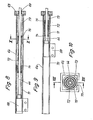
- the lance support tubes 64 are of particular importance since they guide, support and also protect the sensitive lances 44.
- the lance support tubes 64 are arranged side by side in the common lance frame 46.
- the lances 44 each pass through a bore 68 in an end wall 69 of the lance support tube 64. In this area, a slide bearing for the lance 44 is also formed.
- the lance support tube 64 is formed with a continuous slot 70 for the passage of the lance carrier 58 or another suitable coupling of the lance 44 with its drive. This is preferably arranged on the underside (Fig. 10). To prevent the lance 44, which deforms within the lance support tube 64, namely laterally deflecting, from passing through the slot 70, covering or supporting measures are provided.
- the lance support tube 64 enveloping support members, namely support springs.
- These are designed here as spring blocks 71, 72, 73 with a longitudinal dimension which is in each case considerably smaller than the total length of the lance 44 or the lance support tube 64.
- the helical spring blocks 71 envelop the lance 44 with mutual overlap.
- the spring block 72 has a smaller diameter than the adjacent spring blocks 71 and 73. These can therefore partially overlap one another with the support on appropriately shaped guide sleeves 74 and 75.
- the spring blocks 71..73 completely squeezed.
- the guide sleeves 74, 75 lie against each other.
- the lance 44 When the lance 44 is withdrawn and the spring blocks 71..73 are extended, the lance 44 is supported over its entire length, in particular against lateral deflection into the slot 70.
- the use of the spring blocks 71..73 allows large movement amplitudes to be mastered.
- FIGS. 11 and 12 An alternative solution to this topic is shown in FIGS. 11 and 12. Only in the area of the slot 70 is a cover provided, which is designed such that the lance carrier 58 (or another connecting means) can move through the slot 70 over the full length while maintaining the supporting function.
- the slot 70 is covered by an elongated coil spring 76 which extends in a transverse plane approximately over the full length of the lance support tube 64 in a corresponding slot-shaped recess 77.
- the coil spring 76 is designed with an extremely long amplitude and consists of a continuous spring wire.
- Each lance 44 is assigned a separate feed chain 57 here.
- the upper run 78 of this feed chain 57 is guided in the slot 70 of the lance support tube 64. With downward deflections of the lance 44, this support is provided on the upper run 78 of the feed chain 57, it being advantageous that the support with the lance 44 is conveyed without friction.
- the underside of the lance support tube 64 is formed by welded-on square profiles 79, on which the spindle nut 63 is attached for the transverse displacement of the lances 44.
- 14 shows the middle lance 44 which cannot be displaced.
- the cross spindle 62 is here without thread, only rotatably passed through the spindle nut 63. Rotations of the transverse spindle 62 accordingly do not cause any displacement of this spindle nut 63 and thus of the lance 44.
- the spindle nut 63 is provided with a downward projection 80 which has an opening 81 for the passage of the lower run 82 of the feed chain 57. This is guided and supported in the area of its lower run 82. In the region of the upper run 78, transverse support plates 83 are provided here between the supports formed by the spindle nuts 63.
- a traversing chain 85 which is guided in the center and anchored at the ends with chain tensioners 84, is provided.
- the traversing chain 85 is in engagement with a drive wheel 86 on the movable flange bracket 47.
- deflection sprockets 87 arranged offset therefrom, the traversing chain 85 is guided over the drive wheel 86 with sufficient looping and without the risk of lifting off. This is driven in one direction or another by a geared motor 88 attached to the flange bracket 47.
- the flange bracket 47 extends along the traversing chain 85 over the loading area of the undercarriage 33.
- chassis 33 which can be used simultaneously or alternatively on the spot.
- a cleaning device is lifted from the undercarriage 33 and placed at a suitable location on the existing surface.
- Another complete cleaning device remains on the chassis 33.
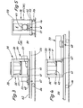
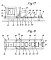
- a cleaning device for cleaning the outside of the pipes is designed to remain on the chassis 33 and a cleaning device for cleaning the inside is designed to be removable and removable.
- a supporting structure for the outside Cleaning tools in particular for a transversely directed high-pressure spray bar 55 arranged movably.
- a gate portal 89 which is provided with a chassis 91 having four wheels 90.
- the gate portal 89 consists of a transverse, U-shaped frame that is open at the bottom.
- a crossbar 92 for receiving the high-pressure spray bar 55 can be moved up and down there.
- the gate portal 89 is further provided in the area of the chassis 91 with gear boxes 93, in which drive elements (motor, gear) for the lifting movements of the crossbar 92 and for the movement of the gate portal 89 along the running rails 54 of the chassis 33 are accommodated.
- Supporting devices for the tube bundle 30 in the embodiment already described are assigned to the gate portal 89, namely a flange bracket 47 and a bundle cover 48, each movable. With the aid of these devices, a complete external cleaning of the tube bundle 30 can be carried out on the chassis 33.
- corresponding cleaning units are arranged loosely on the undercarriage 33, namely detachable.
- the support feet 94 are suitably height-adjustable so that an exact positioning of the frame portal 36 on the ground is possible.
- the tube frame 96 consists, for example, of only two inclined support surfaces 97 and 98, which exert a centering effect on the tube bundle 30 regardless of the size thereof.
- Flange frame 95 and tubular frame 96 are each provided with support feet 99 and 100 at the four corners, which also allow height adjustment.
- the frame portal 36 is expediently set down in the rear area of the undercarriage 33.
- the gate portal 89 is arranged adjacent to this. This is followed by flange frame 95 and tubular frame 96. In this arrangement, flange bracket 47 and bundle bracket 48 are located in the front area of chassis 33.
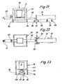
- a special embodiment of the lance 44 can be used for all described exemplary embodiments of cleaning devices.
- This lance 44 is driven to rotate about its own longitudinal axis and thus has the function of a drilling lance 101. It is suitable for removing thick, stuck deposits.
- the free end of the drilling lance 101 is connected to a gear box 102 or enters it a.
- a gearbox in particular a gear transmission 103, is accommodated in the gearbox 102, through which the rotary drive of a hydraulic motor 104 (or another motor) can be transmitted to the drilling lance 101.
- a high-pressure rotary connection 105 of a known type is attached here, which enables the connection of a high-pressure line (high-pressure hose) to the drilling lance 101 for the supply of the cleaning liquid.
- the drilling lance 101 is not guided in a lance support tube 64, but is exposed.
- a plurality of support bearings 106 are provided for support, which are spaced apart from one another in the starting position, but reduce their distance from one another up to the sealing position as the drilling lance 101 extends.
- the support bearings 106 in turn are connected to a feed spindle 107 which rotatably extends within the holder (lance frame) for the drilling lance 101.
- the feed screw 107 is driven by a motor 108 (hydraulic motor) rotating in one direction or the other, which is attached to the lance frame 46 in front of the head end thereof.
- a main spindle nut 109 is also mounted on the feed spindle 107 and is connected to the gearbox 102 and causes the same to be fed to the drilling lance 101.
- the feed spindle 107 is accommodated in an elongated housing 110.
- the drilling lance 101 can also be used in cleaning devices of other embodiments.
Landscapes
- Engineering & Computer Science (AREA)
- Chemical & Material Sciences (AREA)
- Combustion & Propulsion (AREA)
- Mechanical Engineering (AREA)
- General Engineering & Computer Science (AREA)
- Cleaning In General (AREA)
- Cleaning By Liquid Or Steam (AREA)
Applications Claiming Priority (2)
| Application Number | Priority Date | Filing Date | Title |
|---|---|---|---|
| DE19803039648 DE3039648A1 (de) | 1980-10-21 | 1980-10-21 | Rohrbuendel-reinigungsanlage |
| DE3039648 | 1980-10-21 |
Publications (2)
| Publication Number | Publication Date |
|---|---|
| EP0050362A2 true EP0050362A2 (fr) | 1982-04-28 |
| EP0050362A3 EP0050362A3 (fr) | 1982-09-15 |
Family
ID=6114842
Family Applications (1)
| Application Number | Title | Priority Date | Filing Date |
|---|---|---|---|
| EP81108574A Withdrawn EP0050362A3 (fr) | 1980-10-21 | 1981-10-20 | Dispositif de nettoyage de faisceaux de tubes |
Country Status (2)
| Country | Link |
|---|---|
| EP (1) | EP0050362A3 (fr) |
| DE (1) | DE3039648A1 (fr) |
Cited By (5)
| Publication number | Priority date | Publication date | Assignee | Title |
|---|---|---|---|---|
| FR2616260A1 (fr) * | 1987-06-05 | 1988-12-09 | Thome Jean Patrick | Dispositif de de contamination de l'interieur des tubes de generateurs de vapeur de reacteurs nucleaires |
| WO1994011694A1 (fr) * | 1992-11-12 | 1994-05-26 | Clyde Sootblowers Limited | Appareil de nettoyage pour les surfaces d'echange thermique et dispositif de buse ameliore pour celui-ci |
| WO2000017595A1 (fr) * | 1998-09-23 | 2000-03-30 | Idrojet S.A.S. | Dispositif de nettoyage |
| WO2012037560A3 (fr) * | 2010-09-17 | 2012-12-06 | Aquilex Hydrochem, Inc. | Ensemble et procédé de nettoyage de tube d'échangeur de chaleur semi-automatisé |
| US20220268535A1 (en) * | 2019-08-01 | 2022-08-25 | Tube Tech Industrial Limited | Tube cleaning system and method |
Families Citing this family (1)
| Publication number | Priority date | Publication date | Assignee | Title |
|---|---|---|---|---|
| DE102017117547A1 (de) | 2017-08-02 | 2019-02-07 | Alfred Kärcher SE & Co. KG | Vorrichtung zum Reinigen von Werkstücken, insbesondere bündelweise verbundenen Rohren |
Citations (7)
| Publication number | Priority date | Publication date | Assignee | Title |
|---|---|---|---|---|
| DE930959C (de) * | 1953-09-30 | 1955-07-28 | P Von Arx & Co A G | Einrichtung zur gleichzeitigen Behandlung der Innen- und Aussenflaeche von Metallrohren |
| CH309490A (de) * | 1952-02-23 | 1955-09-15 | Superior Ab | Russbläser. |
| FR1409433A (fr) * | 1964-07-17 | 1965-08-27 | Installation pour le nettoyage de faisceaux tubulaires ou analogues | |
| US3269659A (en) * | 1964-12-18 | 1966-08-30 | Halliburton Co | Apparatus for cleaning the inside of bundled tubes |
| US3843409A (en) * | 1970-06-26 | 1974-10-22 | Hydro Vel Services Inc | Heat exchanger cleaning system |
| FR2338476A1 (fr) * | 1976-01-16 | 1977-08-12 | Applic Tech Hydrauliques | Bancs de lavage interne et externe d'echangeurs et de condenseurs tubulaires comportant des amenagements de service |
| FR2347113A1 (fr) * | 1976-04-05 | 1977-11-04 | Nettoyage Ind Chimique | Installation de nettoyage automatique d'echangeurs thermiques a faisceaux tubulaires |
-
1980
- 1980-10-21 DE DE19803039648 patent/DE3039648A1/de not_active Ceased
-
1981
- 1981-10-20 EP EP81108574A patent/EP0050362A3/fr not_active Withdrawn
Patent Citations (7)
| Publication number | Priority date | Publication date | Assignee | Title |
|---|---|---|---|---|
| CH309490A (de) * | 1952-02-23 | 1955-09-15 | Superior Ab | Russbläser. |
| DE930959C (de) * | 1953-09-30 | 1955-07-28 | P Von Arx & Co A G | Einrichtung zur gleichzeitigen Behandlung der Innen- und Aussenflaeche von Metallrohren |
| FR1409433A (fr) * | 1964-07-17 | 1965-08-27 | Installation pour le nettoyage de faisceaux tubulaires ou analogues | |
| US3269659A (en) * | 1964-12-18 | 1966-08-30 | Halliburton Co | Apparatus for cleaning the inside of bundled tubes |
| US3843409A (en) * | 1970-06-26 | 1974-10-22 | Hydro Vel Services Inc | Heat exchanger cleaning system |
| FR2338476A1 (fr) * | 1976-01-16 | 1977-08-12 | Applic Tech Hydrauliques | Bancs de lavage interne et externe d'echangeurs et de condenseurs tubulaires comportant des amenagements de service |
| FR2347113A1 (fr) * | 1976-04-05 | 1977-11-04 | Nettoyage Ind Chimique | Installation de nettoyage automatique d'echangeurs thermiques a faisceaux tubulaires |
Cited By (7)
| Publication number | Priority date | Publication date | Assignee | Title |
|---|---|---|---|---|
| FR2616260A1 (fr) * | 1987-06-05 | 1988-12-09 | Thome Jean Patrick | Dispositif de de contamination de l'interieur des tubes de generateurs de vapeur de reacteurs nucleaires |
| WO1994011694A1 (fr) * | 1992-11-12 | 1994-05-26 | Clyde Sootblowers Limited | Appareil de nettoyage pour les surfaces d'echange thermique et dispositif de buse ameliore pour celui-ci |
| WO2000017595A1 (fr) * | 1998-09-23 | 2000-03-30 | Idrojet S.A.S. | Dispositif de nettoyage |
| WO2012037560A3 (fr) * | 2010-09-17 | 2012-12-06 | Aquilex Hydrochem, Inc. | Ensemble et procédé de nettoyage de tube d'échangeur de chaleur semi-automatisé |
| US9605915B2 (en) | 2010-09-17 | 2017-03-28 | Hydrochem Llc | Semi-automated heat exchanger tube cleaning assembly and method |
| US20220268535A1 (en) * | 2019-08-01 | 2022-08-25 | Tube Tech Industrial Limited | Tube cleaning system and method |
| US12031782B2 (en) * | 2019-08-01 | 2024-07-09 | Tube Tech Industrial Ltd. | Tube cleaning system and method |
Also Published As
| Publication number | Publication date |
|---|---|
| DE3039648A1 (de) | 1982-05-06 |
| EP0050362A3 (fr) | 1982-09-15 |
Similar Documents
| Publication | Publication Date | Title |
|---|---|---|
| EP0162309B1 (fr) | Dispositif de nettoyage d'un faisceau de tubes contaminés par radioactivité | |
| EP2387487B1 (fr) | Système de robot pour poser une file de rails | |
| EP3329203A1 (fr) | Procédé et dispositif pour le nettoyage de faisceaux tubulaires | |
| EP0752499A1 (fr) | Wagon pour le chargement des rails de voie ferrée | |
| DE2630788C3 (de) | Anlage zur kontinuierlichen Oberflächenbehandlung von metallischen Werkstücken | |
| DE3046467A1 (de) | Vorrichtung zum herausziehen und hineinschieben von rohrbuendeln bei waermetauschern | |
| DE2047480A1 (de) | Raupenkran mit veränderbarer Spurweite | |
| WO1986001791A1 (fr) | Systeme de support deplaçable | |
| DE1583413B1 (de) | Induktionshaertevorrichtung fuer Walzen | |
| DE3505193A1 (de) | Fernbedienbare traegervorrichtung zur aufnahme und zum positionieren von fernhantierungsgeraeten | |
| EP0050362A2 (fr) | Dispositif de nettoyage de faisceaux de tubes | |
| DE3411117C2 (de) | Maschine zum Ein- und Auspacken von Behältern | |
| DE102005018852B4 (de) | Vorrichtung zum Bearbeiten der inneren Oberfläche von rohrförmigen Bauteilen | |
| DE102017117547A1 (de) | Vorrichtung zum Reinigen von Werkstücken, insbesondere bündelweise verbundenen Rohren | |
| DE4240856C2 (de) | Tauchfähige Reinigungsvorrichtung | |
| DE8028044U1 (de) | Rohrbuendel-reinigungsanlage | |
| EP0296407B1 (fr) | Dispositif pour déplacer axialement les supports des paliers de cylindres | |
| EP3273199B1 (fr) | Automate de nettoyage à télécommande pour le nettoyage d'installations industrielles et parties d'installations | |
| AT406969B (de) | Maschine zur durchführung von schienenschweissungen | |
| DE1627599A1 (de) | Vorrichtung zum Anbringen und Fuehren eines Wagens auf einem Blech | |
| DE2905948A1 (de) | Profiliermaschine | |
| DE19651783C1 (de) | Ringspinnmaschine, mit mindestens einer selbsttätigen Kopswechselvorrichtung | |
| DE3502227C2 (fr) | ||
| DE2314077B2 (de) | Vorrichtung zum Transportieren von Rohren durch eine Wärmebehandlungseinrichtung | |
| DE10208603C1 (de) | Einrichtung zum maschinellen Entfernen von Graphitansätzen |
Legal Events
| Date | Code | Title | Description |
|---|---|---|---|
| PUAI | Public reference made under article 153(3) epc to a published international application that has entered the european phase |
Free format text: ORIGINAL CODE: 0009012 |
|
| AK | Designated contracting states |
Designated state(s): BE DE FR GB IT NL SE |
|
| PUAL | Search report despatched |
Free format text: ORIGINAL CODE: 0009013 |
|
| AK | Designated contracting states |
Designated state(s): BE DE FR GB IT NL SE |
|
| STAA | Information on the status of an ep patent application or granted ep patent |
Free format text: STATUS: THE APPLICATION IS DEEMED TO BE WITHDRAWN |
|
| 18D | Application deemed to be withdrawn |
Effective date: 19830821 |
|
| RIN1 | Information on inventor provided before grant (corrected) |
Inventor name: SCHEIDING, HORST Inventor name: CAMPSEN, BOLKE |