EP0050362A2 - Tube bundle cleaning apparatus - Google Patents
Tube bundle cleaning apparatus Download PDFInfo
- Publication number
- EP0050362A2 EP0050362A2 EP81108574A EP81108574A EP0050362A2 EP 0050362 A2 EP0050362 A2 EP 0050362A2 EP 81108574 A EP81108574 A EP 81108574A EP 81108574 A EP81108574 A EP 81108574A EP 0050362 A2 EP0050362 A2 EP 0050362A2
- Authority
- EP
- European Patent Office
- Prior art keywords
- lance
- frame
- support
- lances
- portal
- Prior art date
- Legal status (The legal status is an assumption and is not a legal conclusion. Google has not performed a legal analysis and makes no representation as to the accuracy of the status listed.)
- Withdrawn
Links
Images


Classifications
-
- F—MECHANICAL ENGINEERING; LIGHTING; HEATING; WEAPONS; BLASTING
- F28—HEAT EXCHANGE IN GENERAL
- F28G—CLEANING OF INTERNAL OR EXTERNAL SURFACES OF HEAT-EXCHANGE OR HEAT-TRANSFER CONDUITS, e.g. WATER TUBES OR BOILERS
- F28G1/00—Non-rotary, e.g. reciprocated, appliances
- F28G1/16—Non-rotary, e.g. reciprocated, appliances using jets of fluid for removing debris
-
- F—MECHANICAL ENGINEERING; LIGHTING; HEATING; WEAPONS; BLASTING
- F28—HEAT EXCHANGE IN GENERAL
- F28G—CLEANING OF INTERNAL OR EXTERNAL SURFACES OF HEAT-EXCHANGE OR HEAT-TRANSFER CONDUITS, e.g. WATER TUBES OR BOILERS
- F28G15/00—Details
- F28G15/02—Supports for cleaning appliances, e.g. frames
Definitions
- the invention relates to a device for cleaning tube bundles with a cleaning liquid (water), which is applied by high-pressure nozzles arranged along or into the tube bundles, for example arranged on elongated tube pieces (lances).
- a cleaning liquid water
- the cleaning of tube bundles is particularly important in the chemical and petrochemical industries.
- the tube bundles in question are predominantly parts of heat exchangers and similar devices.
- the tube bundles are mainly held together at one end by an end plate with a laterally projecting flange.
- Pieces of pipe are used for the internal cleaning of the pipes, at the working end of which a high-pressure nozzle is arranged.
- the lances are inserted into the pipes to be cleaned.
- the invention has for its object to propose a device for cleaning tube bundles, which is simple in construction and handling and also ensures universal use in practice.
- the cleaning system according to the invention is characterized in that a supporting structure (frame portal) for a group of lances and supporting devices for at least one tube bundle are arranged on a trolley and are movable relative to one another.
- An essential idea of the invention is therefore the mobility of a complete cleaning system for tube bundles.
- the necessary units are arranged on a structure that can be moved on road or rail, and in such a way that all Aggregates are displaceable relative to one another. This enables full cleaning of the tube bundle in the interior of the individual tubes as well as on the outside in a confined space.
- a three-dimensional supporting structure in the form of a frame portal is arranged on the running gear (on rails).
- This receives a support frame (lance frame) for holding and guiding a plurality of lances, such that they can be moved in the plane or in the direction of the longitudinal axis of the tubes.
- the lance frame is expediently mounted on the frame portal both in height and in the longitudinal direction.
- this device includes at least one, but preferably two, spaced-apart supporting devices for the tube bundle to be cleaned.
- These support devices are also movable (on rails) arranged on the chassis. These are preferably a flange bracket and a bundle bracket. The former is designed so that the flange of the tube bundle facing the cleaning tools is supported on rollers.
- the bundle block is provided with a plurality of support rollers for supporting the tubes.
- at least one of these support devices is provided with rotatably driven supports for the tube bundle, in particular the support rollers of the flange bracket, in order to be able to rotate the tube bundle about the edgen longitudinal axis.
- the frame portal is also provided with cleaning tools for carrying out external cleaning, namely a spray bar or individual high-pressure nozzles. These are also arranged to be displaceable in height, so that an external and internal cleaning can alternatively or simultaneously be carried out by moving the frame portal and the tube bundle relative to one another.
- the support devices for the tube bundle can be moved in the longitudinal direction on the chassis.
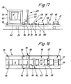
- a chassis is equipped with two complete tube bundle cleaning systems.
- One remains to carry out cleaning work on the undercarriage, the cleaning being carried out essentially in the manner described on the undercarriage by given movement possibilities both of a supporting structure for cleaning tools and for supporting devices of the tube bundle.
- a second complete cleaning device is removably arranged on the undercarriage and is set down next to the undercarriage for carrying out the cleaning work and installed on a predetermined floor area.
- the units required for this, namely a supporting structure for cleaning tools and supporting devices for the tube bundle, are preferred adjustable support feet, which enable exact relative alignment on the given surface.
- the present invention is preferably practiced so that a gate portal with up and down movable cleaning tools for external cleaning and support devices of the type described remain on the chassis, while a frame portal and also, for example, consisting of a flange bracket and a bundle bracket support devices for performing the internal cleaning of Pipes are placed on the floor and set up.
- the frame portal or the lances, lance frames etc. arranged thereon can be designed in the described and claimed embodiment.
- the invention relates to a special embodiment of a lance which is suitable for heavy deposits or dirt in the pipes.
- the lance in question is driven according to the invention rotatably about its own longitudinal axis, thereby fulfilling the function of a drilling lance.
- the rotary drive takes place at the free end of the drilling lance, preferably by means of a hydraulic motor via a gear which can be moved back and forth with the lance.
- a special support is also provided according to the invention.
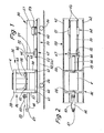
- Such a tube bundle 30 consists of a plurality of parallel-oriented tubes arranged, for example, with a circular outline, which are connected at one end to an end plate 31. This forms a circumferential, protruding flange 32.
- the device for cleaning such tube bundles 30 is on a one-piece drive in the present case Werk 33 mounted, which is designed here as a two-axle car with pneumatic tires 34.
- the entire cleaning system can be transported on the road with the aid of this undercarriage 33.
- well-known supports are advantageously extended to relieve the wheels 34.
- the cleaning device consists in the basic structure of a cleaning unit 35 and a support device for the tube bundle 30, such that the tubes of the same lie essentially horizontally.
- the cleaning unit 35 and the tube bundle 30 are arranged displaceably relative to one another on the undercarriage 33 in order to be able to carry out internal cleaning (cleaning inside the tubes) and external cleaning thereof.
- the cleaning unit 35 consists of a supporting structure in the form of a frame portal 36 for the cleaning tools.
- the frame portal 36 is formed by four upright supports 37 and 38 arranged at corners and upper and lower, transverse or horizontal frames 39 and 40, respectively.
- the lower frame 40 is equipped with wheels 41 which run on rails 42 on the edge of the chassis 33.
- a support structure - in the present case a lifting frame 43 extending in the horizontal plane - can be moved up and down within the frame portal 36.
- the lifting frame 43 is guided in a suitable manner in the area of the supports 37, 38 and can be moved up and down, for example, by a chain drive.
- the lifting frame 43 is the carrier of a cabin K for operating personnel, but also for the cleaning tools.
- the latter is a plurality of spray tubes which extend in the longitudinal direction of the undercarriage 33, namely lances 44, with high-pressure nozzles 45 at their free ends.
- These lances 44 - in the present case three lying side by side in a horizontal plane - are slidably supported and guided in a supporting structure in the form of a lance frame 46 such that they can preferably be inserted together into the tubes of the adjacent or subsequent tube bundle 30.
- the lances 44 or their high-pressure nozzles 45 are moved through the pipes to be cleaned in each case over the entire length, a cleaning liquid (water) escaping at high pressure cleaning the inside of the pipes.
- the lance frame 46 is designed as an elongated, box-shaped supporting structure and is connected to the underside of the lifting frame 43. By moving the same up and down the lance frame and thus the lances 44 can be brought to the required height. At the start of the cleaning process, the lance frame 46 is brought into the required relative position by moving the frame portal 36 or, if necessary, by moving the lance frame 46 relative to the latter.
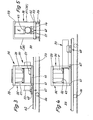
- the tube bundle 30 rests on two support devices, namely a flange bracket 47 and a bundle bracket 48.
- the flange bracket 47 is equipped so that the flange 32 has a stable support.
- two support rollers 49 are provided in the transverse direction at a distance from one another see with longitudinal axes of rotation. The distance between the support rollers 49 can be adjusted by means of an adjusting device (handwheel 50 in FIG. 16). This also makes it possible to adapt to different diameters of the tube bundle 30 or the flange 32.
- the support rollers 49 can be driven in rotation by an (electric) drive motor (not shown in detail) for each support roller 49. By driving the support rollers 49 in the same direction, the entire tube bundle 30 is rotated, so that all tubes are successively brought into a working position for cleaning can.
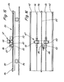
- the bundle bracket 48 is arranged at a distance from the flange bracket 47 and provided with a plurality of support rollers 51. These extend freely rotatably in the longitudinal direction of the tube bundle 30. As can be seen, for example, from FIG. 5, four support rollers 51 with different heights - two each at the same height - are arranged. Smaller tube bundles 30 lie on the inner support rollers 51, while larger tube bundles 30 are carried exclusively by the outer support rollers 51.
- Both support devices ie flange bracket 47 and bundle bracket 48, are equipped with a bogie and can be moved in the longitudinal direction of the bogie 33 with bogies 52 and 53.
- further rails 54 are arranged at a smaller distance from one another and between the rails 42 on the loading surface of the undercarriage 33.
- the optimal relative mobility given by the movability of the aforementioned units enables external cleaning to be carried out with the Cleaning unit 35.
- This is additionally equipped for this with high-pressure spray bars 55 and 56 on the front and rear, namely by arrangement on the lifting frame 43.
- the transverse high-pressure spray bars 55, 56 can be moved over this at a suitable height by moving the frame portal 36 and / or the tube bundle 30 be (position according to Fig. 3).
- the high-pressure spray bars 55, 56 direct cleaning fluid against the outside of the pipes. The entire area of the same can be grasped by rotating the tube bundle 30.
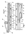
- the lance frame 46 is detachably attached to the frame portal 36 or to the lifting frame 43. It can be removed for external cleaning. The same applies to the transport phase of the facility.
- the lance frame 46 is designed as an elongated hollow box. Within the same, the lances 44 are preferably arranged side by side in a horizontal plane. At one end, the lances 44 telescopically emerge from the lance frame 46.
- each lance 44 is assigned a separate feed chain 57, expediently with a common drive (not shown) for all feed chains 57.
- Each feed chain 57 is with the free back End of the lance 44 connected by a lance carrier 58.
- This is block-shaped and at the same time serves to connect a supply line in the form of a high-pressure hose 59 to the end of the lance 44.
- the lance carrier 58 is a coupling piece. Channels run within it and establish the flow connection.
- the high-pressure hose 59 is brought to the lance 44 in the axial direction thereof.
- the free part of the high-pressure hose 59 is wound onto a hose drum 60, which is arranged here on the top of the lance frame 46.
- the high-pressure hose 59 is guided to and from this hose drum 60 via a hose reel 61 which is arranged in front of the rear end of the lance frame 46 in such a way that the part of the high-pressure hose 59 running to the end of the lance 44 is guided essentially coaxially.
- the ends of the relatively long feed chain 57 are connected to the lance carrier 58, which is extended downwards accordingly. Between the upper and lower run of the feed chain 57 there extends a cross connection between the adjacent lances 44 in the form of a plurality of cross spindles 62.
- Spindle nuts 63 assigned to each lance 44 are mounted on them, which can be moved in the transverse direction by turning the cross spindles 62 and thereby Change the distance between the lances 44.
- the transverse spindles 62 which are spaced apart in the longitudinal direction, can be rotated together in one direction or the other by a common drive (lateral drive chains - not shown). It is expedient the lance 44 lying in the middle is immovable, while the lateral lances 44 are adjustable at a greater or smaller distance from it (see also FIG. 14).
- the cross spindles 62 or their spindle nuts 63 are connected to a separate lance guide. In the exemplary embodiments shown, this is designed as a lance support tube 64 with a square, in particular square, cross section. Such a enveloping lance support tube 64 is assigned to each lance 44. In the exemplary embodiment according to FIG. 6, the spindle nuts 63 are attached to the underside of the lance support tubes 64. A transverse displacement of the spindle nuts 63 also causes a transverse displacement of the lance support tubes 64 and thus the lances 44 themselves.
- the lance support tubes 64 extend within the lance frame 46.
- a guidance of the high-pressure hose 59 which deviates from the proposal of FIG. 6 is provided.
- This connects to the end of the lance 44, namely below it, via a specially designed lance carrier 58. Channels for guiding the cleaning liquid are formed in the appropriately designed lance carrier 58.
- the free part of the high pressure hose 59 is collected, guided and held in a hose trough 65 which is formed below the lance frame 46. This is open in the area in question opposite the hose trough 65, so that the high-pressure hose 59 can be moved between the positions shown, forming a wandering deflection 66.
- the transverse displacement of the lances 44 is also carried out here by corresponding movement of the lance support tubes 64. These are suspended from transverse spindles 62 by spindle nuts 63 attached to the top of each lance support tube 64 and can be displaced transversely by turning them.
- the advance of the lances 44 is also designed differently, namely by a common drive for all lances 44.
- their lance carriers 58 are combined by a common, transversely directed connecting rod 67 and can thus be moved together, for example by laterally arranged chain drives ( Not shown).
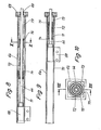
- the lance support tubes 64 are of particular importance since they guide, support and also protect the sensitive lances 44.
- the lance support tubes 64 are arranged side by side in the common lance frame 46.
- the lances 44 each pass through a bore 68 in an end wall 69 of the lance support tube 64. In this area, a slide bearing for the lance 44 is also formed.
- the lance support tube 64 is formed with a continuous slot 70 for the passage of the lance carrier 58 or another suitable coupling of the lance 44 with its drive. This is preferably arranged on the underside (Fig. 10). To prevent the lance 44, which deforms within the lance support tube 64, namely laterally deflecting, from passing through the slot 70, covering or supporting measures are provided.
- the lance support tube 64 enveloping support members, namely support springs.
- These are designed here as spring blocks 71, 72, 73 with a longitudinal dimension which is in each case considerably smaller than the total length of the lance 44 or the lance support tube 64.
- the helical spring blocks 71 envelop the lance 44 with mutual overlap.
- the spring block 72 has a smaller diameter than the adjacent spring blocks 71 and 73. These can therefore partially overlap one another with the support on appropriately shaped guide sleeves 74 and 75.
- the spring blocks 71..73 completely squeezed.
- the guide sleeves 74, 75 lie against each other.
- the lance 44 When the lance 44 is withdrawn and the spring blocks 71..73 are extended, the lance 44 is supported over its entire length, in particular against lateral deflection into the slot 70.
- the use of the spring blocks 71..73 allows large movement amplitudes to be mastered.
- FIGS. 11 and 12 An alternative solution to this topic is shown in FIGS. 11 and 12. Only in the area of the slot 70 is a cover provided, which is designed such that the lance carrier 58 (or another connecting means) can move through the slot 70 over the full length while maintaining the supporting function.
- the slot 70 is covered by an elongated coil spring 76 which extends in a transverse plane approximately over the full length of the lance support tube 64 in a corresponding slot-shaped recess 77.
- the coil spring 76 is designed with an extremely long amplitude and consists of a continuous spring wire.
- Each lance 44 is assigned a separate feed chain 57 here.
- the upper run 78 of this feed chain 57 is guided in the slot 70 of the lance support tube 64. With downward deflections of the lance 44, this support is provided on the upper run 78 of the feed chain 57, it being advantageous that the support with the lance 44 is conveyed without friction.
- the underside of the lance support tube 64 is formed by welded-on square profiles 79, on which the spindle nut 63 is attached for the transverse displacement of the lances 44.
- 14 shows the middle lance 44 which cannot be displaced.
- the cross spindle 62 is here without thread, only rotatably passed through the spindle nut 63. Rotations of the transverse spindle 62 accordingly do not cause any displacement of this spindle nut 63 and thus of the lance 44.
- the spindle nut 63 is provided with a downward projection 80 which has an opening 81 for the passage of the lower run 82 of the feed chain 57. This is guided and supported in the area of its lower run 82. In the region of the upper run 78, transverse support plates 83 are provided here between the supports formed by the spindle nuts 63.
- a traversing chain 85 which is guided in the center and anchored at the ends with chain tensioners 84, is provided.
- the traversing chain 85 is in engagement with a drive wheel 86 on the movable flange bracket 47.
- deflection sprockets 87 arranged offset therefrom, the traversing chain 85 is guided over the drive wheel 86 with sufficient looping and without the risk of lifting off. This is driven in one direction or another by a geared motor 88 attached to the flange bracket 47.
- the flange bracket 47 extends along the traversing chain 85 over the loading area of the undercarriage 33.
- chassis 33 which can be used simultaneously or alternatively on the spot.
- a cleaning device is lifted from the undercarriage 33 and placed at a suitable location on the existing surface.
- Another complete cleaning device remains on the chassis 33.
- a cleaning device for cleaning the outside of the pipes is designed to remain on the chassis 33 and a cleaning device for cleaning the inside is designed to be removable and removable.
- a supporting structure for the outside Cleaning tools in particular for a transversely directed high-pressure spray bar 55 arranged movably.
- a gate portal 89 which is provided with a chassis 91 having four wheels 90.
- the gate portal 89 consists of a transverse, U-shaped frame that is open at the bottom.
- a crossbar 92 for receiving the high-pressure spray bar 55 can be moved up and down there.
- the gate portal 89 is further provided in the area of the chassis 91 with gear boxes 93, in which drive elements (motor, gear) for the lifting movements of the crossbar 92 and for the movement of the gate portal 89 along the running rails 54 of the chassis 33 are accommodated.
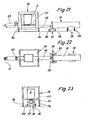
- Supporting devices for the tube bundle 30 in the embodiment already described are assigned to the gate portal 89, namely a flange bracket 47 and a bundle cover 48, each movable. With the aid of these devices, a complete external cleaning of the tube bundle 30 can be carried out on the chassis 33.
- corresponding cleaning units are arranged loosely on the undercarriage 33, namely detachable.
- the support feet 94 are suitably height-adjustable so that an exact positioning of the frame portal 36 on the ground is possible.
- the tube frame 96 consists, for example, of only two inclined support surfaces 97 and 98, which exert a centering effect on the tube bundle 30 regardless of the size thereof.
- Flange frame 95 and tubular frame 96 are each provided with support feet 99 and 100 at the four corners, which also allow height adjustment.
- the frame portal 36 is expediently set down in the rear area of the undercarriage 33.
- the gate portal 89 is arranged adjacent to this. This is followed by flange frame 95 and tubular frame 96. In this arrangement, flange bracket 47 and bundle bracket 48 are located in the front area of chassis 33.
- a special embodiment of the lance 44 can be used for all described exemplary embodiments of cleaning devices.
- This lance 44 is driven to rotate about its own longitudinal axis and thus has the function of a drilling lance 101. It is suitable for removing thick, stuck deposits.
- the free end of the drilling lance 101 is connected to a gear box 102 or enters it a.
- a gearbox in particular a gear transmission 103, is accommodated in the gearbox 102, through which the rotary drive of a hydraulic motor 104 (or another motor) can be transmitted to the drilling lance 101.
- a high-pressure rotary connection 105 of a known type is attached here, which enables the connection of a high-pressure line (high-pressure hose) to the drilling lance 101 for the supply of the cleaning liquid.
- the drilling lance 101 is not guided in a lance support tube 64, but is exposed.
- a plurality of support bearings 106 are provided for support, which are spaced apart from one another in the starting position, but reduce their distance from one another up to the sealing position as the drilling lance 101 extends.
- the support bearings 106 in turn are connected to a feed spindle 107 which rotatably extends within the holder (lance frame) for the drilling lance 101.
- the feed screw 107 is driven by a motor 108 (hydraulic motor) rotating in one direction or the other, which is attached to the lance frame 46 in front of the head end thereof.
- a main spindle nut 109 is also mounted on the feed spindle 107 and is connected to the gearbox 102 and causes the same to be fed to the drilling lance 101.
- the feed spindle 107 is accommodated in an elongated housing 110.
- the drilling lance 101 can also be used in cleaning devices of other embodiments.
Landscapes
- Engineering & Computer Science (AREA)
- Chemical & Material Sciences (AREA)
- Combustion & Propulsion (AREA)
- Mechanical Engineering (AREA)
- General Engineering & Computer Science (AREA)
- Cleaning In General (AREA)
- Cleaning By Liquid Or Steam (AREA)
Abstract
Description
Die Erfindung betrifft eine Einrichtung zum Reinigen von Rohrbündeln mit einer Reinigungsflüssigkeit (Wasser), die durch an den Rohrbündeln entlang- oder in diese eingeführte, zum Beispiel an langgestreckten Rohrstücken (Lanzen) angeordnete Hochdruckdüsen aufgebracht wird.The invention relates to a device for cleaning tube bundles with a cleaning liquid (water), which is applied by high-pressure nozzles arranged along or into the tube bundles, for example arranged on elongated tube pieces (lances).
Die Reinigung von Rohrbündeln spielt besonders in der chemischen bzw. petrochemischen Industrie eine große Rolle. Die betreffenden Rohrbündel sind vorwiegend Teile von Wärmetauschern und ähnlichen Einrichtungen. Die Rohrbündel sind dabei vorwiegend an einem Ende durch eine Endplatte mit seitlich überstehendem Flansch zusammengehalten.The cleaning of tube bundles is particularly important in the chemical and petrochemical industries. The tube bundles in question are predominantly parts of heat exchangers and similar devices. The tube bundles are mainly held together at one end by an end plate with a laterally projecting flange.
Die Reinigung dieser Rohre bzw. Rohrbündel hat in der Regel innen und außen zu erfolgen. Eine Reinigung durch Flüssigkeit (Wasser), die durch Hochdruckdüsen mit erheblicher Energie auf die Rohrbündel auf- bzw.in die einzelnen Rohre eingebracht wird, hat sich als besonders wirksam erwiesen.These pipes or pipe bundles must generally be cleaned inside and outside. A cleaning through Liquid (water), which is applied to the tube bundle or into the individual tubes by high-pressure nozzles with considerable energy, has proven to be particularly effective.
Für die Innenreinigung der Rohre finden Rohrstücke Verwendung, sogenannte Lanzen, an deren Arbeitsende eine Hochdruckdüse angeordnet ist. Die Lanzen werden in die zu reinigenden Rohre eingeführt.Pieces of pipe, so-called lances, are used for the internal cleaning of the pipes, at the working end of which a high-pressure nozzle is arranged. The lances are inserted into the pipes to be cleaned.
Die Reinigung von Rohrbündeln unter Verwendung von Hochdruckdüsen, insbesondere mit Lanzen, ist bisher überwiegend manuell ausgeführt worden. Bekannt sind aber auch bereits stationär montierte, umfängliche und aufwendige Reinigungsanlagen, in denen die Lanzen mechanisch bewegt werden.The cleaning of tube bundles using high-pressure nozzles, in particular with lances, has hitherto mainly been carried out manually. But also stationary, extensive and complex cleaning systems are known, in which the lances are moved mechanically.
Der Erfindung liegt die Aufgabe zugrunde, eine Einrichtung zur Reinigung von Rohrbündeln vorzuschlagen, die im Aufbau und in der Handhabung einfach ist und darüber hinaus einen universellen Einsatz in der Praxis gewährleistet.The invention has for its object to propose a device for cleaning tube bundles, which is simple in construction and handling and also ensures universal use in practice.
Zur Lösung dieser Aufgabe ist die erfindungsgemäße Reinigungsanlage dadurch gekennzeichnet, daß ein Tragwerk (Rahmenportal) für eine Gruppe von Lanzen sowie Stützvorrichtungen für wenigstens ein Rohrbündel auf einem Fahrwerk angeordnet und relativ zueinander bewegbar sind.To achieve this object, the cleaning system according to the invention is characterized in that a supporting structure (frame portal) for a group of lances and supporting devices for at least one tube bundle are arranged on a trolley and are movable relative to one another.
Ein wesentlicher Gedanke der Erfindung besteht demnach in der Mobilität einer kompletten Reinigungsanlage für Rohrbündel. Die erforderlichen Aggregate sind zu diesem Zweck auf einem auf Straße oder Schiene verfahrbaren Tragwerk angeordnet, und zwar so, daß alle Aggregate relativ zueinander verschiebbar sind. Dadurch ist auf engstem Raum eine volle Reinigung der Rohrbündel sowohl im Inneren der einzelnen Rohre wie auch außen möglich.An essential idea of the invention is therefore the mobility of a complete cleaning system for tube bundles. For this purpose, the necessary units are arranged on a structure that can be moved on road or rail, and in such a way that all Aggregates are displaceable relative to one another. This enables full cleaning of the tube bundle in the interior of the individual tubes as well as on the outside in a confined space.
In der einfachsten Ausführung ist auf dem Fahrwerk ein dreidimensionales Tragwerk in Gestalt eines Rahmenportals verfahrbar (auf Schienen) angeordnet. Dieses nimmt ein Traggestell (Lanzenrahmen) zur Halterung und Führung einer Mehrzahl von Lanzen auf, derart, daß diese in der Ebene bzw. in Richtung der Längsachse der Rohre verschoben werden können. Der Lanzenrahmen ist dabei zweckmässigerweise sowohl der Höhe nach wie auch in Längsrichtung verschiebbar am Rahmenportal gelagert. Des weiteren gehören zu dieser Einrichtung mindestens eine, vorzug-s-weise aber zwei im Abstand voneinander angeordnete Stützvorrichtungen für das zu reinigende Rohrbündel. Diese Stützvorrichtungen sind ebenfalls verfahrbar (auf Schienen) auf dem Fahrwerk angeordnet. Es handelt sich dabei vorzugsweise umI· einen Flanschbock und einen Bündelbock. Der erstgenannte ist so ausgebildet, daß der den Reinigungswerkzeugen zugekehrte Flansch des Rohrbündels auf Rollen Auflage findet. Der Bündelbock ist mit einer Mehrzahl von Stützwalzen zur Auflagerung der Rohre versehen. Mindestens eine dieser Stützvorrichtungen ist nach einem weiteren Vorschlag der Erfindung mit drehbar angetriebenen Auflagern für das Rohrbündel versehen, insbesondere die Stützrollen des Flanschbocks, um eine Drehung des Rohrbündels um die edgene Längsachse durchführen zu können.In the simplest version, a three-dimensional supporting structure in the form of a frame portal is arranged on the running gear (on rails). This receives a support frame (lance frame) for holding and guiding a plurality of lances, such that they can be moved in the plane or in the direction of the longitudinal axis of the tubes. The lance frame is expediently mounted on the frame portal both in height and in the longitudinal direction. Furthermore, this device includes at least one, but preferably two, spaced-apart supporting devices for the tube bundle to be cleaned. These support devices are also movable (on rails) arranged on the chassis. These are preferably a flange bracket and a bundle bracket. The former is designed so that the flange of the tube bundle facing the cleaning tools is supported on rollers. The bundle block is provided with a plurality of support rollers for supporting the tubes. According to a further proposal of the invention, at least one of these support devices is provided with rotatably driven supports for the tube bundle, in particular the support rollers of the flange bracket, in order to be able to rotate the tube bundle about the edgen longitudinal axis.
Weitere Merkmale der Erfindung beziehen sich auf die Ausgestaltung des Lanzenrahmens sowie auf die Ausgestaltung, Lagerung, Führung und Versorgung der Lanzen mit Reinigungsflüssigkeit. Die erfindungsgemäße Ausführung ist derart getroffen, daß die erforderlichen Bewegungen der Lanzen selbsttätig bzw. mechanisch, jedenfalls ohne manuellen Eingriff, ablaufen.Further features of the invention relate to the design of the lance frame and to the design, storage, guidance and supply of the lances with cleaning fluid. The embodiment according to the invention is the art that the required movements of the lances run automatically or mechanically, at least without manual intervention.
Das Rahmenportal ist weiterhin mit Reinigungswerkzeugen für die Durchführung der Außenreinigung, nämlich einem Spritzbalken oder einzelnen Hochdruckdüsen versehen. Diese sind ebenfalls der Höhe nach verschiebbar angeordnet, so daß durch Relativbewegung des Rahmenportals und des Rohrbündels zueinander alternativ oder gleichzeitig eine Außen- und Innenreinigung durchgeführt werden können.The frame portal is also provided with cleaning tools for carrying out external cleaning, namely a spray bar or individual high-pressure nozzles. These are also arranged to be displaceable in height, so that an external and internal cleaning can alternatively or simultaneously be carried out by moving the frame portal and the tube bundle relative to one another.
Zur optimalen Raumausnutzung sind die Stützvorrichtungen für das Rohrbündel in Längsrichtung auf dem Fahrwerk verschiebbar.For optimal use of space, the support devices for the tube bundle can be moved in the longitudinal direction on the chassis.
Der Gedanke der Mobilität einer kompletten Reinigungs- anlage kommt in besonderem Maße bei einem weiterentwickelten Ausführungsbeispiel der Erfindung zum Tragen. Bei diesem ist ein Fahrwerk mit zwei kompletten Rohrbündel-Reinigungsanlagen ausgestattet. Die eine bleibt zur Durchführung von Reinigungsarbeiten auf dem Fahrwerk, wobei durch gegebene Bewegungsmöglichkeiten sowohl eines Tragwerks für Reinigungswerkzeuge als auch für Stützvorrichtungen des Rohrbündels die Reinigung im wesentlichen in der beschriebenen Weise auf dem Fahrwerk durchgeführt wird. Eine zweite komplette Reinigungseinrichtung ist abnehmbar auf dem Fahrwerk angeordnet und wird zur Durchführung der Reinigungsarbeiten neben diesem abgesetzt und auf vorgegebener Bodenfläche installiert. Die hierfür erforderlichen Aggregate, nämlich ein Tragwerk für Reinigungswerkzeuge und Stützvorrichtungen für das Rohrbündel, sind mit vorzugsweise justierbaren Stützfüßen ausgerüstet, die eine exakte Relativausrichtung auf dem jeweils vorgegebenen Untergrund ermöglichen.The idea of mobility of a complete cleaning system is particularly relevant in a further developed embodiment of the invention. In this, a chassis is equipped with two complete tube bundle cleaning systems. One remains to carry out cleaning work on the undercarriage, the cleaning being carried out essentially in the manner described on the undercarriage by given movement possibilities both of a supporting structure for cleaning tools and for supporting devices of the tube bundle. A second complete cleaning device is removably arranged on the undercarriage and is set down next to the undercarriage for carrying out the cleaning work and installed on a predetermined floor area. The units required for this, namely a supporting structure for cleaning tools and supporting devices for the tube bundle, are preferred adjustable support feet, which enable exact relative alignment on the given surface.
Die vorliegende Erfindung wird vorzugsweise so praktiziert, daß ein Torportal mit auf- und abbewegbaren Reinigungswerkzeugen für die Außenreinigung und Stützvorrichtungen der beschriebenen Art auf dem Fahrwerk bleiben, während ein Rahmenportal und ebenfalls zum Beispiel aus einem Flanschbock und einem Bündelbock bestehende Stützvorrichtungen zur Durchführung der Innenreinigung der Rohre auf dem Boden abgesetzt und eingerichtet werden. Das Rahmenportal bzw. die daran angeordneten Lanzen, Lanzenrahmen etc. können in der beschriebenen und beanspruchten Ausführung ausgebildet sein.The present invention is preferably practiced so that a gate portal with up and down movable cleaning tools for external cleaning and support devices of the type described remain on the chassis, while a frame portal and also, for example, consisting of a flange bracket and a bundle bracket support devices for performing the internal cleaning of Pipes are placed on the floor and set up. The frame portal or the lances, lance frames etc. arranged thereon can be designed in the described and claimed embodiment.
Weiterhin bezieht sich die Erfindung auf eine besondere Ausführung einer Lanze, die für starke Ablagerungen oder Verschmutzungen in den Rohren geeignet ist. Die betreffende Lanze ist erfindungsgemäß um die eigene Längsachse drehbar angetrieben, erfüllt dadurch die Funktion einer Bohrlanze. Der Drehantrieb erfolgt am freien Ende der Bohrlanze, vorzugsweise durch einen Hydraulikmotor über ein mit der Lanze hin- und herverfahrbares Getriebe. Bei dieser Bohrlanze ist darüber hinaus erfindungsgemäß eine besondere Abstützung vorgesehen.Furthermore, the invention relates to a special embodiment of a lance which is suitable for heavy deposits or dirt in the pipes. The lance in question is driven according to the invention rotatably about its own longitudinal axis, thereby fulfilling the function of a drilling lance. The rotary drive takes place at the free end of the drilling lance, preferably by means of a hydraulic motor via a gear which can be moved back and forth with the lance. In this drilling lance, a special support is also provided according to the invention.
Weitere Merkmale der Erfindung sind Gegenstand von Unteransprüchen.Further features of the invention are the subject of dependent claims.
Nachfolgend werden Ausführungsbeispiele und Einzelheiten der Erfindung anhand der Zeichnungen näher erläutert. Es zeigen:
- Fig. 1 eine verfahrbare Rohrbündel-Reinigungs-Einrichtung in schematischer Seitenansicht,
- Fig. 2 einen schematischen Grundriß der Einrichtung gemäß Fig. 1,
- Fig. 3 die Einrichtung gemäß Fig. 1 in einer Stellung für die Außenreinigung eines Rohrbündels, in Seitenansicht,
- Fig. 4 die Anlage gemäß Fig. 1 bis 3 in einer gegenüber Fig. 3 nochmals veränderten Relativstellung bei der Außenreinigung eines Rohrbündels, ebenfalls in Seitenansicht,
- Fig. 5 die Einrichtung gemäß Fig. 1 bis 4 während der Außenreinigung (Stellung gemäß Fig. 4) in Vorder- bzw. Stirnansicht,
- Fig. 6 eine Einzelheit eines Lanzenrahmens im Längsschnitt bei vergrößertem Maßstab,
- Fig. 7 eine Darstellung entsprechend Fig. 6 für ein anderes Ausführungsbeispiel der Ausbildung eines Lanzenrahmens,
- Fig. 8 eine Einzelheit über die Führung und Stützung einer Lanze im Längsschnitt,
- Fig. 9 die Einzelheit gemäß Fig. 8 bei veränderter Relativposition der Lanze,
- Fig. 10 einen Querschnitt X-X in Fig. 8, bei vergrößertem Maßstab,
- Fig. 11 ein anderes Ausführungsbeispiel für die Führung einer Lanze im Horizontalschnitt bzw. Grundriß,
- Fig. 12 einen Querschnitt XII-XII in Fig. 11, bei vergrößertem Maßstab,
- Fig. 13 ein weiteres Ausführungsbeispiel für die Gestaltung eines Lanzenrahmens bzw. den Antrieb einer Lanze im Längsschnitt,
- Fig. 14 einen Querschnitt zu der Ausführung gemäß Fig. 13 bei vergrößertem Maßstab und um 90° versetzt,
- Fig. 15 ein Fahrwerk in Seitenansicht mit Einzelheiten über die Verfahrbarkeit einer Stützvorrichtung (Flanschbock) für ein Rohrbündel,
- Fig. 16 die Vorrichtung gemäß Fig. 15 im Grundriß,
- Fig. 17 eine Rohrbündel-Reinigungs-Einrichtung mit mehreren, nämlich zwei kompletten Reinigungs-Einrichtungen in fahrbarem Zustand, in Seitenansicht,
- Fig. 18 das Ausführungsbeispiel gemäß Fig. 17 im Grundriß,
- Fig. 19 die Einrichtung gemäß Fig. 17 und 18 in der Anordnung für die Außenreinigung eines Rohrbündels in schematischer Seitenansicht,
- Fig. 20 eine Vorder- bzw. Stirnansicht zu der Anordnung in Fig. 19,
- Fig. 21 die als Teil der Einrichtung gemäß Fig. 17 und 18 angeordnete Einrichtung für die Innenreinigung von Rohren in schematischer Seitenansicht,
- Fig. 22 einen Grundriß zu Fig. 21,
- Fig. 23 eine Vorder- bzw. Stirnansicht der Einrichtung gemäß Fig. 21 und 22,
- Fig. 24. eine (drehend angetriebene) Bohrlanze mit Halterung und Führung in Seitenansicht bzw. im Längsschnitt,
- Fig. 25 einen Querschnitt durch die Vorrichtung gemäß Fig. 24 in der Ebene XXV-XXV.
- 1 is a movable tube bundle cleaning device in a schematic side view,
- 2 shows a schematic plan view of the device according to FIG. 1,
- 3 shows the device according to FIG. 1 in a position for the external cleaning of a tube bundle, in a side view,
- 4 shows the system according to FIGS. 1 to 3 in a relative position, again changed compared to FIG. 3, for the external cleaning of a tube bundle, likewise in a side view,
- 5 shows the device according to FIGS. 1 to 4 during external cleaning (position according to FIG. 4) in front and end view,
- 6 shows a detail of a lance frame in longitudinal section on an enlarged scale,
- 7 is an illustration corresponding to FIG. 6 for another embodiment of the formation of a lance frame,
- 8 is a detail on the guidance and support of a lance in longitudinal section,
- 9 shows the detail according to FIG. 8 with a changed relative position of the lance,
- 10 shows a cross section XX in FIG. 8, on an enlarged scale,
- 11 shows another embodiment for guiding a lance in horizontal section or plan view,
- 12 is a cross section XII-XII in Fig. 11, on an enlarged scale,
- 13 shows a further exemplary embodiment for the design of a lance frame or the drive of a lance in longitudinal section,
- 14 is a cross section to the embodiment of FIG. 13 on an enlarged scale and offset by 90 °,
- 15 a chassis in side view with details of the movability of a support device (flange bracket) for a tube bundle,
- 16 shows the device according to FIG. 15 in plan view,
- 17 is a side view of a tube bundle cleaning device with several, namely two complete cleaning devices in a mobile state,
- 18 shows the exemplary embodiment according to FIG. 17 in plan view,
- 19 shows the device according to FIGS. 17 and 18 in the arrangement for the external cleaning of a pipe bundle in a schematic side view,
- 20 is a front or end view of the arrangement in FIG. 19,
- 21 is a schematic side view of the device for the internal cleaning of pipes arranged as part of the device according to FIGS. 17 and 18,
- 22 is a plan view of FIG. 21,
- 23 shows a front and end view of the device according to FIGS. 21 and 22,
- 24 a (rotatingly driven) drilling lance with holder and guide in side view or in longitudinal section,
- 25 shows a cross section through the device according to FIG. 24 in the plane XXV-XXV.
Die in den Zeichnungen dargestellten Ausführungsbeispiele und Einzelheiten von Reinigungs-Einrichtungen sind für die Reinigung von Rohrbündeln 30. bestimmt. Ein derartiges Rohrbündel 30 besteht aus einer Mehrzahl von beispielsweise mit kreisförmigem Umriß angeordneten, parallelgerichteten Rohren, die an einem Ende mit einer Endplatte 31 verbunden sind. Diese bildet einen ringsherumlaufenden, überstehenden Flansch 32.The exemplary embodiments and details of cleaning devices shown in the drawings are intended for cleaning tube bundles 30. Such a
Die Einrichtung zum Reinigen derartiger Rohrbündel 30 ist auf einem im vorliegenden Fall einteiligen Fahrwerk 33 montiert, das hier als zweiachsiger Wagen mit luftbereiften Rädern 34 ausgebildet ist. Die gesamte Reinigungs-Anlage kann mit Hilfe dieses Fahrwerks 33 auf der Straße transportiert werden. An Ort und Stelle des Einsatzes werden zweckmäßigerweise seitlich bekannte Stützen ausgefahren zur Entlastung der.Räder 34.The device for cleaning such tube bundles 30 is on a one-piece drive in the
Die Reinigungs-Einrichtung besteht im Grundaufbau aus einem Reinigungsaggregat 35 und einer Stützvorrichtung für das Rohrbündel 30, derart, daß die Rohre desselben im wesentlichen horizontalgerichtet liegen. Das Reinigungsaggregat 35 und das Rohrbündel 30 sind relativ zueinander verschiebbar auf dem Fahrwerk 33 angeordnet, um eine Innenreinigung (Reinigunginnerhalb der Rohre) und eine Außenreinigung derselben durchführen zu können.The cleaning device consists in the basic structure of a
Bei dem Ausführungsbeispiel der Fig. 1 bis 5 besteht das Reinigungsaggregat 35 aus einem Tragwerk in Gestalt eines Rahmenportals 36 für die Reinigungswerkzeuge. Das Rahmenportal 36 wird durch vier an Ecken angeordnete aufrechte Stützen 37 und 38 sowie obere und untere, quer- bzw. horizontalgerichtete Rahmen 39 bzw. 40 gebildet. Der untere Rahmen 40 ist mit Laufrädern 41 ausgestattet, die auf Laufschienen 42 am Rand des Fahrwerks 33 ablaufen.In the embodiment of FIGS. 1 to 5, the
Innerhalb des Rahmenportals 36 ist ein Tragwerk - im vorliegenden Fall ein sich in horizontaler Ebene erstreckender Hubrahmen 43 - auf- und abbewegbar. Der Hubrahmen 43 ist in geeigneter Weise im Bereich der Stützen 37, 38 geführt und beispielsweise durch Kettentrieb auf- und abbewegbar.A support structure - in the present case a lifting
Der Hubrahmen 43 ist Träger einer Kabine K für Bedienungspersonal, aber auch für die Reinigungswerkzeuge. Bei J letzteren handelt es sich einmal um mehrere sich in Längsrichtung des Fahrwerks 33 erstreckende Spritzrohre, nämlich Lanzen 44,mit Hochdruckdüsen 45 an ihren freien Enden. Diese Lanzen 44 - im vorliegenden Fall drei in horizontaler Ebene nebeneinanderliegende - sind in einem Tragwerk in Gestalt eines Lanzenrahmens 46 verschiebbar gelagert und geführt, derart, daß sie vorzugsweise gemeinsam in die Rohre des benachbarten bzw. anschließenden Rohrbündels 30 eingeführt werden können. Die Lanzen 44 bzw. deren Hochdruckdüsen 45 werden durch die jeweils zu reinigenden Rohre über die gesamte Länge hindurchbewegt, wobei eine mit Hochdruck austretende Reinigungsflüssigkeit (Wasser) die Innenseite der Rohre reinigt.The lifting
Der Lanzenrahmen 46 ist als langgestrecktes, kastenförmiges Tragwerk ausgebildet und mit der Unterseite des Hubrahmens 43 verbunden. Durch Auf- und Abwärtsbewegen desselben kann der Lanzenrahmen und können demnach die Lanzen 44 auf die jeweils erforderliche Höhe gebracht werden. Bei Beginn des Reinigungsvorgangs wird der Lanzenrahmen 46 durch Verfahren des Rahmenportals 36 oder gegebenenfalls durch Verschieben des Lanzenrahmens 46 relativ zu diesem in die erforderliche Relativposition gebracht.The
Das Rohrbündel 30 liegt auf zwei Stützvorrichtupgen auf, nämlich einem Flanschbock 47 und einem Bündelbock 48. Der Flanschbock 47 ist so ausgerüstet, daß der Flansch 32 stabile Auflage hat. Bei dem gezeigten Ausführungsbeispiel sind zwei in Querrichtung mit Abstand voneinander angeordnete Stützrollen 49 vorgesehen mit längsgerichteten Drehachsen. Die Stützrollen 49 sind durch eine Stelleinrichtung (Handrad 50 in Fig. 16) hinsichtlich ihres Abstandes voneinander einstellbar. Dadurch ist auch eine Anpassung an unterschiedliche Durchmesser des Rohrbündels 30 bzw. des Flansches 32 möglich. Des weiteren sind die Stützrollen 49 rotierend antreibbar durch einen im einzelnen nicht dargestellten (elektrischen) Antriebsmotor für jede Stützrolle 49. Durch gleichgerichteten Antrieb der Stützrollen 49 wird das gesamte Rohrbündel 30 gedreht, so daß nacheinander alle Rohre in eine arbeitsgerechte Position für die Reinigung gebracht werden können.The
Der Bündelbock 48 ist mit Abstand vom Flanschbock 47 angeordnet und mit einer Mehrzahl von Stützwalzen 51 versehen. Diese erstrecken sich frei drehbar in Längsrichtung des Rohrbündels 30. Wie beispielsweise aus Fig. 5 ersichtlich, sind vier Stützwalzen 51 mit unterschiedlichen Höhen - je zwei auf gleicher Höhe - angeordnet. Kleinere Rohrbündel 30 liegen auf den inneren Stützwalzen 51 auf, während größere Rohrbündel 30 ausschließlich durch die außenliegenden Stützwalzen 51 getragen werden.The
Beide Stützvorrichtungen, also Flanschbock 47 und Bündelbock 48, sind mit einem Laufgestell ausgerüstet und mit Laufrädern 52 sowie 53 auf dem Fahrwerk 33 in Längsrichtung desselben verfahrbar. Zu diesem Zweck sind weitere Laufschienen 54 mit geringerem Abstand voneinander und zwischen den Laufschienen 42 auf der Ladefläche des Fahrwerks 33 angeordnet.Both support devices,
Die durch die Verfahrbarkeit der vorgenannten Aggregate gegebene optimale Relativbeweglichkeit ermöglicht die Durchführung auch von Außenreinigungen mit dem Reinigungsaggregat 35. Dieses ist hierfür zusätzlich mit Hochdruckspritzbalken 55 und 56 an Vorder- und Rückseite ausgerüstet, nämlich durch Anordnung am Hubrahmen 43. Die quergerichteten Hochdruckspritzbalken 55, 56 können in geeigneter Höhe durch Verfahren des Rahmenportals 36 und/oder des Rohrbündels 30 über dieses hinwegbewegt werden (Position gemäß Fig.3). Die Hochdruckspritzbalken 55, 56 richten dabei Reinigungsflüssigkeit gegen die Außenseite der Rohre. Durch Drehen des Rohrbündels 30 kann der gesamte Bereich desselben erfaßt werden.The optimal relative mobility given by the movability of the aforementioned units enables external cleaning to be carried out with the
Der Lanzenrahmen 46 ist bei diesem Ausführungsbeispiel lösbar am Rahmenportal 36 bzw. am Hubrahmen 43 angebracht. Er kann für die Durchführung der Außenreinigung abgenommen werden. Gleiches gilt für die Transportphase der Einrichtung.In this exemplary embodiment, the
Der Lanzenrahmen 46 ist als langgestreckter Hohlkasten ausgebildet. Innerhalb desselben sind die Lanzen 44 vorzugsweise in einer horizontalen Ebene nebeneinanderliegend angeordnet. An einem Ende treten die Lanzen 44 durch Vorschub teleskopartig aus dem Lanzenrahmen 46 aus.The
Bei dem Ausführungsbeispiel der Fig. 6 werden die Lanzen 44 durch einen unterhalb des Lanzenrahmens 46 angeordneten Endlosförderer, nämlich durch eine Vorschubkette 57, hin- und herbewegt. Bei dem hder angesprochenen Ausführungsbeispiel ist jeder Lanze 44 eine gesonderte Vorschubkette 57 zugeordnet, zweckmäßigerweise mit einem gemeinsamen Antrieb (nicht gezeigt)für alle Vorschubketten 57.6, the
Jede Vorschubkette 57 ist mit dem freien, rückseitigen Ende der Lanze 44 durch einen Lanzenträger 58 verbunden. Dieser ist klotzförmig ausgebildet und dient zugleich dem Anschluß einer Versorgungsleitung in Gestalt eines Hochdruckschlauchs 59 an das Ende der Lanze 44. Der Lanzenträger 58 ist insoweit Kupplungsstück. Innerhalb desselben verlaufen Kanäle, die die Strömungsverbindung herstellen.Each
Bei dem Ausführungsbeispiel der Fig. 6 wird der Hochdruckschlauch 59 jeweils in Axialrichtung der Lanze 44 an diese herangeführt. Der je nach Relativstellung derselben freie Teil des Hochdruckschlauchs 59 wird auf eine Schlauchtrommel 60 aufgewickelt, die hier auf der Oberseite des Lanzenrahmens 46 angeordnet ist. Der Hochdruckschlauch 59 wird von und zu dieser Schlauchtrommel 60 über eine Schlauchrolle 61 geleitet, die vor dem rückseitigen Ende des Lanzenrahmens 46 so angeordnet ist, daß der zum Ende der Lanze 44 ablaufende Teil des Hochdruckschlauchs 59im wesentlichen gleichachsig geführt ist.In the embodiment of FIG. 6, the high-
Die verhältnismäßig lange Vorschubkette 57 ist mit ihren Enden an den nach unten entsprechend verlängerten Lanzenträger 58 angeschlossen. Zwischen dem oberen und unteren Trum der Vorschubkette 57 erstreckt sich hier eine Querverbindung zwischen den benachbarten Lanzen 44 in Gestalt von mehreren Querspindeln 62. Auf diesen sind jeder Lanze 44 zugeordnete Spindelmuttern 63 gelagert, die durch Drehen der Querspindeln 62 in Querrichtung bewegbar sind und dadurch den Abstand der Lanzen 44 voneinander verändern. Die mit Abständen in Längsrichtung voneinander angeordneten Querspindeln 62 sind durch einen gemeinsamen Antrieb (seitliche Antriebsketten - nicht gezeigt) gemeinsam in der einen oder anderen Richtung drehbar. Zweckmäßigerweise ist die in der Mitte liegende Lanze 44 unverschiebbar, während die seitlichen Lanzen 44 auf größeren oder kleineren Abstand von dieser verstellbar sind (siehe auch Fig. 14).The ends of the relatively
Die Querspindeln 62 bzw. deren Spindelmuttern 63 sind mit einer gesonderten Lanzenführung verbunden. Diese ist bei den gezeigten Ausführungsbeispielen als Lanzenstützrohr 64 ausgebildet mit einem viereckigen, insbesondere quadratischen Querschnitt. Jeder Lanze 44 ist ein derartiges, umhüllendes Lanzenstützrohr 64 zugeordnet. Die Spindelmuttern 63 sind bei dem Ausführungsbeispiel gemäß Fig. 6 an der Unterseite der Lanzenstützrohre 64 angebracht. Eine Querverschiebung der Spindelmuttern 63 bewirkt zugleich eine Querverschiebung der Lanzenstützrohre 64 und damit der Lanzen 44 selbst. Die Lanzenstützrohre 64 erstrecken sich innerhalb des Lanzenrahmens 46.The cross spindles 62 or their
Bei dem Ausführungsbeispiel gemäß Fig. 7 ist eine von dem Vorschlag der Fig. 6 abweichende Führung des Hochdruckschlauchs 59 vorgesehen. Dieser schließt über einen besonders ausgebildeten Lanzenträger 58 an das Ende der Lanze 44 an, nämlich unterhalb derselben. In dem entsprechend ausgebildeten Lanzenträger 58 werden Kanäle für die Führung der Reinigungsflüssigkeit gebildet. Der freie Teil des Hochdruckschlauchs 59 wird in einer Schlauchwanne 65 aufgefangen, geführt und gehalten, die unterhalb des Lanzenrahmens 46 gebildet ist. Dieser ist in dem betreffenden Bereich gegenüber der Schlauchwanne 65 offen, so daß der Hochdruckschlauch 59 unter Bildung einer wandernden Umlenkung 66 zwischen den gezeigten Positionen bewegbar ist.In the embodiment according to FIG. 7, a guidance of the high-
Die Querverschiebbarkeit der Lanzen 44 wird auch hier durch entsprechende Bewegung der Lanzenstützrohre 64 vollzogen. Diese sind hier durch an der Oberseite eines jeden Lanzenstützrohrs 64 angebrachte Spindelmuttern 63 an Querspindeln 62 aufgehängt und durch Drehen derselben querverschiebbar.The transverse displacement of the
Auch der Vorschub der Lanzen 44 ist hier abweichend ausgebildet, nämlich durch einen gemeinsamen Antrieb für alle Lanzen 44. Deren Lanzenträger 58 sind zu diesem Zweck durch eine gemeinsame, quergerichtete Verbindungsstange 67 zusammengefaßt und können dadurch gemeinsam bewegt werden, zum Beispiel durch seitlich angeordnete Kettentriebe (nicht gezeigt).The advance of the
Von besonderer Bedeutung sind die Lanzenstützrohre 64, da sie die empfindlichen Lanzen 44 führen, stützen und auch schützen. Die Lanzenstützrohre 64 sind nebeneinanderliegend in dem gemeinsamen Lanzenrahmen 46 angeordnet. Die Lanzen 44 treten jeweils durch eine Bohrung 68 in einer Endwandung 69 des Lanzenstützrohrs 64 hindurch. In diesem Bereich wird zugleich ein Gleitlager für die Lanze 44 gebildet.The
Für den Durchtritt des Lanzenträgers 58 bzw. einer anderen geeigneten Kupplung der Lanze 44 mit deren Antrieb ist das Lanzenstützrohr 64 mit einem durchgehenden Schlitz 70 ausgebildet. Dieser ist vorzugsweise an der Unterseite angeordnet (Fig. 10). Um zu verhindern, daß die innerhalb des Lanzenstützrohrs 64 sich verformende, nämlich seitlich auslenkende Lanze 44 etwa durch den Schlitz 70 hindurchtritt, sind abdeckende bzw. abstützende Maßnahmen vorgesehen.The
Bei dem Ausführungsbeispiel gemäß Fig. 8 bis 10 sind innerhalb des Lanzenstützrohrs 64 umhüllende Stützorgane angeordnet, nämlich Stützfedern. Diese sind hier als Federblöcke 71, 72, 73 mit einer Längsabmessung ausgebildet, die jeweils erheblich kleiner ist als die Gesamtlänge der Lanze 44 bzw. des Lanzenstützrohrs 64. Die schraubenförmigen Federblöcke 71 umhüllen die Lanze 44 mit wechselseitiger Überdeckung. Der Federblock 72 hat zu diesem Zweck einen geringeren Durchmesser als die benachbarten Federblöcke 71 und 73. Diese können deshalb einander teilweise übergreifen unter Abstützung auf entsprechend geformten Führungshülsen 74 und 75. Bei ausgefahrener Lanze 44 (Fig. 9) sind die Federblöcke 71..73 vollständig zusammengedrückt. Die Führungshülsen 74, 75 liegen aneinander. Bei zurückgezogener Lanze 44 und ausgedehnten Federblöcken 71..73 wird die Lanze 44 auf voller Länge abgestützt, insbesondere gegen seitliches Ausweichen in den Schlitz 70. Durch den Einsatz der Federblöcke 71..73 können große Bewegungsamplituden beherrscht werden.8 to 10 are in the embodiment arranged within the
Eine Alternativlösung zu diesem Thema ist in Fig. 11 und 12 gezeigt. Lediglich im Bereich des Schlitzes 70 ist hier eine Abdeckung desselben vorgesehen, die so ausgebildet ist, daß unter Aufrechterhaltung der abstützenden Funktion der Lanzenträger 58 (oder ein anderes Verbindungsmittel) durch den Schlitz 70 über die volle Länge wandern kann. Zu diesem Zweck ist der Schlitz 70 durch eine langgestreckte Schlangenfeder 76 abgedeckt, die sich in einer Querebene annähernd über die volle Länge des Lanzenstützrohrs 64 in einer entsprechenden schlitzförmigen Ausnehmung 77 erstreckt. Die Schlangenfeder 76 ist mit einer äußerst langen Amplitude wellenförmig ausgebildet und besteht aus einem durchgehenden Federdraht. Bei dieser Lösung werden Auslenkungen der Lanze 44 innerhalb des Lanzenstützrohrs 64 unter Anlage an den Wandungen desselben bzw. an der Schlangenfeder 76 in Kauf genommen.An alternative solution to this topic is shown in FIGS. 11 and 12. Only in the area of the
Auch das Ausführungsbeispiel gemäß Fig. 13 und 14 befaßt sich mit dem vorstehend angesprochenen Thema. Hier ist jeder Lanze 44 eine gesonderte Vorschubkette 57 zugeordnet. Der Obertrum 78 dieser Vorschubkette 57 ist in dem Schlitz 70 des Lanzenstützrohrs 64 verlaufend geführt. Bei nach unten gerichteten Auslenkungen der Lanze 44 erhält diese Auflage auf dem Obertrum 78 der Vorschubkette 57, wobei vorteilhaft ist, daß dabei die Abstützung mit der Lanze 44 reibungsfrei gefördert wird.The exemplary embodiment according to FIGS. 13 and 14 also deals with the topic discussed above. Each
Die Unterseite des Lanzenstützrohrs 64 wird bei diesem Ausführungsbeispiel durch angeschweißte Vierkantprofile 79 gebildet, an denen die Spindelmutter 63 für die Querverschiebung der Lanzen 44 angebracht ist. In Fig. 14 wird die mittlere, nicht zu verschiebende Lanze 44 gezeigt. Die Querspindel 62 ist hier ohne Gewinde, lediglich drehbar durch die Spindelmutter 63 hindurchgeführt. Drehungen der Querspindel 62 bewirken demnach keine Verschiebungen dieser Spindelmutter 63 und damit der Lanze 44.In this exemplary embodiment, the underside of the
Die Spindelmutter 63 ist mit einem nach unten weisenden Ansatz 80 versehen, der eine Öffnung 81 für den Durchtritt des Untertrums 82 der Vorschubkette 57 aufweist. Diese wird so im Bereich ihres Untertrums 82 geführt und gestützt. Im Bereich des Obertrums 78 sind hier zwischen den durch die Spindelmuttern 63 gebildeten Abstützungen quergerichtete Stützplatten 83 vorgesehen.The
Fig. 15 und 16 zeigen eine Lösung für eine präzise, spielfreie Bewegung des bereits beschriebenen Flanschbocks 47 in Längsrichtung des Fahrwerks 33 auf diesem. Hierfür ist bei dem gezeigten Ausführungsbeispiel eine mittig geführte, an den Enden mit Kettenspannern 84 verankerte Traversierkette 85 vorgesehen. Die Traversierkette 85 steht in Eingriff mit einem Antriebsrad 86 am verfahrbaren Flanschbock 47. Mit Hilfe von versetzt hierzu angeordneten Umlenkkettenrädern 87 wird die Traversierkette 85 mit ausreichender Umschlingung und ohne die Gefahr des Abhebens über das Antriebsrad 86 geführt. Dieses wird in der einen oder anderen Richtung durch einen mit am Flanschbock 47 angebrachten Getriebemotor 88 angetrieben. Der Flanschbock 47 zieht sich entlang der Traversierkette 85 über die Ladefläche des Fahrwerks 33.15 and 16 show a solution for a precise, backlash-free movement of the
Eine Lösung von beonserer Bedeutung ist in Fig. 17 bis 23 wiedergegeben.A solution of particular importance is shown in Figs. 17-23.
Auf dem Fahrwerk 33 sind hier mehrere, nämlich zwei Reinigungs-Einrichtungen untergebracht, die gleichzeitig oder alternativ an Ort und Stelle eingesetzt werden können. Eine Reinigungs-Einrichtung wird zu diesem Zweck von dem Fahrwerk 33 abgehoben und an geeigneter Stelle auf vorhandenem Untergrund abgesetzt. Eine andere komplette Reinigungs-Einrichtung bleibt auf dem Fahrwerk 33.Several, namely two cleaning devices are accommodated here on the
Bei dem vorliegenden Ausführungsbeispiel ist eine Reinigungs-Vorrichtung für die Außenreinigung der Rohre als auf dem Fahrwerk 33 verbleibend und eine Reinigungs-Einrichtung für die Innenreinigung als abnehmbar und absetzbar ausgebildet.In the present exemplary embodiment, a cleaning device for cleaning the outside of the pipes is designed to remain on the
Auf dem Fahrwerk 33 ist demnach ein;Tragwerk für Außenreinigungswerkzeuge, insbesondere für einen quergerichteten Hochdruckspritzbalken 55 verfahrbar angeordnet. Es handelt sich dabei um ein Torportal 89, welches mit einem vier Laufräder 90 aufweisenden Fahrgestell 91 versehen ist. Im übrigen besteht das Torportal 89 aus einem querliegenden, unten offenen, also U-förmigen Rahmen. An diesem ist eine Quertraverse 92 zur Aufnahme des Hochdruckspritzbalkens 55 auf- und abbewegbar. Das Torportal 89 ist des weiteren im Bereich des Fahrgestells 91 mit Getriebekästen 93 versehen, in denen Antriebsorgane (Motor, Getriebe) für die Hubbewegungen der Quertraverse 92 sowie für die Fortbewegung des Torportals 89 längs den Laufschienen 54 des Fahrwerks 33 untergebracht sind.Accordingly, on the
Dem Torportal 89 sind Stützvorrichtungen für das Rohrbündel 30 in der bereits beschriebenen Ausführung zugeordnet, nämlich ein Flanschbock 47 und ein Bündelbdck 48, jeweils verfahrbar. Mit Hilfe dieser Einrichtungen ist auf dem Fahrwerk 33 eine komplette Außenreinigung des Rohrbündels 30 durchführbar.Supporting devices for the
Gleichzeitig kann eine Innenreinigung ausgeführt werden. Zu diesem Zweck sind entsprechende Reinigungsaggregate lose, nämlich absetzbar, auf dem Fahrwerk 33 angeordnet. Es handelt sich dabei um ein Rahmenportal 36, das sich von der beschriebenen Ausführung dadurch unterscheidet, daß anstelle der Laufräder 52, 53 nunmehr Stützfüße 94 am Rahmenportal 36 angeordnet sind, und zwar an den vier Ecken desselben. Die Stützfüße 94 sind in geeigneter Weise höhenjustierbar ausgebildet, so daß eine exakte Positionierung des Rahmenportals 36 auf dem Untergrund möglich ist.Internal cleaning can be carried out at the same time. For this purpose, corresponding cleaning units are arranged loosely on the
In geeignetem Abstand von dem Rahmenportal 36 sind - ebenfalls auf dem Untergrund abgesetzt - Stützvorrichtungen für das Rohrbündel 30 angeordnet. Diese sind im Aufbau einfacher ausgebildet als die beschriebenen Flansch- und Bündelböcke 47 bzw. 48.Da eine Drehung des Rohrbündels 30 bei Innenreinigung nicht erforderlich ist, kann im Bereich des Flansches 32 ein einfaches Flanschgestell 95 und im Bereich der Rohre ein ebenfalls einfaches Rohrgestell 96 als Unterstützung dienen. Das Rohrgestell 96 besteht beispielsweise aus lediglich zwei zueinander geneigten Auflagerflächen 97 und 98, die eine zentrierende Wirkung auf das Rohrbündel 30 unabhängig von der Größe desselben ausüben.At a suitable distance from the
Flanschgestell 95 und Rohrgestell 96 sind jeweils mit Stützfüßen 99 und 100 an den vier Ecken versehen, die ebenfalls eine Höhenanpassung ermöglichen.
Für den An- und Abtransport dieser Reinigungs-Einrichtung wird zweckmäßigerweise das Rahmenportal 36 im rückwärtigen Bereich des Fahrwerks 33 abgesetzt. Benachbart hierzu ist das Torportal 89 angeordnet. Es folgen Flanschgestell 95 und Rohrgestell 96. Im vorderen Bereich des Fahrwerks 33 befinden sich bei dieser Anordnung Flanschbock 47 und Bündelbock 48.For the transport to and from this cleaning device, the
Für alle beschriebenen Ausführungsbeispiele von Reinigungs-Einrichtungen kann eine besondere Ausführung der Lanze 44 zum Einsatz kommen, wie sie in Fig. 24 und 25 dargestellt ist. Diese Lanze 44 ist um die eigene Längsachse drehend angetrieben und hat dadurch die Funktion einer Bohrlanze 101. die geeignet ist, stärkere, festsitzende Ablagerungen zu beseitigen.A special embodiment of the
Das freie Ende der Bohrlanze 101 ist zu diesem Zweck mit einem Getriebekasten 102 verbunden bzw. tritt in diesen ein. In dem Getriebekasten 102 ist ein Getriebe, insbesondere ein Zahnradgetriebe 103, untergebracht, durch das der Drehantrieb eines Hydraulikmotors 104 (oder eines anderen Motors) auf die Bohrlanze 101 übertragbar ist. Außerhalb des Bereichs des Getriebekastens 102 ist hier ein Hochdruckdrehanschluß 105 bekannter Bauart angebracht, der den Anschluß einer Hochdruckleitung (Hochdruckschlauch) an die Bohrlanze 101 für die Zuführung der Reinigungsflüssigkeit ermöglicht.For this purpose, the free end of the
Die Bohrlanze 101 ist nicht in einem Lanzenstützrohr 64 geführt, sondern liegt frei. Zur Abstützung ist eine Mehrzahl von Stützlagern 106 vorgesehen, die in Ausgangsstellung mit Abstand voneinander liegen, jedoch mit zunehmendem Ausfahren der Bohrlanze 101 ihren Abstand bis zur Dichtlage aneinander vermindern. Die Stützlager 106 ihrerseits sind mit einer Vorschubspindel 107 verbunden, die sich drehbar innerhalb der Halterung (Lanzenrahmen) für die Bohrlanze 101 erstreckt. Die Vorschubspindel 107 wird durch einen Motor 108 (Hydraulikmotor) drehend in der einen oder anderen Richtung angetrieben, der vor dem Kopfende des Lanzenrahmens 46 an diesem angebracht ist. Auf der Vorschubspindel 107 ist auch eine Hauptspindelmutter 109 gelagert, die mit dem Getriebekasten 102 verbunden ist und den Vorschub desselben mit der Bohrlanze 101 bewirkt. Die Vorschubspindel 107 ist bei diesem Beispiel in einem langgestreckten Gehäuse 110 untergebracht.The
Die Bohrlanze 101 kann auch bei Reinigungs-Einrichtungen anderer Ausführungsformen zum Einsatz kommen.The
Claims (41)
Applications Claiming Priority (2)
| Application Number | Priority Date | Filing Date | Title |
|---|---|---|---|
| DE19803039648 DE3039648A1 (en) | 1980-10-21 | 1980-10-21 | TUBE BUNDLE CLEANING SYSTEM |
| DE3039648 | 1980-10-21 |
Publications (2)
| Publication Number | Publication Date |
|---|---|
| EP0050362A2 true EP0050362A2 (en) | 1982-04-28 |
| EP0050362A3 EP0050362A3 (en) | 1982-09-15 |
Family
ID=6114842
Family Applications (1)
| Application Number | Title | Priority Date | Filing Date |
|---|---|---|---|
| EP81108574A Withdrawn EP0050362A3 (en) | 1980-10-21 | 1981-10-20 | Tube bundle cleaning apparatus |
Country Status (2)
| Country | Link |
|---|---|
| EP (1) | EP0050362A3 (en) |
| DE (1) | DE3039648A1 (en) |
Cited By (5)
| Publication number | Priority date | Publication date | Assignee | Title |
|---|---|---|---|---|
| FR2616260A1 (en) * | 1987-06-05 | 1988-12-09 | Thome Jean Patrick | Device for decontaminating the interior of steam generator tubes of nuclear reactors |
| WO1994011694A1 (en) * | 1992-11-12 | 1994-05-26 | Clyde Sootblowers Limited | Cleaning apparatus for heat exchange surfaces and an improved nozzle device therefor |
| WO2000017595A1 (en) * | 1998-09-23 | 2000-03-30 | Idrojet S.A.S. | Cleaning device |
| WO2012037560A3 (en) * | 2010-09-17 | 2012-12-06 | Aquilex Hydrochem, Inc. | Semi-automated heat exchanger tube cleaning assembly and method |
| US20220268535A1 (en) * | 2019-08-01 | 2022-08-25 | Tube Tech Industrial Limited | Tube cleaning system and method |
Families Citing this family (1)
| Publication number | Priority date | Publication date | Assignee | Title |
|---|---|---|---|---|
| DE102017117547A1 (en) | 2017-08-02 | 2019-02-07 | Alfred Kärcher SE & Co. KG | Device for cleaning workpieces, in particular bundles connected pipes |
Citations (7)
| Publication number | Priority date | Publication date | Assignee | Title |
|---|---|---|---|---|
| DE930959C (en) * | 1953-09-30 | 1955-07-28 | P Von Arx & Co A G | Device for the simultaneous treatment of the inner and outer surface of metal pipes |
| CH309490A (en) * | 1952-02-23 | 1955-09-15 | Superior Ab | Sootblower. |
| FR1409433A (en) * | 1964-07-17 | 1965-08-27 | Installation for cleaning tube bundles or the like | |
| US3269659A (en) * | 1964-12-18 | 1966-08-30 | Halliburton Co | Apparatus for cleaning the inside of bundled tubes |
| US3843409A (en) * | 1970-06-26 | 1974-10-22 | Hydro Vel Services Inc | Heat exchanger cleaning system |
| FR2338476A1 (en) * | 1976-01-16 | 1977-08-12 | Applic Tech Hydrauliques | INTERNAL AND EXTERNAL WASHING BENCHES FOR TUBULAR EXCHANGERS AND CONDENSERS WITH SERVICE EQUIPMENT |
| FR2347113A1 (en) * | 1976-04-05 | 1977-11-04 | Nettoyage Ind Chimique | Automatic cleaning of heat exchanger tube banks - is performed by machinery with vertical and horizontal movement for sliding rods spraying high pressure water |
-
1980
- 1980-10-21 DE DE19803039648 patent/DE3039648A1/en not_active Ceased
-
1981
- 1981-10-20 EP EP81108574A patent/EP0050362A3/en not_active Withdrawn
Patent Citations (7)
| Publication number | Priority date | Publication date | Assignee | Title |
|---|---|---|---|---|
| CH309490A (en) * | 1952-02-23 | 1955-09-15 | Superior Ab | Sootblower. |
| DE930959C (en) * | 1953-09-30 | 1955-07-28 | P Von Arx & Co A G | Device for the simultaneous treatment of the inner and outer surface of metal pipes |
| FR1409433A (en) * | 1964-07-17 | 1965-08-27 | Installation for cleaning tube bundles or the like | |
| US3269659A (en) * | 1964-12-18 | 1966-08-30 | Halliburton Co | Apparatus for cleaning the inside of bundled tubes |
| US3843409A (en) * | 1970-06-26 | 1974-10-22 | Hydro Vel Services Inc | Heat exchanger cleaning system |
| FR2338476A1 (en) * | 1976-01-16 | 1977-08-12 | Applic Tech Hydrauliques | INTERNAL AND EXTERNAL WASHING BENCHES FOR TUBULAR EXCHANGERS AND CONDENSERS WITH SERVICE EQUIPMENT |
| FR2347113A1 (en) * | 1976-04-05 | 1977-11-04 | Nettoyage Ind Chimique | Automatic cleaning of heat exchanger tube banks - is performed by machinery with vertical and horizontal movement for sliding rods spraying high pressure water |
Cited By (6)
| Publication number | Priority date | Publication date | Assignee | Title |
|---|---|---|---|---|
| FR2616260A1 (en) * | 1987-06-05 | 1988-12-09 | Thome Jean Patrick | Device for decontaminating the interior of steam generator tubes of nuclear reactors |
| WO1994011694A1 (en) * | 1992-11-12 | 1994-05-26 | Clyde Sootblowers Limited | Cleaning apparatus for heat exchange surfaces and an improved nozzle device therefor |
| WO2000017595A1 (en) * | 1998-09-23 | 2000-03-30 | Idrojet S.A.S. | Cleaning device |
| WO2012037560A3 (en) * | 2010-09-17 | 2012-12-06 | Aquilex Hydrochem, Inc. | Semi-automated heat exchanger tube cleaning assembly and method |
| US9605915B2 (en) | 2010-09-17 | 2017-03-28 | Hydrochem Llc | Semi-automated heat exchanger tube cleaning assembly and method |
| US20220268535A1 (en) * | 2019-08-01 | 2022-08-25 | Tube Tech Industrial Limited | Tube cleaning system and method |
Also Published As
| Publication number | Publication date |
|---|---|
| DE3039648A1 (en) | 1982-05-06 |
| EP0050362A3 (en) | 1982-09-15 |
Similar Documents
| Publication | Publication Date | Title |
|---|---|---|
| EP0162309B1 (en) | Cleaning device of a radioactive contaminated tube bundle | |
| EP2387487B1 (en) | Robot system for laying a rail track | |
| EP3329203A1 (en) | Method and device for cleaning tube bundles | |
| EP0752499A1 (en) | Rail loading wagon | |
| EP0053757A2 (en) | Apparatus to pull out and to push in tube bundles of heat exchangers | |
| DE2047480A1 (en) | Crawler crane with adjustable track width | |
| DE2630788C3 (en) | System for the continuous surface treatment of metallic workpieces | |
| WO1986001791A1 (en) | Movable support system | |
| DE1583413B1 (en) | Induction hardening device for rollers | |
| DE3505193A1 (en) | REMOTE-CONTROLLED CARRIER DEVICE FOR RECEIVING AND POSITIONING REMOTE HANDLING DEVICES | |
| EP0050362A2 (en) | Tube bundle cleaning apparatus | |
| DE102005018852B4 (en) | Device for processing the inner surface of tubular components | |
| DE3411117C2 (en) | Machine for packing and unpacking containers | |
| DE102017117547A1 (en) | Device for cleaning workpieces, in particular bundles connected pipes | |
| DE4240856C2 (en) | Submersible cleaning device | |
| DE8028044U1 (en) | TUBE BUNDLE CLEANING SYSTEM | |
| EP0296407B1 (en) | Device for axial shifting the supports of roll bearings | |
| EP3273199B1 (en) | Remotely controllable cleaning machine for cleaning industrial plants and plant parts | |
| AT406969B (en) | MACHINE FOR CARRYING OUT RAIL WELDING | |
| DE1627599A1 (en) | Device for attaching and guiding a carriage on a sheet metal | |
| DE19651783C1 (en) | Ring-spinning machine where a tube rail doubles as service cart track | |
| DE3502227C2 (en) | ||
| DE2314077B2 (en) | Device for transporting pipes through a heat treatment facility | |
| DE2905948A1 (en) | Profiling machine for sheet metal strips - has side guide track with movable carriage assembly | |
| DE4440180A1 (en) | Transport and loading device for container, esp. for storage and transport container |
Legal Events
| Date | Code | Title | Description |
|---|---|---|---|
| PUAI | Public reference made under article 153(3) epc to a published international application that has entered the european phase |
Free format text: ORIGINAL CODE: 0009012 |
|
| AK | Designated contracting states |
Designated state(s): BE DE FR GB IT NL SE |
|
| PUAL | Search report despatched |
Free format text: ORIGINAL CODE: 0009013 |
|
| AK | Designated contracting states |
Designated state(s): BE DE FR GB IT NL SE |
|
| STAA | Information on the status of an ep patent application or granted ep patent |
Free format text: STATUS: THE APPLICATION IS DEEMED TO BE WITHDRAWN |
|
| 18D | Application deemed to be withdrawn |
Effective date: 19830821 |
|
| RIN1 | Information on inventor provided before grant (corrected) |
Inventor name: SCHEIDING, HORST Inventor name: CAMPSEN, BOLKE |