EP0049362A1 - Dispositif d'alimentation pour l'apport d'un matériau de revêtement à une surface, le matériau de revêtement étant placé en face d'un dispositif d'application - Google Patents
Dispositif d'alimentation pour l'apport d'un matériau de revêtement à une surface, le matériau de revêtement étant placé en face d'un dispositif d'application Download PDFInfo
- Publication number
- EP0049362A1 EP0049362A1 EP81106717A EP81106717A EP0049362A1 EP 0049362 A1 EP0049362 A1 EP 0049362A1 EP 81106717 A EP81106717 A EP 81106717A EP 81106717 A EP81106717 A EP 81106717A EP 0049362 A1 EP0049362 A1 EP 0049362A1
- Authority
- EP
- European Patent Office
- Prior art keywords
- foam
- application
- outflow
- drive
- coating
- Prior art date
- Legal status (The legal status is an assumption and is not a legal conclusion. Google has not performed a legal analysis and makes no representation as to the accuracy of the status listed.)
- Withdrawn
Links
Images


Classifications
-
- D—TEXTILES; PAPER
- D06—TREATMENT OF TEXTILES OR THE LIKE; LAUNDERING; FLEXIBLE MATERIALS NOT OTHERWISE PROVIDED FOR
- D06B—TREATING TEXTILE MATERIALS USING LIQUIDS, GASES OR VAPOURS
- D06B19/00—Treatment of textile materials by liquids, gases or vapours, not provided for in groups D06B1/00 - D06B17/00
- D06B19/0088—Treatment of textile materials by liquids, gases or vapours, not provided for in groups D06B1/00 - D06B17/00 using a short bath ratio liquor
- D06B19/0094—Treatment of textile materials by liquids, gases or vapours, not provided for in groups D06B1/00 - D06B17/00 using a short bath ratio liquor as a foam
-
- B—PERFORMING OPERATIONS; TRANSPORTING
- B05—SPRAYING OR ATOMISING IN GENERAL; APPLYING FLUENT MATERIALS TO SURFACES, IN GENERAL
- B05C—APPARATUS FOR APPLYING FLUENT MATERIALS TO SURFACES, IN GENERAL
- B05C11/00—Component parts, details or accessories not specifically provided for in groups B05C1/00 - B05C9/00
- B05C11/02—Apparatus for spreading or distributing liquids or other fluent materials already applied to a surface ; Controlling means therefor; Control of the thickness of a coating by spreading or distributing liquids or other fluent materials already applied to the coated surface
- B05C11/023—Apparatus for spreading or distributing liquids or other fluent materials already applied to a surface
- B05C11/025—Apparatus for spreading or distributing liquids or other fluent materials already applied to a surface with an essentially cylindrical body, e.g. roll or rod
-
- B—PERFORMING OPERATIONS; TRANSPORTING
- B05—SPRAYING OR ATOMISING IN GENERAL; APPLYING FLUENT MATERIALS TO SURFACES, IN GENERAL
- B05C—APPARATUS FOR APPLYING FLUENT MATERIALS TO SURFACES, IN GENERAL
- B05C3/00—Apparatus in which the work is brought into contact with a bulk quantity of liquid or other fluent material
- B05C3/18—Apparatus in which the work is brought into contact with a bulk quantity of liquid or other fluent material only one side of the work coming into contact with the liquid or other fluent material
-
- B—PERFORMING OPERATIONS; TRANSPORTING
- B41—PRINTING; LINING MACHINES; TYPEWRITERS; STAMPS
- B41F—PRINTING MACHINES OR PRESSES
- B41F15/00—Screen printers
- B41F15/14—Details
- B41F15/40—Inking units
Definitions
- the invention relates to a device for feeding an application medium onto a flat structure, the application medium being placed in front of an application device.
- Such devices are known per se in stencil printing machines. These devices for supplying an application medium such as paint, color paste, color liquid or the like. are designed differently, depending on whether you want to work with a rotating belt template, with a rotating circular template or with a flat screen template.
- Rotating stencils generally use ink supply pipes which are guided from one side bearing head to the opposite side bearing head of the stencil or the stencil guides, each ink supply pipe having outflow openings or nozzles which are directed upwards or downwards and are connected on one or both sides to supply hoses, through which the paint is pumped from a storage container into the feed pipe.
- These known devices work with liquid agents, which spread themselves over the working width.
- the present invention has for its object to provide a device for supplying a foam provided with an application medium, which places it evenly in front of an application device of any type, so that it from the application device through preferably the screen or a stencil onto the goods can be applied.
- a uniform template for the application device is to be created, regardless of the width at which the application device works, for example also on a working width of five or more meters, and moreover sufficient of foam provided with liquor must be presented to the application device, since foam is voluminous and during printing or d . large quantities are consumed.
- the difficulties of the foam application that the foam stays where it is placed, are to be eliminated.
- the invention consists in that the application medium is supplied in a foamed form and at least one movable outflow device is provided as the feed device, which is connected or can be provided with a drive for its back and forth movement and the foam is preferably placed in an overlying sieve as Storage room serving space.
- This has the advantage that at least one outflow device constantly runs back and forth in front of any application device and, since it is connected to adjustable and controllable inflow members, the amount of foam placed in the application device can be regulated.
- the working width is very large and the unit of time , in which an outflow device runs from one side to the other, too large to place enough foam in front of the application device, especially when high Working speeds, for example when working with rotating screens or stencils, it is advantageous to arrange several outflow devices with feed rates that work partially or completely overlapping, so that sufficient material can be presented to the application device, which constantly consumes the dye-containing foam in large quantities which, as mentioned, does not flow as easily as normal fleets.
- the object of the application is intended to dye, refine, coat or wash essentially flat goods.
- the object of registration can also be used for "printing" in the sense of sampling.
- the main component of the foam is liquefied again when it is pressed or sucked through the sieve. Both are done by the application device, which can be similar to a squeegee, or a suction device. The resulting amount of liquid is thus evenly distributed on or in the substrate. This entry or order takes place evenly over the entire work width. Working widths of over five meters are also considered.
- Stencils can also be used as sieves, they can be patterned or not, they can be designed as simple sieves or sieve cylinders or sieve belts.
- These sieves or the sieve-like intermediate supports lie on the flat structure and are optionally only perforated sheets, they can be used as a latticework, network, wire mesh, as a sieve drum, template or the like. be trained. The sieves can stand still and, if necessary, be dragged along with the goods or be separately driven. Among other things is, as already mentioned, also thought of stencils, which can be applied to the fleet in a pattern or in plain colors. Rotating screens or templates can also be used. Networks made of plastic or, for example, synthetic fibers, wire mesh, etc. can also be applied.
- All of these sieves or sieve-like intermediate carriers cause the bubbles of the foam to burst, thus enabling a liquor accumulation in the area of the sieve and the sieve-like intermediate carrier or on the surface thereof, and thus enable a perfect application to the goods.
- the application device and / or the suction device which support the transport of the foam through the sieve, would have to be moved.
- Foamable plastic plastic with solvents
- the plastic can also be applied in such a way that it is embedded in the paper or in the material, particularly if it is absorbent.
- foam chalk It is also possible to foam chalk and apply it to paper or non-woven fabric or to other goods.
- a latex coating e.g. on textiles. It is advantageous if the foam structure of the foam is retained as much as possible and the foam is solidified or subsequently polymerized in the usual way.
- Partial surfaces can also be applied with paints or with plastic resins to a wide variety of fabrics.
- FIG. 1 corresponds approximately to a printing station design according to DE-PS 2 258 892.
- the application station 1 of this embodiment works with a screen 2 or a stencil or a screen belt, which is guided over rollers 10, 11 and 12, wherein the rollers 10 and 11 can be driven and the roller 12 can serve as a tensioning roller in a manner known per se.
- an application device 3 which in this example is designed as a doctor roller and which, in order to limit the space 4 in front of it, which serves as a storage space, has a wall 13 arranged in a manner known per se, which extends over the Total working width of the doctor roll serving as application device 3 is guided.
- side delimiters 14 can also be provided on the side in order to limit the space 4.
- Side delimiter 14 and wall 13 are attached to a crossbar 15 via one or more brackets 115, the crossbar 15 being one Side bearing head is guided to the other, only one of the side bearing heads 16 can be seen in the drawing shown.
- Several crossbeams can connect these side bearing heads.
- At least one feed device 5 is provided for depositing foam provided with liquor or paint particles in front of the application device 3, this feed device 5 having at least one outflow device 50 which is guided so as to be movable over a partial width or the total working width of the screen 2.
- Shown here are two outflow devices 50, which represent the downwardly bent ends of tubes which are guided via their holders 51 on guide cross members 52, which likewise extend from one side bearing head to the other.
- This outflow device or outflow devices 50 are connected to an oscillation drive, which is not shown in FIG. 1.
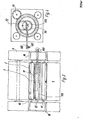
- Fig. 2 shows the embodiment of Fig. 1 in a similar form.
- the order station 1 is mounted on the machine frame 6.
- Both side bearing heads 16 can be seen, between which the rollers 10, 11 and 12 are mounted.
- the drive of the rollers 10 and 11 can also be seen, as can the drive of the doctor roller as the application device 3.
- the upper roller 12 is removed in this exemplary embodiment in order to get a final view of the application station 1.
- the cross member 15 can be seen here, on the holder 115 of which the side delimiters 14 are fastened.
- two guide cross members 52 are shown, to which the outflow devices 50 are fastened by means of displaceable holders 51, which in the exemplary embodiment shown are two cranked tubes.
- the tubular rods 150 are ge through a side bearing head 16 to the outside leads and connected here with their oscillation drive. By means of this oscillation drive, these tube rods 150 are pushed into the application station and pulled out again, the guidance being forced by the slidable holders 51, as already mentioned.
- the movement path of the flow means 50 may completely overlap, and depending on the setting of the arbitrarily be formed oscillatory 7, the respective A may be r-beitsbreite of each flow means 50 to set.
- Fig. 3 an embodiment is shown, which is shown somewhat simplified and can work with an oscillation drive according to Fig. 4 or with two such drives.
- the schematically represented side bearing heads 16, in which the rollers 10 and 11 are arranged, are again on the machine frame 6, while the upper roller 12 lies above the filling device.
- the application device 3 is designed as a slot doctor, which is designed with an open bottom to the screen 2 and can thus be box-like.
- the one on the inlet side. Wall 13 can also be formed separately, as shown in FIG. 1.
- the tubular rods 150 which are next to one another or also at an angle in relation to one another or are in relation to the application plane, are guided back and forth by one of the side bearing heads 16 in such a way that they apply the application device, which can be designed as a slot doctor blade, just fill.
- the rear wall which lies on the discharge side of the web or printing blanket or screen 2, can be designed like a squeegee and the entire box sits sealingly on the screen 2, which is known per se with slot doctor blades.
- 4 shows an oscillation drive for the tubular rods 150.
- a sun gear ring 70 is driven by a pinion 71 and has toothing on the inside and outside.
- a planet gear 72 which corresponds exactly in the pitch circle to half the diameter of the pitch circle of the internal toothing of the sun gear ring.
- a bearing pin 172 is arranged, which moves back and forth exactly on one plane when the planet gear 72 rotates, so that insertion and removal of the associated tubular rod 1 50 is made possible the foam generating device shown in FIG. 7 receives the foam to be introduced.
- an application station 1 is shown again, which works with a screen 2, which is designed as a screen belt 2.
- the belt runs here again over three rollers 10, 11 and 12.
- the side bearing heads 16 are also shown only schematically and the entire unit can be in relation to the goods to be treated, namely a web; adjust, which preferably consists of fibrous material. It is particularly intended for dyeing carpets.
- the outflow device 50 shown here has two outlets and is connected to a single pipe rod 150 which receives foam via a hose 80 from a foam generating device 8 shown in FIG. This feed device 5 is again suspended from a guide crossmember 52 via a slidable holder 51.
- the oscillation drive is shown as a rack 73, driven by a pinion 74, the motor, not shown, of which is reversed in the direction of rotation by limit switches 75, the limit switches 75in their width or their distance from each other are adjustable.
- a finger 76 strikes one of the limit switches 75 during the reciprocating movement, as a result of which the motor driving the pinion 74 is reversed.
- the applied foam is pressed in this embodiment by a roller doctor located behind the roller 11 through the screen belt onto the web 9, or the like with the interposition of a printing blanket.
- a roller doctor located behind the roller 11 through the screen belt onto the web 9, or the like with the interposition of a printing blanket.
- a doctor blade can be used and, as already mentioned, a slot doctor blade or a doctor blade box with an open bottom.
- This device can also be introduced into a circular template. Installation is somewhat more difficult, e.g. on a flat-level stencil with a reciprocating squeegee.
- FIG. 6 shows an exemplary embodiment in which the outflow device 50 is only short, but instead the hose 80 is guided into the interior of the rotating screen belt 2 or via a. flat stencil or the like
- the outflow end 50 of the hose 80 is held in a reciprocating carriage 151, which replaces the slidable holder 51 and has a small, not shown drive motor inside with a drive pinion that runs on a rack 152, which replaces the guide cross member 52.
- limit switches 175 can be arranged in the interior of the sieve 2, which cooperate with the carriage 151 and respectively reverse the small motor that drives a pinion and is present in the interior of the carriage 151.
- the movement path of each carriage 151 is limited by two limit switches 175.
- the hose 80 can be suspended from rings 81, which in turn slide on a rod 82.
- the application device 3 is a suction box 30 as a suction device.
- Fig. 7 shows the foam generating device for producing chemical-containing foam.
- the production of such a foam is previously known.
- the foam can be produced according to DE-OS 25 23 062.
- the foam is introduced into a screen cylinder 2, which is designed in a manner known per se like rotating stencils.
- the pipe rod 150 shown is stored in a side bearing head, not shown, and can be moved back and forth.
- the liquid is brought from a liquid supply 84 via a flow meter 85 into a mixing head 86, which has a mixing container 186 inside.
- the air is supplied by a compressor 87 or the like. aus.
- the air is introduced into an annular space 286 and passes through openings 386 from below into the mixing container 186, which contains granules inside. Glass balls and the like can have.
- the foam given in the hose 80 will be drier or wetter.
- liquid supply 84 there is a foaming agent, e.g. used in the production of cleaning liquids, present, mixed with, for example, water and liquid-soluble paint or another finishing liquor.
- a foaming agent e.g. used in the production of cleaning liquids, present, mixed with, for example, water and liquid-soluble paint or another finishing liquor.
- the frothing device can also be designed differently.
- the idea of the invention can be varied in many ways and can be implemented relatively easily in the process. It is essential to apply foam provided with liquor into the interior or onto the surface of a sieve 2, preferably in front of an application device 3, such as a squeegee and the like, in such quantities and in such a uniform manner that the application device is preferably relatively uniform can apply a large amount of foam through the sieve to the goods. It can be a university order, any, e.g. limited areas, e.g. when printing with screen printing stencils are printed with this foam provided with dye. The uniform and sufficient supply of foam over the total working width is important, but in particular also that this supply is possible with relatively simple means.
- suction box 30 can be arranged in addition to the application device 3 as a doctor blade, but it can also serve as an application device alone.
Applications Claiming Priority (2)
| Application Number | Priority Date | Filing Date | Title |
|---|---|---|---|
| DE19803034805 DE3034805A1 (de) | 1980-09-16 | 1980-09-16 | Vorrichtung zur zufuehrung eines auftragsmediums vor eine auftragseinrichtung im inneren einer rotierenden bzw. auf einer ebenen schablone |
| DE3034805 | 1980-09-16 |
Publications (1)
| Publication Number | Publication Date |
|---|---|
| EP0049362A1 true EP0049362A1 (fr) | 1982-04-14 |
Family
ID=6112007
Family Applications (1)
| Application Number | Title | Priority Date | Filing Date |
|---|---|---|---|
| EP81106717A Withdrawn EP0049362A1 (fr) | 1980-09-16 | 1981-08-28 | Dispositif d'alimentation pour l'apport d'un matériau de revêtement à une surface, le matériau de revêtement étant placé en face d'un dispositif d'application |
Country Status (4)
| Country | Link |
|---|---|
| EP (1) | EP0049362A1 (fr) |
| JP (1) | JPS57110361A (fr) |
| BR (1) | BR8105898A (fr) |
| DE (1) | DE3034805A1 (fr) |
Cited By (4)
| Publication number | Priority date | Publication date | Assignee | Title |
|---|---|---|---|---|
| GB2216042A (en) * | 1988-02-23 | 1989-10-04 | Mcgavigan John & Co Ltd | Spreadable material applicator |
| FR2632896A1 (fr) * | 1988-06-20 | 1989-12-22 | Perquis Vincent | Systeme d'alimentation automatique en encre pour l'impression serigraphique a plat |
| EP0358434A2 (fr) * | 1988-09-07 | 1990-03-14 | Acumeter Laboratories Inc. | Procédé et appareil de sérigraphie |
| WO2000068011A1 (fr) * | 1999-05-07 | 2000-11-16 | Stork Brabant B.V. | Appareil de dosage et de distribution d'adhesif thermo-fusible |
Families Citing this family (3)
| Publication number | Priority date | Publication date | Assignee | Title |
|---|---|---|---|---|
| JPS58122074A (ja) * | 1982-01-18 | 1983-07-20 | Sumitomo Heavy Ind Ltd | 無溶剤型ラミネ−タ用2液接着剤塗工装置 |
| US4485736A (en) * | 1983-08-26 | 1984-12-04 | Strutz Jr Carl | Ink-dispensing system and method for silk-screen printing having squeegee stroke movement counter |
| CN112428670B (zh) * | 2020-11-10 | 2021-12-31 | 陈小英 | 丝网印刷机 |
Citations (3)
| Publication number | Priority date | Publication date | Assignee | Title |
|---|---|---|---|---|
| US3257483A (en) * | 1963-11-05 | 1966-06-21 | Specialty Converters | Method of applying foam to fabrics |
| GB1071191A (en) * | 1963-12-24 | 1967-06-07 | Johnson & Johnson | Absorbent non-woven fibrous product |
| DE1435105A1 (de) * | 1959-06-15 | 1969-07-17 | Interchem Corp | Verfahren zum selektiven Aufbringen eines natuerlichen oder kuenstlichen Polymerisats auf poroese,bandfoermige,textile Traeger |
-
1980
- 1980-09-16 DE DE19803034805 patent/DE3034805A1/de not_active Withdrawn
-
1981
- 1981-08-28 EP EP81106717A patent/EP0049362A1/fr not_active Withdrawn
- 1981-09-15 BR BR8105898A patent/BR8105898A/pt unknown
- 1981-09-16 JP JP14480781A patent/JPS57110361A/ja active Pending
Patent Citations (3)
| Publication number | Priority date | Publication date | Assignee | Title |
|---|---|---|---|---|
| DE1435105A1 (de) * | 1959-06-15 | 1969-07-17 | Interchem Corp | Verfahren zum selektiven Aufbringen eines natuerlichen oder kuenstlichen Polymerisats auf poroese,bandfoermige,textile Traeger |
| US3257483A (en) * | 1963-11-05 | 1966-06-21 | Specialty Converters | Method of applying foam to fabrics |
| GB1071191A (en) * | 1963-12-24 | 1967-06-07 | Johnson & Johnson | Absorbent non-woven fibrous product |
Cited By (6)
| Publication number | Priority date | Publication date | Assignee | Title |
|---|---|---|---|---|
| GB2216042A (en) * | 1988-02-23 | 1989-10-04 | Mcgavigan John & Co Ltd | Spreadable material applicator |
| FR2632896A1 (fr) * | 1988-06-20 | 1989-12-22 | Perquis Vincent | Systeme d'alimentation automatique en encre pour l'impression serigraphique a plat |
| EP0358434A2 (fr) * | 1988-09-07 | 1990-03-14 | Acumeter Laboratories Inc. | Procédé et appareil de sérigraphie |
| EP0358434A3 (fr) * | 1988-09-07 | 1990-07-11 | Acumeter Laboratories Inc. | Procédé et appareil de sérigraphie |
| WO2000068011A1 (fr) * | 1999-05-07 | 2000-11-16 | Stork Brabant B.V. | Appareil de dosage et de distribution d'adhesif thermo-fusible |
| US6656274B2 (en) | 1999-05-07 | 2003-12-02 | Stork Brabant B.V. | Device for the dosing and distribution of hotmelt |
Also Published As
| Publication number | Publication date |
|---|---|
| JPS57110361A (en) | 1982-07-09 |
| DE3034805A1 (de) | 1982-03-25 |
| BR8105898A (pt) | 1982-06-08 |
Similar Documents
| Publication | Publication Date | Title |
|---|---|---|
| EP0047908A1 (fr) | Installation d'enduction de matériau en bande | |
| AT393246B (de) | Auftragsvorrichtung zum aufbringen fliessfaehiger medien auf ebene flaechen, bahnen, walzen od. dgl. | |
| EP0082465A1 (fr) | Appareil pour fournir un agent en mousse à un dispositif d'enduction | |
| DE2057152B2 (de) | Getufteter Teppich | |
| DE2300289A1 (de) | Vorrichtung zum auftragen fluessiger oder pastoeser medien, insbesondere fuer siebdruckmaschinen | |
| DE3020668A1 (de) | Verfahren und vorrichtung zum behandeln einer vorlaufenden warenbahn | |
| DE3044409A1 (de) | Vorrichtung zum auftragen verschaeumter flotte | |
| EP0047907B1 (fr) | Installation d'enduction de matériaux en bandes | |
| EP0047887A1 (fr) | Dispositif d'application d'un matériau (bain d'ennoblissement) à une surface au moyen d'un dispositif d'application | |
| DE3151511A1 (de) | Vorrichtung zum gleichmaessigen verteilen von fluessigen, viskosen oder verschaeumten flotten | |
| EP0049362A1 (fr) | Dispositif d'alimentation pour l'apport d'un matériau de revêtement à une surface, le matériau de revêtement étant placé en face d'un dispositif d'application | |
| DE3128324A1 (de) | Rotierend angetriebene zylinderschablone zum faerben und drucken von flaechigen waren bzw. warenbahnen | |
| EP0098362A1 (fr) | Fente d'amenée de matériaux en mousse sur des matières en bandes | |
| DE3137763A1 (de) | "siebzylinder zur aufbringung von fluessigkeiten enthaltenden auftragsmassen auf flaechige waren, z.b. warenbahnen od.dgl." | |
| DE3034802A1 (de) | Verfahren und vorrichtung zum gleichmaessigen auftragen von fluessigen behandlungsflotten auf textile flaechengebilde | |
| DE3200171C2 (de) | Vorrichtung zum Auftragen eines vorzugsweise mit Farbstoff versehenen Auftragsmediums auf eine flächige Ware | |
| DE3034803C2 (de) | Anwendung des Siebdruckverfahrens bzw. einer Siebdruckvorrichtung | |
| DE3127469A1 (de) | Vorrichtung zum auftragen von fluessigen, verschaeumten oder pastoesen medien auf eine warenbahn | |
| EP0048348A1 (fr) | Procédé et installation d'enduction uniforme de matériaux en bandes par des liquides, des bains ou des pâtes | |
| DE3150936A1 (de) | Vorrichtung zum zufuehren von schaum zu einem abnehmer, z.b. einer auftragsstation | |
| DE3524127A1 (de) | Auftragsvorrichtung bzw. schlitzrakel zum kontinuierlichen auftragen eines verschaeumten, pastoesen oder trockenen auftragsmediums | |
| DE2900658C2 (de) | Vorrichtung zum Aufbringen von insbeosndere Farbe auf eine Warenbahn, vorzugsweise eine textile Warenbahn | |
| EP0100883B1 (fr) | Installation d'apport et d'enduction de mousse sur une matière en bande | |
| DE2363506C3 (de) | Vorrichtung zur Behandlung von fadenförmigem Textilgut | |
| EP0108274A1 (fr) | Installation permettant d'apporter une mousse et d'en enduire une bande textile |
Legal Events
| Date | Code | Title | Description |
|---|---|---|---|
| PUAI | Public reference made under article 153(3) epc to a published international application that has entered the european phase |
Free format text: ORIGINAL CODE: 0009012 |
|
| AK | Designated contracting states |
Designated state(s): AT CH DE FR GB IT NL |
|
| 17P | Request for examination filed |
Effective date: 19820729 |
|
| STAA | Information on the status of an ep patent application or granted ep patent |
Free format text: STATUS: THE APPLICATION HAS BEEN WITHDRAWN |
|
| 18W | Application withdrawn |
Withdrawal date: 19840323 |