EP0048935A2 - Schaltungsanordnung zum phasenrichtigen Starten eines quarzgesteuerten Taktoszillators - Google Patents
Schaltungsanordnung zum phasenrichtigen Starten eines quarzgesteuerten Taktoszillators Download PDFInfo
- Publication number
- EP0048935A2 EP0048935A2 EP81107530A EP81107530A EP0048935A2 EP 0048935 A2 EP0048935 A2 EP 0048935A2 EP 81107530 A EP81107530 A EP 81107530A EP 81107530 A EP81107530 A EP 81107530A EP 0048935 A2 EP0048935 A2 EP 0048935A2
- Authority
- EP
- European Patent Office
- Prior art keywords
- frequency
- quartz
- circuit
- oscillator
- trigger pulse
- Prior art date
- Legal status (The legal status is an assumption and is not a legal conclusion. Google has not performed a legal analysis and makes no representation as to the accuracy of the status listed.)
- Granted
Links
- 239000010453 quartz Substances 0.000 title claims abstract description 9
- VYPSYNLAJGMNEJ-UHFFFAOYSA-N silicon dioxide Inorganic materials O=[Si]=O VYPSYNLAJGMNEJ-UHFFFAOYSA-N 0.000 title claims abstract description 9
- 230000010355 oscillation Effects 0.000 claims abstract description 5
- 238000000034 method Methods 0.000 claims abstract description 4
- 230000008569 process Effects 0.000 claims abstract description 4
- 230000001360 synchronised effect Effects 0.000 claims abstract description 4
- 230000001960 triggered effect Effects 0.000 claims abstract 2
- 230000005540 biological transmission Effects 0.000 abstract description 9
- 238000010586 diagram Methods 0.000 description 3
- 230000006872 improvement Effects 0.000 description 2
- 238000005070 sampling Methods 0.000 description 2
- 230000001629 suppression Effects 0.000 description 2
- 230000004913 activation Effects 0.000 description 1
- 230000001427 coherent effect Effects 0.000 description 1
- 230000008878 coupling Effects 0.000 description 1
- 238000010168 coupling process Methods 0.000 description 1
- 238000005859 coupling reaction Methods 0.000 description 1
- 239000013078 crystal Substances 0.000 description 1
- 230000004044 response Effects 0.000 description 1
- 230000000630 rising effect Effects 0.000 description 1
Images

Classifications
-
- H—ELECTRICITY
- H03—ELECTRONIC CIRCUITRY
- H03L—AUTOMATIC CONTROL, STARTING, SYNCHRONISATION OR STABILISATION OF GENERATORS OF ELECTRONIC OSCILLATIONS OR PULSES
- H03L7/00—Automatic control of frequency or phase; Synchronisation
- H03L7/06—Automatic control of frequency or phase; Synchronisation using a reference signal applied to a frequency- or phase-locked loop
- H03L7/08—Details of the phase-locked loop
- H03L7/099—Details of the phase-locked loop concerning mainly the controlled oscillator of the loop
- H03L7/0991—Details of the phase-locked loop concerning mainly the controlled oscillator of the loop the oscillator being a digital oscillator, e.g. composed of a fixed oscillator followed by a variable frequency divider
- H03L7/0992—Details of the phase-locked loop concerning mainly the controlled oscillator of the loop the oscillator being a digital oscillator, e.g. composed of a fixed oscillator followed by a variable frequency divider comprising a counter or a frequency divider
Definitions
- the invention relates to a circuit arrangement for starting a crystal-controlled clock oscillator with the correct phase, with variable pulse repetition frequency (PRF) in radar devices in the case of transmit pulses.
- PRF variable pulse repetition frequency
- the distance gate clock (sampling clock of the received signal) is severely jittered with respect to the envelope of the transmission pulse when the clock oscillator runs through.
- a trigger pulse is derived from the rising flake of the transmission pulse, with which the clock oscillator must be synchronized in a phase-locked manner. Since the phase reference (trigger pulse) consists of only one pulse, a phase-locked synchronization of the clock oscillator via phase locked loops is not possible.
- the invention has for its object to provide a circuit for a circuit arrangement of the type mentioned that enables the high-frequency oscillator to be started in phase by a trigger pulse.
- this object is achieved in that a quartz-controlled oscillator oscillation in a frequency multiplier stage is raised to an integer multiple of the range gate clock frequency, divided down to the transmission frequency in a subsequent resettable frequency divider circuit, and the division process is synchronized with the trigger pulse.
- the quartz-stable signal f (distance gate clock frequency) should be able to be started in phase by a trigger pulse TP. No periodicity of the trigger pulses may be assumed (t TP1 ⁇ t TP2 ).
- the quartz-stable oscillation fs must be coherent between the trigger pulse between two trigger pulses. In the ideal case of the phase-locked coupling between trigger pulse TP and vibration fs, the time t x between the start command and the zero crossing of the signal is constant.
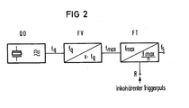
- an exemplary embodiment for carrying out a low-jitter connection of trigger pulse and vibration contains a quartz oscillator Q0, a frequency multiplier FV and a frequency divider FT with a reset option.
- the triggerable signal f s (transmission frequency) is derived from a multiple of the quartz-controlled oscillation f q .
- the quartz oscillator QO of known design generates the signal of frequency f q , which is multiplied to the value xf max in the frequency multiplier FV.
- the frequency f max is finally divided down to the desired transmission frequency f.
- the frequency divider FT can be set via a special input R. or resettable. Such frequency dividers are known. If a trigger pulse TP is present at the reset input R, with the first zero crossing of the frequency f max, the frequency division in the first of several stages of the frequency divider (flip-flop) represents activation points of the first frequency divider. The transmission frequency f s is then phase-locked except for a small residual jitter coupled to the trigger.
- the low jitter values achievable with the circuit according to the invention lead to an improvement in the fixed character suppression and to a substantial improvement in the distance determination in a radar receiver.
Landscapes
- Stabilization Of Oscillater, Synchronisation, Frequency Synthesizers (AREA)
- Manipulation Of Pulses (AREA)
Abstract
Description
- Die Erfindung bezieht sich auf eine Schaltungsanordnung zum phasenrichtigen Starten eines quarzgesteuerten Taktoszillators, bei Sendeimpulsen veränderbarer Pulsfolgefrequenz (PRF) in Radargeräten.
- In Radarsendern mit sich laufend ändernder Impulsfolgefrequenz (PFR) und mit gepulsten, selbstschwingenden Senderendstufen ist der Entfernungstortakt (Abtast-Takt des empfangenen Signals) in Bezug auf die Einhüllende des Sendeimpulses bei durchlaufendem Taktoszillator stark verjittert.
- Dadurch wird notwendig, den Entfernungstortakt auf die Flanken des Sendeimpulses jedesmal neu auszurichten, da die Festzeichenunterdrückung im Radarempfänger von der exakten Abtastung der empfangenen Echosignale abhängt.
- Hierzu wird von der Anstiegsflaake des Sendeimpulses ein Triggerimpuls hergeleitet, mit dem der Taktoszillator phasenstarr synchronisiert werden muß. Da die Phasenreferenz (Triggerimpuls) nur aus einem einzigen Puls besteht, ist eine phasenstarre Synchronisation des Taktoszillators über Phase Locked Loops nicht möglich.
- Bisher hat man sich mit Taktoszillatoren mit geringen Resonatorgüten beholfen, die mit jedem Triggerimpuls neu gestartet und nach dem Ende der Empfängerperiode gestoppt wurden. Durch die geringen Resonatorgüten war es möglich, den Oszillator einigermaßen phasenrichtig zu starten. Der Ausgang eines NAND-Gatters wurde über eine Verzögerungsleitung (Resonator) auf einen Gattereingang zurückgekoppelt. Mit dem zweiten Gattereingang wurde die Schaltung aktiviert (Start) bzw. außer Betrieb gesetzt (Stop).
- Hohe Ungenauigkeit der Taktfrequenz und großer Temperaturgang, bedingt durch die Eigenschaften der Verzögerungsleitung, waren die Folge.
- Der Erfindung liegt die Aufgabe zugrunde, für eine Schaltungsanordnung der eingangs genannten Art eine Schaltung anzugeben, die es ermöglicht, den Hochfrequenzoszillator durch einen Triggerpuls phasenrichtig zu starten.
- Gemäß der Erfindung wird diese Aufgabe dadurch gelöst, daß eine quarzgesteuerte Oszillatorschwingung in einer Frequenzvervielfacher-Stufe auf ein ganzzahliges Vielfaches der Entfernungstortaktfrequenz angehoben, in einer nachfolgenden rücksetzbaren Frequenzteilerschaltung auf die Sendefrequenz heruntergeteilt und der Teilungsvorgang auf den Triggerpuls synchronisiert wird.
- Durch diese Schaltungsmaßnahmen.ist das Ausgangssignal (Entfernungstortakt) bis auf einen kleinen Restjitter phasenstarr an den Triggerimpuls gekoppelt. Der Restjitter (tj) wird um so kleiner, je höher die Frequenz (fmax) am Ausgang der Vervielfacher-Stufe gewählt ist. Die obere Grenze von (fmax) ist durch die maximale Clock-Frequenz der verfügbaren Teilerbausteine gegeben.
- Die Erfindung und weitere Einzelheiten der Erfindung werden anhand der Fig. 2 bis 3 näher erläutert.
- Es zeigen
- Fig. 1 ein Impulsdiagramm mit Triggerpulsfolge und Sendefrequenz
- Fig. 2 ein Blockschaltbild der Schaltungsanordnung zum phasenrichtigen Triggern
- Fig. 3 ein Impulsdiagramm zur Erläuterung der Wirkungsweise dieser Schaltungsanordnung.
- Anhand der beiden Impulszüge in Fig. 1 wird verdeutlicht, welche Anforderung an einen jitterarmen Start-Stop-Oszillator gestellt wird. Das quarzstabile Signal f (Entfernungstortaktfrequenz) soll von einem Triggerpuls TP phasenrichtig gestartet werden können. Dabei darf keine Periodizität der Triggerpulse vorausgesetzt werden (tTP1≠tTP2). Die quarzstabile Schwingung fs muß zwischen zwei Triggerpulsen kohärent zum auslösenden Triggerpuls sein. Im Idealfall der phasenstarren Kopplpng zwischen Triggerpuls TP und Schwingung fs ist die Zeit tx zwischen Startbefehl und Nulldurchgang des Signals konstant.
- Ein Ausführungsbeispiel für die Durchführung einer jitterarmen Anbindung von Triggerpuls und Schwingung enthält nach Fig. 2 einen Quarzoszillator Q0, einen Frequenzvervielfacher FV und einen Frequenzteiler FT mit Rücksetzmöglichkeit. Um die angestrebte hohe Frequenzstabilität zu erreichen, wird das triggerbare Signal fs (Sendefrequenz) aus einem Vielfachen der quarzkontrollierten Schwingung fq abgeleitet. Der Quarzoszillator QO bekannter Ausführung erzeugt das Signal der Frequenz fq, das im Frequenzvervielfacher FV auf den Wert x.fmax vervielfacht wird.
- Im Frequenzteiler FT wird schließlich die Frequenz fmax auf die gewünschte Sendefrequenz f.heruntergeteilt. Für den Synchronisiervorgang ist vorausgesetzt, daß der Frequenzteiler FT über einen besonderen Eingang R setzbar oder rücksetzbar ist. Derartige Frequenzteiler sind bekannt. Bei Anliegen eines Triggerpulses TP am Rücksetzeingang R setzt mit dem ersten Nulldurchgang der Frequenz fmax die Frequenzteilung in der ersten von mehreren Stufen des Frequenzteilers (Flip-Flop) Aktivierungspunkte des ersten Frequenzteilers dar. Die Sendefrequenz fs ist dann bis auf einen kleinen Restjitter phasenstarr an den Trigger gekoppelt.
- Wenn in einem Radarsystem ein maximaler Jitter von z.B. 2ns zwischen Triggerpuls TP und Sendefrequenz fs zugelassen werden darf, ergibt sich folgendes Zahlenbeispiel:
-


- Die mit der Schaltung gemäß der Erfindung erzielbaren geringen Jitterwerte führen zur einer Verbesserung der Festzeichenunterdrückung, sowie zu einer wesentlichen Verbesserung der Entfernungsbestimmung in einem Radarempfänger.
Claims (2)
Applications Claiming Priority (2)
| Application Number | Priority Date | Filing Date | Title |
|---|---|---|---|
| DE19803036712 DE3036712C2 (de) | 1980-09-29 | 1980-09-29 | Schaltungsanordnung zum phasenrichtigen Triggern eines quarzgesteuerten Taktoszillators |
| DE3036712 | 1980-09-29 |
Publications (4)
| Publication Number | Publication Date |
|---|---|
| EP0048935A2 true EP0048935A2 (de) | 1982-04-07 |
| EP0048935A3 EP0048935A3 (en) | 1982-09-15 |
| EP0048935B1 EP0048935B1 (de) | 1984-09-26 |
| EP0048935B2 EP0048935B2 (de) | 1990-02-28 |
Family
ID=6113142
Family Applications (1)
| Application Number | Title | Priority Date | Filing Date |
|---|---|---|---|
| EP19810107530 Expired - Lifetime EP0048935B2 (de) | 1980-09-29 | 1981-09-22 | Schaltungsanordnung zum phasenrichtigen Starten eines quarzgesteuerten Taktoszillators |
Country Status (2)
| Country | Link |
|---|---|
| EP (1) | EP0048935B2 (de) |
| DE (1) | DE3036712C2 (de) |
Cited By (2)
| Publication number | Priority date | Publication date | Assignee | Title |
|---|---|---|---|---|
| WO1989004974A1 (en) * | 1987-11-23 | 1989-06-01 | Allied-Signal Inc. | Crystal controlled magnetron |
| US20110133797A1 (en) * | 2005-12-29 | 2011-06-09 | Orca Systems, Inc. | Novel method of frequency synthesis for fast switching |
Family Cites Families (6)
| Publication number | Priority date | Publication date | Assignee | Title |
|---|---|---|---|---|
| DE2217967C2 (de) * | 1972-04-14 | 1984-03-08 | ANT Nachrichtentechnik GmbH, 7150 Backnang | Schaltungsanordnung zur Frequenznachregelung eines freischwingenden Oszillators |
| FR2218695B1 (de) * | 1973-02-21 | 1977-04-22 | Materiel Telephonique | |
| NL171931C (nl) * | 1973-09-21 | 1983-06-01 | Hollandse Signaalapparaten Bv | Impulsradarapparaat. |
| DE2729436C3 (de) * | 1977-06-29 | 1980-10-09 | Siemens Ag, 1000 Berlin Und 8000 Muenchen | Pulsradargerät mit im Totbereich abweichend getakteten Schieberegistern im Signalauswerteteil |
| DE2812158A1 (de) * | 1978-03-20 | 1979-09-27 | Licentia Gmbh | Oszillator nach dem pll-prinzip |
| DE2911450A1 (de) * | 1979-03-23 | 1980-09-25 | Ludger Mersmann | Vorrichtung zur erzeugung elektromagnetischer oder mechanischer schwingungen mit digitaler oder analoger messung der ausgangsfrequenz oder der periodendauer |
-
1980
- 1980-09-29 DE DE19803036712 patent/DE3036712C2/de not_active Expired
-
1981
- 1981-09-22 EP EP19810107530 patent/EP0048935B2/de not_active Expired - Lifetime
Cited By (2)
| Publication number | Priority date | Publication date | Assignee | Title |
|---|---|---|---|---|
| WO1989004974A1 (en) * | 1987-11-23 | 1989-06-01 | Allied-Signal Inc. | Crystal controlled magnetron |
| US20110133797A1 (en) * | 2005-12-29 | 2011-06-09 | Orca Systems, Inc. | Novel method of frequency synthesis for fast switching |
Also Published As
| Publication number | Publication date |
|---|---|
| EP0048935B1 (de) | 1984-09-26 |
| DE3036712C2 (de) | 1982-11-25 |
| DE3036712A1 (de) | 1982-04-08 |
| EP0048935B2 (de) | 1990-02-28 |
| EP0048935A3 (en) | 1982-09-15 |
Similar Documents
| Publication | Publication Date | Title |
|---|---|---|
| DE69027493T2 (de) | Digitaler Zeitbasisgenerator mit einstellbarer Verzögerung zwischen zwei Ausgängen | |
| DE69405791T2 (de) | Rauscharmer Breitband-PLL-Frequenzsynthetisierer mit feinen Frequenzstufen | |
| DE10393009B4 (de) | Stabilisierung von Oszillatoren für einen leistungsarmen Radar-Füllstandtransmitter | |
| DE1135533B (de) | Schaltung zur gemeinsamen Erzeugung von Mikrowellen-Sendeschwingungen und Mikrowellen-Empfangsueberlagerer-schwingungen fuer Radargeraete mit Ausnuetzung des Dopplereffektes | |
| DE2847348A1 (de) | Hoehensimulator fuer radarhoehenmesser | |
| DE102009027495B4 (de) | Heterodyn-Sende-/Empfangssysteme und Verfahren | |
| EP2199762B1 (de) | Sensor und Verfahren zur Messung der Entfernung einer Grenzfläche | |
| DE3587002T2 (de) | Signalgeneratorschaltungen. | |
| EP0048935B1 (de) | Schaltungsanordnung zum phasenrichtigen Starten eines quarzgesteuerten Taktoszillators | |
| DE2613930C3 (de) | Digitaler Phasenregelkreis | |
| DE4216148C2 (de) | Verriegelungsschaltung für einen dualen Phasenregelkreis | |
| DE2735053A1 (de) | Digitaler phasenregelkreis | |
| DE69118114T2 (de) | Frequenzteiler-Netwerk mit niedrigen Phasenrauschen | |
| DE3101974C1 (de) | Impulsradar | |
| EP0202597B1 (de) | Schaltungsanordnung zur Rückgewinnung des Taktes eines isochronen Binärsignales | |
| DE69026144T2 (de) | Verfahren und Vorrichtung zur Einstellung der Frequenz für ein Funksendegerät | |
| DE978064C (de) | Impuls-Doppler-Radargerät | |
| DE1943185A1 (de) | Verfahren zur Datenuebertragung | |
| DE2729436A1 (de) | Pulsradargeraet mit im signalauswerteteil angeordneten, getakteten speichereinrichtungen | |
| DE2838254C2 (de) | ||
| DE977823C (de) | Sendegenerator treppenfoermig frequenzmodulierter Impulse | |
| DE1962156C (de) | Rundfunkempfänger fur Einseitenband Empfang | |
| DE1934225C3 (de) | Verfahren zum Frequenzumtasten durch Binärzeichen | |
| DE1591722C3 (de) | Frequenzaufbereitung nach dem Prinzip des digitalen Zählverfahrens | |
| DE2834230C2 (de) | Verfahren zur selbsttätigen Gleichlaufeinstellung zwischen Vor- und Oszillatorkreis in einem Überlagerungsempfänger und Schaltungsanordnung zur Durchführung dieses Verfahrens |
Legal Events
| Date | Code | Title | Description |
|---|---|---|---|
| PUAI | Public reference made under article 153(3) epc to a published international application that has entered the european phase |
Free format text: ORIGINAL CODE: 0009012 |
|
| 17P | Request for examination filed |
Effective date: 19811030 |
|
| AK | Designated contracting states |
Designated state(s): BE CH FR GB IT NL |
|
| PUAL | Search report despatched |
Free format text: ORIGINAL CODE: 0009013 |
|
| AK | Designated contracting states |
Designated state(s): BE CH FR GB IT NL |
|
| ITF | It: translation for a ep patent filed | ||
| GRAA | (expected) grant |
Free format text: ORIGINAL CODE: 0009210 |
|
| AK | Designated contracting states |
Designated state(s): BE CH FR GB IT LI NL |
|
| ET | Fr: translation filed | ||
| PLBI | Opposition filed |
Free format text: ORIGINAL CODE: 0009260 |
|
| 26 | Opposition filed |
Opponent name: WANDEL & GOLTERMANN GMBH & CO Effective date: 19850613 |
|
| NLR1 | Nl: opposition has been filed with the epo |
Opponent name: WANDEL & GOLTERMANN GMBH & CO |
|
| PUAH | Patent maintained in amended form |
Free format text: ORIGINAL CODE: 0009272 |
|
| STAA | Information on the status of an ep patent application or granted ep patent |
Free format text: STATUS: PATENT MAINTAINED AS AMENDED |
|
| 27A | Patent maintained in amended form |
Effective date: 19900228 |
|
| AK | Designated contracting states |
Kind code of ref document: B2 Designated state(s): BE CH FR GB IT NL |
|
| ET3 | Fr: translation filed ** decision concerning opposition | ||
| NLR2 | Nl: decision of opposition | ||
| ITF | It: translation for a ep patent filed | ||
| NLR3 | Nl: receipt of modified translations in the netherlands language after an opposition procedure | ||
| PGFP | Annual fee paid to national office [announced via postgrant information from national office to epo] |
Ref country code: GB Payment date: 19900816 Year of fee payment: 10 |
|
| PGFP | Annual fee paid to national office [announced via postgrant information from national office to epo] |
Ref country code: BE Payment date: 19900913 Year of fee payment: 10 |
|
| PGFP | Annual fee paid to national office [announced via postgrant information from national office to epo] |
Ref country code: FR Payment date: 19900925 Year of fee payment: 10 |
|
| ITTA | It: last paid annual fee | ||
| PGFP | Annual fee paid to national office [announced via postgrant information from national office to epo] |
Ref country code: NL Payment date: 19900930 Year of fee payment: 10 |
|
| PGFP | Annual fee paid to national office [announced via postgrant information from national office to epo] |
Ref country code: CH Payment date: 19901217 Year of fee payment: 10 |
|
| PG25 | Lapsed in a contracting state [announced via postgrant information from national office to epo] |
Ref country code: GB Effective date: 19910922 |
|
| PG25 | Lapsed in a contracting state [announced via postgrant information from national office to epo] |
Ref country code: CH Effective date: 19910930 Ref country code: LI Effective date: 19910930 Ref country code: BE Effective date: 19910930 |
|
| BERE | Be: lapsed |
Owner name: SIEMENS A.G. BERLIN UND MUNCHEN Effective date: 19910930 |
|
| PG25 | Lapsed in a contracting state [announced via postgrant information from national office to epo] |
Ref country code: NL Effective date: 19920401 |
|
| NLV4 | Nl: lapsed or anulled due to non-payment of the annual fee | ||
| GBPC | Gb: european patent ceased through non-payment of renewal fee | ||
| PG25 | Lapsed in a contracting state [announced via postgrant information from national office to epo] |
Ref country code: FR Effective date: 19920529 |
|
| REG | Reference to a national code |
Ref country code: CH Ref legal event code: PL |
|
| REG | Reference to a national code |
Ref country code: FR Ref legal event code: ST |
|
| APAH | Appeal reference modified |
Free format text: ORIGINAL CODE: EPIDOSCREFNO |