EP0046553A1 - Dispositif pour le soutènement de tranchées à l'aide de panneaux - Google Patents
Dispositif pour le soutènement de tranchées à l'aide de panneaux Download PDFInfo
- Publication number
- EP0046553A1 EP0046553A1 EP81106351A EP81106351A EP0046553A1 EP 0046553 A1 EP0046553 A1 EP 0046553A1 EP 81106351 A EP81106351 A EP 81106351A EP 81106351 A EP81106351 A EP 81106351A EP 0046553 A1 EP0046553 A1 EP 0046553A1
- Authority
- EP
- European Patent Office
- Prior art keywords
- rollers
- shoring
- guide
- supports
- plates
- Prior art date
- Legal status (The legal status is an assumption and is not a legal conclusion. Google has not performed a legal analysis and makes no representation as to the accuracy of the status listed.)
- Granted
Links
Images


Classifications
-
- E—FIXED CONSTRUCTIONS
- E02—HYDRAULIC ENGINEERING; FOUNDATIONS; SOIL SHIFTING
- E02D—FOUNDATIONS; EXCAVATIONS; EMBANKMENTS; UNDERGROUND OR UNDERWATER STRUCTURES
- E02D17/00—Excavations; Bordering of excavations; Making embankments
- E02D17/06—Foundation trenches ditches or narrow shafts
- E02D17/08—Bordering or stiffening the sides of ditches trenches or narrow shafts for foundations
Definitions
- the invention relates to a device for supporting the walls of a trench with large shoring plates, the side edges of which are guided and supported in guide slots located on both sides of supports, the supports being arranged in pairs opposite one another and kept at a distance by means of cross struts and to reduce the frictional resistance between the shoring panels and the supports are arranged around rollers rotating around horizontal axes.
- the shoring plates have guide heads on their lateral edges, which are guided in a vertically displaceable manner in the supports. Rollers are arranged on the guide heads, some of which are mounted on axes perpendicular to the shoring wall plane and others on axes which are in a plane between the side surfaces of the shoring plate and perpendicular to the support (DE-AS 23 23 321).
- the arrangement of rollers on the guide heads of the shoring panels has the disadvantage that this penetrated soil into the interior of the support roll on the flanges of the hollow profile and thereby impair the function of the guides.
- the object of the invention is to provide the arrangement of rollers between shoring panels and their guides in a trench shoring device in such a way that the rollers fully perform their function even under the most unfavorable conditions in civil engineering, even if they are weeks without maintenance - and left in contact with the ground and / or corrosive mine water for months without being operated.
- the arrangement is also intended to prevent damage in transit.
- Another object of the invention is to make this roller arrangement as robust and uncomplicated as possible.
- rollers on the supports are formed by a row of rollers mounted on the supports from the trench wall side of the guide slots.
- This arrangement has the advantage that, in contrast to the fastening of the rollers to the shoring panels, damage to the rollers by transport is largely prevented because these rollers, which are attached to the supports, are protected within the profiles of the supports. Robust storage of the rollers is also possible because the wall thickness of the support is considerably thicker. Damage to the rollers when inserting the sheeting plates into the guides is also not possible because they only protrude from the levels of the entries with a relatively small protrusion.
- rollers can be arranged between them in such a way that the rollers protrude between 5 and 30 mm, preferably between 10 and 20 mm, over the webs. Since the top roller is endangered when a shoring plate is inserted into the guide slots of adjacent supports, a guide bar is arranged above it to protect it. This guide web forms, together with the support wall, which forms the side of the guide slot closer to the trench wall, the upper junction.
- This opening can be widened like a funnel for easier insertion of the shoring panels into the guide slots.
- the rollers mounted on the supports can have wheel flanges which engage with vertical guide heads arranged at right angles to the plane of the shoring plates on the lateral edges of the shoring plates. This eliminates the need to arrange rollers on the axes perpendicular to the shoring wall level for the purpose of frictional connection, as is the case with the device according to DE-AS 23 23 321.
- An embodiment of the invention provides that the rollers as rolling elements in a vertical roller guide between a raceway, the roller guide and the shoring plate can be rolled vertically to a limited extent. This results in the significant advantage in construction site operation in civil engineering that this storage is largely insensitive to dirt, corrosion and wear, and it provides an expedient embodiment that the roller acting as a roller has stub axles that roll on raceways of the roller guide.
- Another embodiment of the invention provides that in order to maintain defined axial distances between adjacent supports, this longitudinal direction of the trench is connected to one another by tie rods or pull cables.
- This configuration has the advantage that a frictional connection between supports and shoring panels in the longitudinal direction is not produced by the meshing of guide heads of the shoring panels and guide profiles of the supports, but by the tension elements. This results in a design of the shoring panels and supports. Furthermore, the risk is reduced that when inserting or pulling out a shoring plate, it jams in the supports.
- the support has an outer base wall and two right-angled side walls in which at least two parallel rows of supporting rollers are arranged in order to form outer and inner guide slots which are offset parallel to the inside.
- the outer guide slots are formed by the projecting parts of the base wall and the first row of support rollers.
- the inner guide slots can be formed by the second row of support rollers and a parallel row of guide rollers spaced therefrom. The function of these guide rollers, on which the outer sides of the shoring plates come into contact and therefore do not have to absorb any major loads, can also be taken over by the supporting roles of the outer guide slot.
- guide elements such as bolts, flanges or the like, attached to the side walls of the support can also take over the function of the guide roller. Since the supporting roles and the guide roles can be completely identical and the guide roles and the supporting roles can be easily exchangeably attached to the support, it is expedient to form the inner guide slot exclusively from leading and supporting roles.
- rollers may also be expedient to arrange these rollers to form the inner guide slots only in the area of the lower half of the supports. This has the advantage that to insert the sheeting into the inner guide slots, the sheeting does not have to be lifted up over the supports.
- approximately 1 to 2 cm thick strips are arranged on the inside of the base wall in the vicinity of the edges, which cooperate with correspondingly thick strips which are welded to the outside in the edge region of the shoring panels. Since these strips are thicker than the greatest possible play of the shoring plates in the guide slots, a positive connection of the supports standing on a trench wall is achieved via the shoring plates inserted into the outer guide slots.
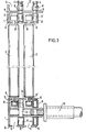
- the shoring device according to FIGS. 1 to 3 has supports 1 in whose guide slots 5 shoring plates 2 and 3 made of steel are slidably guided.
- the connection between the supports 1 and the shoring plates 2, 3 in the longitudinal direction of the trench is effected by vertical webs 4 and strips 6 connected to them.
- the webs 4, as shown in FIG. 2 are arranged at vertical distances 7 from one another. These distances form recesses in which rollers 8 are rotatably mounted on axle bolts.
- mutually opposing supports 1 are mutually supported in pairs against the pressure of the soil by means of cross struts 10, in particular spreading.
- the upper shoring plates 2 are located in the guide slots 5 closer to the trench wall and the lower shoring plates 3 are guided in the guide slots 5 closer to the center of the trench.
- rollers 11 are equipped with wheel flanges 12, which are in engagement with the guide heads 13 of the shoring plates 2 and 3 and take over the function of the strips 6 in FIGS. 1 to 3. Since rollers 11 equipped with wheel flanges 12 are loaded not only in the radial direction but also in the axial direction, they must be mounted accordingly.
- Fig. 7 shows a corresponding storage. Two opposing shoulder ball bearings 14 are provided. The bearing is sealed against ingress of dirt via O-ring seals 15.
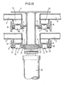
- FIGS. 8 to 10 Another embodiment of the invention is shown in FIGS. 8 to 10.
- rollers 16 designed as rolling elements are arranged between the guide head 13 of the shoring plate 2 and the web 4 of the support.
- the rollers 16 are arranged with an overhang 18 such that the final pressure absorbed by the shoring panels 2 according to the arrows 19 and 20 via the rollers 16 and their Axle stub 21 is transmitted to raceways of a vertical roller guide 17 connected to the web 4.
- the upper roller 16 is shown in its upper rolling position of its track 22, while the two lower rollers 16 are shown in their lower rolling position.
- the axle stubs 21 roll on the raceway 22 between these rolling positions.
- the axle stub 21 makes a rolling movement of 360 ° and also the periphery of the roller 16.
- the distance traveled between the installation panel 2 and the support 1 corresponds in each direction to an amount of the axle stub circumference plus the roller circumference.
- the stub axles 21 run against stoppers 23, which receive the stub axles 21 in the manner of half-shells.
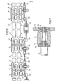
- Fig. 10 shows a support 1 with two parallel guide slots on each side of the support, so that two outer mounting plates 2 and two inner mounting plates 3 are supported in the support 1 via rollers 16 acting as rolling elements.
- the supports 1, 1 ', 1 are made of double-T profiles and are connected to one another in the longitudinal direction by tie rods 30 or pull cables 31.
- the pull rods 30 have a turnbuckle 32.
- the pull cables 31 are also included With the help of shackles 33 anchored with the supports 1 in receiving bores 34. Since the supports 1, 1 ′, 1 ′′ are kept at a defined distance via pull rods 30 and pull cables 31, the shoring plates 2, 3; 2 ', 3'; 2 ", 3" no angular guide heads.
- the steel shoring plates 2,3; 2 ', 3'; 2 ", 3” consist of welded U or Z-shaped sheet metal profiles with a wall thickness of 2 to 3 mm.
- the side edges of the shoring plate 2, 3 which are supported against the rollers 8, 8 ', 8 "of the supports 1, 1', 1" are expediently provided; 2 ', 3'; 2 ", 3” made of steel profiles with a wall thickness of at least 5 mm, or steel rails are attached to the side edges, which run on the rollers.
- the support 1 consists of a base wall 35 and two side walls 36, 37 extending at a distance from one another at right angles to the base wall 35, the edges of which are directed toward the inside of the trench and have a thickening 38, each of which is slightly bent outwards , so that the space between the two side walls 36, 37 remains free for connecting the cross struts 10 or spreading.
- the support 1 has two parallel guide slots 5 on each side.
- the outer guide slots 5, which receive the upper shoring plates 2 are formed by the base wall 35 and the rollers 8, which are fastened to the support 1 at intervals of 50 or 80 cm from one another. So that the supports 1 on a trench wall are positively connected in the longitudinal direction of the trench via the shoring plate 2, strips 41 are welded to the edges of the base wall 35, which can be 10 mm high and 20 mm wide, for example, and on the outer sides of the guide edges 43 Corresponding strips 42 are welded onto the mounting plate 2.
- the play of the guide edges 43 of the shoring plates 2, 3 between the base wall 35 of the support 1 and the supporting rollers 8 is approximately 5 mm, so that an easy insertion of the shoring plate 2 into the outer guide slot 5 is possible.
- This insertion is additionally facilitated in that a web 4 with an insertion slope 44 is arranged above the uppermost roller 8, so that the guide slots 5 are widened like a funnel at the upper end of the support 1.
- the inner guide slots 5 ' are formed by a second row of supporting rollers 8 and a row of leading rollers 28.
- the shoring plates 3 guided in the inner guide slots 5 ′ are designed in exactly the same way as the shoring plate 2 guided in the outer guide slots 5. Their strips 42 lie against the guide rollers 28 when they are inserted into the inner guide slots 5. The earth pressure is taken up by the supporting rollers 8.
- the guide rollers 28 and their axle bolts are constructed in exactly the same way as the supporting rollers 8 and their axle bolts 9 and are also fastened to the support 1 in an easily replaceable manner.
- the row of guide rollers 28 is offset somewhat inward from the row of supporting rollers 8 of the outer guide slot 5, so that the distance between the upper, outer shoring plates 2 and the lower, inner ones Shoring plates 3 is so large that deflections of the upper, outer shoring plates 2 occurring as a result of earth pressure do not lead to faults.
- the thickness of the shoring plates 2, 3 and their guide edges 43 and the diameter of the rollers 8 can also be chosen so that the function of the guide rollers 28 is taken over by the supporting rollers 8 of the outer guide slot 8.
- the upper end of the support 1 is covered by a welded-on cover 45.
- This cover 45 and the welded-in tubes 39 stiffen the support 1.
- additional transverse walls can be attached, which connect the two side walls 36, 37 to one another at their free edges.
- the strips 42, 43 are thicker than the greatest possible play of the shoring panels 2 in the guide slots 5.
- a positive connection of the supports 1 standing on a trench wall is thus achieved via the shoring panels 2 inserted into the outer guide slots 5.
- a corresponding positive connection via the shoring plates 3 to be inserted into the inner guide slots 5 ' is not necessary.
- This embodiment has the advantage that there are no unnecessary parts on the supports 1 which could hinder the insertion of the shoring plates 2, 3 into the guide slots 5, 5 'of the supports.
Landscapes
- Engineering & Computer Science (AREA)
- Mining & Mineral Resources (AREA)
- Life Sciences & Earth Sciences (AREA)
- General Life Sciences & Earth Sciences (AREA)
- Paleontology (AREA)
- Civil Engineering (AREA)
- General Engineering & Computer Science (AREA)
- Structural Engineering (AREA)
- Finishing Walls (AREA)
- Building Environments (AREA)
- Devices Affording Protection Of Roads Or Walls For Sound Insulation (AREA)
- Bulkheads Adapted To Foundation Construction (AREA)
- Gates (AREA)
- Sewage (AREA)
- Rollers For Roller Conveyors For Transfer (AREA)
- Vehicle Interior And Exterior Ornaments, Soundproofing, And Insulation (AREA)
- Conveying And Assembling Of Building Elements In Situ (AREA)
- Panels For Use In Building Construction (AREA)
- Bridges Or Land Bridges (AREA)
- Load-Engaging Elements For Cranes (AREA)
- Buildings Adapted To Withstand Abnormal External Influences (AREA)
Priority Applications (1)
| Application Number | Priority Date | Filing Date | Title |
|---|---|---|---|
| AT81106351T ATE10522T1 (de) | 1980-08-16 | 1981-08-15 | Vorrichtung zum abstuetzen von graeben mit verbauplatten. |
Applications Claiming Priority (2)
| Application Number | Priority Date | Filing Date | Title |
|---|---|---|---|
| DE19803031099 DE3031099A1 (de) | 1980-08-16 | 1980-08-16 | Vorrichtung zum aubstuetzen von graeben mit verbauplatten aus stahl |
| DE3031099 | 1980-08-16 |
Publications (2)
| Publication Number | Publication Date |
|---|---|
| EP0046553A1 true EP0046553A1 (fr) | 1982-03-03 |
| EP0046553B1 EP0046553B1 (fr) | 1984-11-28 |
Family
ID=6109819
Family Applications (1)
| Application Number | Title | Priority Date | Filing Date |
|---|---|---|---|
| EP81106351A Expired EP0046553B1 (fr) | 1980-08-16 | 1981-08-15 | Dispositif pour le soutènement de tranchées à l'aide de panneaux |
Country Status (10)
| Country | Link |
|---|---|
| EP (1) | EP0046553B1 (fr) |
| JP (1) | JPH0341611B2 (fr) |
| AT (1) | ATE10522T1 (fr) |
| AU (1) | AU547591B2 (fr) |
| CA (1) | CA1156996A (fr) |
| DE (2) | DE3031099A1 (fr) |
| ES (2) | ES260250Y (fr) |
| WO (1) | WO1982000674A1 (fr) |
| YU (1) | YU197081A (fr) |
| ZA (1) | ZA815627B (fr) |
Cited By (6)
| Publication number | Priority date | Publication date | Assignee | Title |
|---|---|---|---|---|
| EP0100083A1 (fr) * | 1982-07-23 | 1984-02-08 | Emunds & Staudinger GmbH & Co. KG | Dispositif de soutènement |
| EP0502362A1 (fr) * | 1991-03-02 | 1992-09-09 | TESKA VERBAUTECHNIK GmbH | Dispositif de blindage de tranchée |
| DE4230860A1 (de) * | 1992-09-15 | 1994-03-17 | Wilhelm Hes | Verbauvorrichtung |
| DE29616986U1 (de) * | 1996-09-30 | 1996-11-28 | Sbh Tiefbautechnik Gmbh | Führung für Verbauplatten einer Verbauvorrichtung |
| DE29703190U1 (de) * | 1997-02-22 | 1997-04-17 | Sbh Tiefbautechnik Gmbh | Verbauvorrichtung zum Verbau tiefer Gräben |
| EP0921235A1 (fr) * | 1997-12-03 | 1999-06-09 | Emunds & Staudinger GmbH | Dispositif de blindage |
Families Citing this family (6)
| Publication number | Priority date | Publication date | Assignee | Title |
|---|---|---|---|---|
| DE3243122C2 (de) * | 1982-11-22 | 1994-12-01 | Kotex Ind Handel Gmbh | Verbauvorrichtung zum Abstützen der Wände eines Grabens mit abgestuftem Querschnitt |
| DE3440121A1 (de) * | 1984-05-16 | 1985-11-21 | Benno 8400 Regensburg Domesle | Pfostenanordnung fuer einen verbau |
| DE3423853C2 (de) * | 1984-06-28 | 1989-10-12 | Krings International Inh. Josef Krings, 5138 Heinsberg | Verbauvorrichtung für Gräben |
| DE3820625A1 (de) * | 1987-06-19 | 1989-01-05 | Stefan Theissen | Vorrichtung zum abstuetzen von grabenwaenden |
| DE3828244A1 (de) * | 1988-08-19 | 1990-02-22 | Krings Verbau Gmbh | Stuetze fuer eine verbauvorrichtung |
| US6821057B1 (en) | 2000-04-05 | 2004-11-23 | Maksim Kadiu | Magnetic shoring device |
Citations (2)
| Publication number | Priority date | Publication date | Assignee | Title |
|---|---|---|---|---|
| US2908140A (en) * | 1955-06-14 | 1959-10-13 | Jr Kirke B Everson | Trench shoring apparatus |
| FR2249227A1 (fr) * | 1973-11-24 | 1975-05-23 | Krings Josef |
-
1980
- 1980-08-16 DE DE19803031099 patent/DE3031099A1/de not_active Withdrawn
-
1981
- 1981-08-13 YU YU01970/81A patent/YU197081A/xx unknown
- 1981-08-13 ES ES1981260250U patent/ES260250Y/es not_active Expired
- 1981-08-13 ES ES505279A patent/ES505279A0/es active Granted
- 1981-08-14 ZA ZA815627A patent/ZA815627B/xx unknown
- 1981-08-15 AU AU74555/81A patent/AU547591B2/en not_active Ceased
- 1981-08-15 WO PCT/EP1981/000125 patent/WO1982000674A1/fr unknown
- 1981-08-15 AT AT81106351T patent/ATE10522T1/de not_active IP Right Cessation
- 1981-08-15 DE DE8181106351T patent/DE3167469D1/de not_active Expired
- 1981-08-15 EP EP81106351A patent/EP0046553B1/fr not_active Expired
- 1981-08-15 JP JP56502748A patent/JPH0341611B2/ja not_active Expired - Lifetime
- 1981-08-17 CA CA000384044A patent/CA1156996A/fr not_active Expired
Patent Citations (2)
| Publication number | Priority date | Publication date | Assignee | Title |
|---|---|---|---|---|
| US2908140A (en) * | 1955-06-14 | 1959-10-13 | Jr Kirke B Everson | Trench shoring apparatus |
| FR2249227A1 (fr) * | 1973-11-24 | 1975-05-23 | Krings Josef |
Cited By (8)
| Publication number | Priority date | Publication date | Assignee | Title |
|---|---|---|---|---|
| EP0100083A1 (fr) * | 1982-07-23 | 1984-02-08 | Emunds & Staudinger GmbH & Co. KG | Dispositif de soutènement |
| WO1984000572A1 (fr) * | 1982-07-23 | 1984-02-16 | Emunds & Staudinger Gmbh & Co | Dispositif de blindage |
| EP0502362A1 (fr) * | 1991-03-02 | 1992-09-09 | TESKA VERBAUTECHNIK GmbH | Dispositif de blindage de tranchée |
| DE4230860A1 (de) * | 1992-09-15 | 1994-03-17 | Wilhelm Hes | Verbauvorrichtung |
| DE29616986U1 (de) * | 1996-09-30 | 1996-11-28 | Sbh Tiefbautechnik Gmbh | Führung für Verbauplatten einer Verbauvorrichtung |
| DE29703190U1 (de) * | 1997-02-22 | 1997-04-17 | Sbh Tiefbautechnik Gmbh | Verbauvorrichtung zum Verbau tiefer Gräben |
| EP0921235A1 (fr) * | 1997-12-03 | 1999-06-09 | Emunds & Staudinger GmbH | Dispositif de blindage |
| US6164874A (en) * | 1997-12-03 | 2000-12-26 | Emunds & Staudinger Gmbh | Sheeting device |
Also Published As
| Publication number | Publication date |
|---|---|
| ATE10522T1 (de) | 1984-12-15 |
| AU547591B2 (en) | 1985-10-24 |
| ES260250Y (es) | 1982-10-16 |
| WO1982000674A1 (fr) | 1982-03-04 |
| JPS57501333A (fr) | 1982-07-29 |
| ES260250U (es) | 1982-03-16 |
| DE3031099A1 (de) | 1982-02-25 |
| AU7455581A (en) | 1982-03-17 |
| EP0046553B1 (fr) | 1984-11-28 |
| DE3167469D1 (en) | 1985-01-10 |
| ZA815627B (en) | 1982-08-25 |
| ES8205914A1 (es) | 1982-08-16 |
| ES505279A0 (es) | 1982-08-16 |
| JPH0341611B2 (fr) | 1991-06-24 |
| CA1156996A (fr) | 1983-11-15 |
| YU197081A (en) | 1984-02-29 |
Similar Documents
| Publication | Publication Date | Title |
|---|---|---|
| EP0034297B1 (fr) | Unité de souténement pour fossés | |
| DE2907699C2 (de) | Wasserdruckhaltende Fugenkonstruktion für Dehnfugen von unterirdischen Kanälen | |
| EP0046553B1 (fr) | Dispositif pour le soutènement de tranchées à l'aide de panneaux | |
| WO2006082041A1 (fr) | Profile de connexion et cloison de palplanches combinee comprenant un profile de connexion de ce type | |
| DE102018103201B4 (de) | Verbauvorrichtung | |
| DE2250369B2 (de) | Tunnelauskleidung | |
| EP0244851A1 (fr) | Pieu tubulaire pour rideau de palplanches combiné | |
| DE59504380C5 (de) | Verbauvorrichtung | |
| DE4432306C2 (de) | Verbauvorrichtung | |
| DE8022000U1 (de) | Vorrichtung zum abstuetzen von graeben mit verbauplatten aus stahl | |
| DE2913394C2 (de) | Zusammengesetzte Spundwand | |
| EP2722443A1 (fr) | Procédé et dispositif de blindage de tranchées profondes | |
| DE4009528A1 (de) | Verbaueinrichtung fuer den grabenverbau | |
| EP0391127B1 (fr) | Dispositif pour mettre en place une membrane d'étanchéité dans une fosse remplie de suspension | |
| DE2650930C3 (de) | Stollenausbau | |
| CH660413A5 (de) | Rollenlager zur auflagerung von heiss- oder kaltgehenden rohrleitungen. | |
| DE19725089A1 (de) | Verfahren zum Herstellen eines Tunnelbauwerks unter einem bestehenden Bauwerk | |
| DE2249627B2 (de) | Schlitzrohr zur entwaesserung von verkehrsflaechen | |
| DE19711807A1 (de) | Vorrichtung zum Verbau tiefer Gräben | |
| DE614947C (de) | Rauchschutztafelanordnung fuer Eisenbahnunterfuehrungen | |
| DE3811933A1 (de) | Vorrichtung zum verbinden zweier rohre | |
| DE4317516A1 (de) | Gleisloses Lorensystem zum Materialtransport in einer Rohrprofilstrecke | |
| DE102007029926A1 (de) | Fahrzeugrückhaltesystem zum Absichern von Fahrbahnen mit einem Passagebereich | |
| DE3623178A1 (de) | Wandscheibe fuer einen tunnel | |
| DE8513985U1 (de) | Bohlengerüst aus Vertikalrahmen und Belagtafeln |
Legal Events
| Date | Code | Title | Description |
|---|---|---|---|
| PUAI | Public reference made under article 153(3) epc to a published international application that has entered the european phase |
Free format text: ORIGINAL CODE: 0009012 |
|
| AK | Designated contracting states |
Designated state(s): AT BE CH DE FR GB IT LU NL SE |
|
| 17P | Request for examination filed |
Effective date: 19820811 |
|
| ITF | It: translation for a ep patent filed |
Owner name: ING. C. GREGORJ S.P.A. |
|
| GRAA | (expected) grant |
Free format text: ORIGINAL CODE: 0009210 |
|
| AK | Designated contracting states |
Designated state(s): AT BE CH DE FR GB IT LI LU NL SE |
|
| REF | Corresponds to: |
Ref document number: 10522 Country of ref document: AT Date of ref document: 19841215 Kind code of ref document: T |
|
| REF | Corresponds to: |
Ref document number: 3167469 Country of ref document: DE Date of ref document: 19850110 |
|
| ET | Fr: translation filed | ||
| PLBI | Opposition filed |
Free format text: ORIGINAL CODE: 0009260 |
|
| 26 | Opposition filed |
Opponent name: KRINGS INTERNATIONAL GMBH & CO KG Effective date: 19850810 |
|
| PLAB | Opposition data, opponent's data or that of the opponent's representative modified |
Free format text: ORIGINAL CODE: 0009299OPPO |
|
| NLR1 | Nl: opposition has been filed with the epo |
Opponent name: KRINGS INTERNATIONAL GMBH & CO KG |
|
| R26 | Opposition filed (corrected) |
Opponent name: KRINGS INTERNATIONAL GMBH & CO KG Effective date: 19850810 |
|
| PLBN | Opposition rejected |
Free format text: ORIGINAL CODE: 0009273 |
|
| STAA | Information on the status of an ep patent application or granted ep patent |
Free format text: STATUS: OPPOSITION REJECTED |
|
| 27O | Opposition rejected |
Effective date: 19870622 |
|
| NLR2 | Nl: decision of opposition | ||
| ITTA | It: last paid annual fee | ||
| EPTA | Lu: last paid annual fee | ||
| EAL | Se: european patent in force in sweden |
Ref document number: 81106351.0 |
|
| PGFP | Annual fee paid to national office [announced via postgrant information from national office to epo] |
Ref country code: GB Payment date: 19950825 Year of fee payment: 15 |
|
| PGFP | Annual fee paid to national office [announced via postgrant information from national office to epo] |
Ref country code: NL Payment date: 19950830 Year of fee payment: 15 |
|
| PGFP | Annual fee paid to national office [announced via postgrant information from national office to epo] |
Ref country code: LU Payment date: 19950901 Year of fee payment: 15 |
|
| PGFP | Annual fee paid to national office [announced via postgrant information from national office to epo] |
Ref country code: CH Payment date: 19950920 Year of fee payment: 15 |
|
| PGFP | Annual fee paid to national office [announced via postgrant information from national office to epo] |
Ref country code: AT Payment date: 19950921 Year of fee payment: 15 |
|
| PGFP | Annual fee paid to national office [announced via postgrant information from national office to epo] |
Ref country code: SE Payment date: 19950922 Year of fee payment: 15 |
|
| PGFP | Annual fee paid to national office [announced via postgrant information from national office to epo] |
Ref country code: BE Payment date: 19951009 Year of fee payment: 15 |
|
| PG25 | Lapsed in a contracting state [announced via postgrant information from national office to epo] |
Ref country code: LU Free format text: LAPSE BECAUSE OF NON-PAYMENT OF DUE FEES Effective date: 19960815 Ref country code: GB Effective date: 19960815 Ref country code: AT Effective date: 19960815 |
|
| PG25 | Lapsed in a contracting state [announced via postgrant information from national office to epo] |
Ref country code: SE Effective date: 19960816 |
|
| PG25 | Lapsed in a contracting state [announced via postgrant information from national office to epo] |
Ref country code: LI Effective date: 19960831 Ref country code: CH Effective date: 19960831 Ref country code: BE Effective date: 19960831 |
|
| BERE | Be: lapsed |
Owner name: KOTEX -G. FUR INDUSTRIEBAUBEDARF-HANDEL M.B.H. Effective date: 19960831 |
|
| PG25 | Lapsed in a contracting state [announced via postgrant information from national office to epo] |
Ref country code: NL Effective date: 19970301 |
|
| GBPC | Gb: european patent ceased through non-payment of renewal fee |
Effective date: 19960815 |
|
| REG | Reference to a national code |
Ref country code: CH Ref legal event code: PL |
|
| NLV4 | Nl: lapsed or anulled due to non-payment of the annual fee |
Effective date: 19970301 |
|
| EUG | Se: european patent has lapsed |
Ref document number: 81106351.0 |
|
| PGFP | Annual fee paid to national office [announced via postgrant information from national office to epo] |
Ref country code: FR Payment date: 19990817 Year of fee payment: 19 |
|
| PGFP | Annual fee paid to national office [announced via postgrant information from national office to epo] |
Ref country code: DE Payment date: 19991026 Year of fee payment: 19 |
|
| PG25 | Lapsed in a contracting state [announced via postgrant information from national office to epo] |
Ref country code: FR Free format text: LAPSE BECAUSE OF NON-PAYMENT OF DUE FEES Effective date: 20010430 |
|
| PG25 | Lapsed in a contracting state [announced via postgrant information from national office to epo] |
Ref country code: DE Free format text: LAPSE BECAUSE OF NON-PAYMENT OF DUE FEES Effective date: 20010501 |
|
| REG | Reference to a national code |
Ref country code: FR Ref legal event code: ST |