EP0042645B1 - Aufprallsicherung bei Hindernissen - Google Patents
Aufprallsicherung bei Hindernissen Download PDFInfo
- Publication number
- EP0042645B1 EP0042645B1 EP81200664A EP81200664A EP0042645B1 EP 0042645 B1 EP0042645 B1 EP 0042645B1 EP 81200664 A EP81200664 A EP 81200664A EP 81200664 A EP81200664 A EP 81200664A EP 0042645 B1 EP0042645 B1 EP 0042645B1
- Authority
- EP
- European Patent Office
- Prior art keywords
- arrangement
- flank
- segment
- support member
- members
- Prior art date
- Legal status (The legal status is an assumption and is not a legal conclusion. Google has not performed a legal analysis and makes no representation as to the accuracy of the status listed.)
- Expired
Links
Images


Classifications
-
- E—FIXED CONSTRUCTIONS
- E01—CONSTRUCTION OF ROADS, RAILWAYS, OR BRIDGES
- E01F—ADDITIONAL WORK, SUCH AS EQUIPPING ROADS OR THE CONSTRUCTION OF PLATFORMS, HELICOPTER LANDING STAGES, SIGNS, SNOW FENCES, OR THE LIKE
- E01F15/00—Safety arrangements for slowing, redirecting or stopping errant vehicles, e.g. guard posts or bollards; Arrangements for reducing damage to roadside structures due to vehicular impact
- E01F15/14—Safety arrangements for slowing, redirecting or stopping errant vehicles, e.g. guard posts or bollards; Arrangements for reducing damage to roadside structures due to vehicular impact specially adapted for local protection, e.g. for bridge piers, for traffic islands
- E01F15/145—Means for vehicle stopping using impact energy absorbers
- E01F15/146—Means for vehicle stopping using impact energy absorbers fixed arrangements
Definitions
- the invention relates to an obstacle protection arrangement comprising a deformable spatial structure wherein a dissipation of energy is brought about during a deformation resulting from a collision with a moving object such as a road vehicle, which arrangement is composed of a series of segments which are interconnected - in the direction of motion as anticipated - and which are each comprised of at least one portal-shaped support member standing on the ground and positioned transversely to said direction, as well as of a stabilising structure fastened thereto and internally provided with deformation elements, a flank member being affixed on both sides of each segment.
- a specific object of such an arrangement as known from Dutch patent application 76,07171 is to protect solitary obstacles by roadsides in such a manner that vehicles that have come off the roadway are prevented from coming into contact with such an obstacle. It occurs not infrequently that such solitary obstacles are located in the pointed area at exits or in the continuous shoulder along the roadway.
- the protection of an obstacle may be achieved in two ways. In the event of a collision occurring on the nose portion of the obstacle protector means, the vehicle is to be stopped prior to touching the obstacle to be protected. If a collision occurs with the flank of the obstacle protector means, the protector means is to change the direction of travel of the vehicle and to guide it past the obstacle. In both such cases the occupants should not be exposed to intolerably high decelerations.
- obstacle protectors In practice obstacle protectors are known to exist which offer no or unsuitable flank protection. Also, several types of obstacle protection arrangements often require an elaborate foundation and anchoring. In addition, various types of obstacle protectors either do not function or do not function in an optimum fashion in the event of a head-on collision if the structure is V-shaped, for example when placed in a pointed area.
- the object of the invention is to provide an improved arrangement which can be used in a V-form for a pointed area at an exit, but also in a parallel form in the shoulder along the roadway.
- the obstacle protector arrangement is composed of a number of standard segments, which makes it possible to adapt the obstacle protector to the local situation in terms of absorbing capacity.
- the degree of energy absorption may be adapted to the local conditions as anticipated by varying, in addition to having the choice of number of segments, the dimensions and composition of the material of the deformation elements disposed within the stabilising, as well. In this manner it is possible to assemble successive types of obstacle protectors as a function of the mass and speed of the passing vehicles.
- a damaged obstacle protector means of the invention Due to the construction with segments, a damaged obstacle protector means of the invention has a decided residual value, since the parts that have been little damaged or have remained undamaged can be used again.
- the V-shaped embodiment as used in a pointed area may, in the presence of a guide rail construction, be linked up thereto via one or both of the flank members.
- the segments are successively compressed, starting with the nose segment.
- Such compression of segments is possible because the flank members when being displaced can pass one another and the structure can be compressed.
- the deformation of the structure in particular provides the greatest absorption of the kinetic energy of the vehicle.
- a most efficient solution for providing for an appropriate energy-absorbing capacity of the structure is obtained by providing each said structure with crumple tubes which absorb the major portion of the energy in a collision. If need be, it is possible to increase the deformation resistance of the successive segments - as viewed in the longitudinal direction - by using more crumple tubes.
- each segment is provided with flank members extending on both extremities past the respective segment, so that there is an overlapping with neighboring flank members, in which case the connection of the adjoining segments is also carried through by means of at least one double-angled strip forming a connection with the support member, said strip affording a change in the mutual position on the one hand, but no substantial change in the angle of the flank extremities on the other.
- flank members are provided with longitudinal undulations engaging one another at overlapping sections, an extra flange part forming a guide when the flanks slide past each other.
- This form of construction at the same time increases the rigidity of the obstacle protector arrangement in a vertical plane.
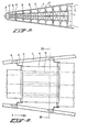
- the obstacle protector arrangement is comprised of a series of interconnected segments A provided with a nose segment A'.
- Each segment is composed of a portal-shaped support member G disposed transversely to the direction of motion X and provided for fastening an internal stabilising structure in the form of a box-like structure N.
- the support members G are slidably or rollably supported on the ground, with the exception of the rear portion which is attached to a fixed foundation L. Also, to said foundation L there are attached tie members which are to absorb the longitudinal forces occurring in the associated guide rail construction.
- the nose segment A' is provided with a guide member H which prevents displacement in any direction other than the direction of travel X (see FIGS. 8A and B).
- Each segment is provided on both sides with a flank member C which is connected to the associated support member G via an angled strip D.
- the shape and function of these strips D are illustrated in the FIGS. 10-12.
- On the bending lines of the strip it is possible to provide weakened sections, for instance bore holes. These strips afford a displacement of successive flank members past one another.
- the support members G move along, thus causing a certain degree of transversely directed deflection to occur so that things do not get stuck.
- the flank members will not deflect sidewardly, which is also in the interest of preventing damage to vehicles of third parties or injury to the latter.
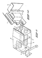
- FIG. 9 clearly shows that each box-like structure N is provided with crumple tubes B.
- the purpose of these tubes is to absorb the major portion of the kinetic energy of the colliding vehicle.
- the box-like structure N imparts stability to the entire structure, specifically at the occurrence of lateral forces (see FIGS. 13 and 14).
- the box-like structure facilitates transport and assembly of the obstacle protector arrangement.
- the construction of the nose segment A' is best apparent from the FIGS. 8A + B and 16A + B + C.
- There is an arcuate nose apron C' which may be regarded as a complement to the flank members C ending in said segment.
- the support member G' cooperates on its lower side with a foundation guide member H.
- Inside the nose apron C' there are provided several straight thin plates U (see FIGS. 16A + B + C). This enables the nose segment at the beginning of the collision to adopt the shape and/or deformation of the vehicle in a manner so that the deformative force of the nose segment is lower than the threshold value of the crumple tubes. This causes the deforming of the first box-like structure to be introduced in a proper manner (FIGS. 17A + B).
- a head-on collision may be still further differentiated into a centric, an excentric and an angular collision.
- the nose apron of the structure will deform.
- the support member G' will start sliding freely with its feet in the foundation guide member H, and the two flank members C will be pushed backwards.
- the first box-like structure will be compressed.
- the subsequent segments A will be compressed in succession. The number thereof depends upon the magnitude of the quantity of kinetic energy to be destroyed.
- the deceleration of the vehicle is determined by:
- the box-Ike structure N is so designed that the upper plate can feely bend upwards and the lower plate can freely bend downwards (see FIG 9). Such upward and downward bending quality is important so as to prevent the tubes from being struck by the lower or upper plate during impact.
- the box N is internally provided with spacer means S.
- the lower and upper plates can absorb tensile forces in the event of a lateral collision.
- the spacer' means S are also advantageous in preventing damage due to vandalism committed by passers-by (tourists) climbing upon the obstacle protector arrangement.
- the crumple tubes B in the box N are centered and fixedly secured on the frontal face by means of the spiders M. On the back side they are confined in holes provided in the back plate of the box. By premounting the crumple tubes, errors are avoided when assembling the structure.
- the support members G are so designed as to afford easy and safe mounting of the boxes N through bolt holes on the upper and lower sides, see FIG. 9.
- the wheels on the legs of the support members G ensure a smooth displacement of the support members in the longitudinal direction of the structure.
- the flank members C have a length of more than twice the length of one segment. They overlap each other, with on the back side a guide retainer E (see FIG. 7) over the next flank member.
- the flank members can slide passing one another without there being the danger of a secondary collision of the guide retainer E with the flank member of the second segment following, because they have already passed one another on the original position.
- the advantage of a great length of overlapping is that it increases the lateral and vertical stability of the whole structure.
- flank members C are connected to the support members G by means of angled strips D (FIGS. 10-12).
- the strips D afford the flank members a certain amount of movability with respect to the support member(s) G. This is necessary because in the event of a head-on collision and the successive telescoping of segments:
- a proper vertical position of the support members G is a condition for the intended behavior of the box-like structure N.
- Excentric head-on collisions are understood to be those collisions in which the longitudinal axis of the vehicle runs parallel to but spaced from the longitudinal axis of the structure.
- the longitudinal axis of the vehicle forms an angle with the longitudinal axis of the structure.
- the nose apron A' is intended to be deformed in such a way that the vehicle is not thrown back.
- the nose apron is provided with straight thin plates U (FIGS. 1 and 8). Relative to their points of fastening said plates are capable of absorbing tension but no pressure. As a result, the nose segment will be inclined to hold the vehicle. (See FIGS. 17A + B).
- the whole obstacle protector structure is to be regarded as a projecting girder with respect to the supporting foundation L (see FIG. 13).
- the box-like structure N can absorb this couple.
- Another type of collision is the lateral collision. These collisions concern impacts of collision upon the flank of the obstacle protector means.
- the whole obstacle protector arrangement forms a beam having as points of support the ground rail H and the supporting foundation L.
- the upper and lower plates of the box N act, in the tension zone, as tension absorbers.
- the crumple tubes B act, in the pressure zone, as pressure absorbers (see FIG. 14).
- the foregoing describes the obstacle protector arrangement having the box-like structure.
- This box-like structure is an essential element for increasing the stability of the structure.
- An alternative form of stabilising structure for obtaining the stability is attained by replacing the box-like structure by two crossed tension rod members F. (see FIG. 5).
- This alternative embodiment essentially functions in a manner identical with that of the form of embodiment having the box-like structure.
- This form of construction with tension rod members likewise can be realized in a V-form and a parallel form.
- the construction of the segments of this alternative embodiment is as follows. Between the support members G there are provided individual tubes B, whereupon parallel adjustment is effected by means of the tension rod members F. In the event of a lateral collision the compressive forces are again absorbed by the tubes B. Tensile forces are absorbed by the tension rod members F and the flank members C. For this purpose the flank members have been internally provided with tension absorbers J (FIG. 15). For the purpose of increasing the stability the crossed tension rod members may be connected together in the center.
Claims (7)
Priority Applications (1)
| Application Number | Priority Date | Filing Date | Title |
|---|---|---|---|
| AT81200664T ATE5828T1 (de) | 1980-06-24 | 1981-06-12 | Aufprallsicherung bei hindernissen. |
Applications Claiming Priority (2)
| Application Number | Priority Date | Filing Date | Title |
|---|---|---|---|
| NL8003653 | 1980-06-24 | ||
| NL8003653A NL8003653A (nl) | 1980-06-24 | 1980-06-24 | Obstakelbeveiliger. |
Publications (4)
| Publication Number | Publication Date |
|---|---|
| EP0042645A2 EP0042645A2 (de) | 1981-12-30 |
| EP0042645A3 EP0042645A3 (en) | 1982-08-04 |
| EP0042645B1 true EP0042645B1 (de) | 1984-01-11 |
| EP0042645B2 EP0042645B2 (de) | 1988-12-28 |
Family
ID=19835504
Family Applications (1)
| Application Number | Title | Priority Date | Filing Date |
|---|---|---|---|
| EP81200664A Expired EP0042645B2 (de) | 1980-06-24 | 1981-06-12 | Aufprallsicherung bei Hindernissen |
Country Status (6)
| Country | Link |
|---|---|
| US (1) | US4399980A (de) |
| EP (1) | EP0042645B2 (de) |
| JP (1) | JPS606410B2 (de) |
| AT (1) | ATE5828T1 (de) |
| DE (1) | DE3161882D1 (de) |
| NL (1) | NL8003653A (de) |
Cited By (1)
| Publication number | Priority date | Publication date | Assignee | Title |
|---|---|---|---|---|
| DE102007024993B4 (de) * | 2007-05-30 | 2011-02-17 | Sps Schutzplanken Gmbh | Fahrzeug-Rückhaltesystem an Verkehrswegen |
Families Citing this family (67)
| Publication number | Priority date | Publication date | Assignee | Title |
|---|---|---|---|---|
| NL8003653A (nl) * | 1980-06-24 | 1982-01-18 | Nederlanden Staat | Obstakelbeveiliger. |
| US4452431A (en) * | 1982-05-19 | 1984-06-05 | Energy Absorption Systems, Inc. | Restorable fender panel |
| FR2558186B1 (fr) * | 1984-01-13 | 1986-06-20 | France Etat | Dispositif attenuateur de chocs |
| US4674911A (en) * | 1984-06-13 | 1987-06-23 | Energy Absorption Systems, Inc. | Energy absorbing pneumatic crash cushion |
| US4635981A (en) * | 1984-10-29 | 1987-01-13 | Energy Absorption Systems, Inc. | Impact attenuating body |
| US4711481A (en) * | 1985-10-25 | 1987-12-08 | Energy Absorption Systems, Inc. | Vehicle impact attenuating device |
| US4815565A (en) * | 1986-12-15 | 1989-03-28 | Sicking Dean L | Low maintenance crash cushion end treatment |
| DE3702794A1 (de) * | 1987-01-30 | 1988-08-18 | Sps Schutzplanken Gmbh | Anpralldaempfer zum schutz von ortsfesten konstruktionen, insbesondere auf verkehrswegen |
| DE3705485C2 (de) * | 1987-02-20 | 1993-11-11 | Sps Schutzplanken Gmbh | Anpralldämpfer für Verkehrswege |
| DE3708861C2 (de) * | 1987-02-20 | 1999-03-25 | Sps Schutzplanken Gmbh | Anpralldämpfer |
| US4822208A (en) * | 1987-11-23 | 1989-04-18 | The Texas A&M University System | Advanced dynamic impact extension module |
| US4909661A (en) * | 1987-11-23 | 1990-03-20 | The Texas A&M University System | Advanced dynamic impact extension module |
| US5078366A (en) * | 1988-01-12 | 1992-01-07 | Texas A&M University System | Guardrail extruder terminal |
| US4928928A (en) * | 1988-01-12 | 1990-05-29 | The Texas A&M University System | Guardrail extruder terminal |
| US5022782A (en) * | 1989-11-20 | 1991-06-11 | Energy Absorption Systems, Inc. | Vehicle crash barrier |
| US5112028A (en) * | 1990-09-04 | 1992-05-12 | Energy Absorption Systems, Inc. | Roadway impact attenuator |
| US5192157A (en) | 1991-06-05 | 1993-03-09 | Energy Absorption Systems, Inc. | Vehicle crash barrier |
| US5217318A (en) * | 1991-08-14 | 1993-06-08 | Peppel George W | Low maintenance crash barrier for a road divider |
| US5248129A (en) * | 1992-08-12 | 1993-09-28 | Energy Absorption Systems, Inc. | Energy absorbing roadside crash barrier |
| US5494371A (en) * | 1994-11-14 | 1996-02-27 | Energy Absorption Systems, Inc. | Crash attenuator |
| US6220575B1 (en) * | 1995-01-18 | 2001-04-24 | Trn Business Trust | Anchor assembly for highway guardrail end terminal |
| US5851005A (en) * | 1997-04-15 | 1998-12-22 | Muller; Franz M. | Energy absorption apparatus |
| US6116805A (en) * | 1997-05-05 | 2000-09-12 | Gertz; David C. | Crash attenuator with a row of compressible hoops |
| US8038126B1 (en) | 1997-05-09 | 2011-10-18 | Trinity Industries, Inc. | Breakaway support post for highway guardrail end treatments |
| US6293727B1 (en) * | 1997-06-05 | 2001-09-25 | Exodyne Technologies, Inc. | Energy absorbing system for fixed roadside hazards |
| JP3964558B2 (ja) * | 1998-12-10 | 2007-08-22 | 日鐵住金建材株式会社 | 防護柵端部緩衝装置 |
| US6783116B2 (en) | 1999-01-06 | 2004-08-31 | Trn Business Trust | Guardrail end terminal assembly having at least one angle strut |
| US6398192B1 (en) | 1999-01-06 | 2002-06-04 | Trn Business Trust | Breakaway support post for highway guardrail end treatments |
| US7101111B2 (en) | 1999-07-19 | 2006-09-05 | Exodyne Technologies Inc. | Flared energy absorbing system and method |
| US7306397B2 (en) | 2002-07-22 | 2007-12-11 | Exodyne Technologies, Inc. | Energy attenuating safety system |
| US6309140B1 (en) | 1999-09-28 | 2001-10-30 | Svedala Industries, Inc. | Fender system |
| JP4282883B2 (ja) * | 2000-08-24 | 2009-06-24 | 日鐵住金建材株式会社 | 端部緩衝装置 |
| EP1313920B1 (de) | 2000-08-31 | 2012-05-30 | The Texas A & M University System | Leitplankenextruder für schienenenden |
| US8517349B1 (en) | 2000-10-05 | 2013-08-27 | The Texas A&M University System | Guardrail terminals |
| US6427983B1 (en) | 2000-10-12 | 2002-08-06 | Energy Absorption Systems, Inc. | Self-restoring highway crash attenuator |
| US6461076B1 (en) | 2001-01-03 | 2002-10-08 | Energy Absorption Systems, Inc. | Vehicle impact attenuator |
| US6536986B1 (en) * | 2001-09-24 | 2003-03-25 | Barrier Systems, Inc. | Energy absorption apparatus with collapsible modules |
| US6902150B2 (en) | 2001-11-30 | 2005-06-07 | The Texas A&M University System | Steel yielding guardrail support post |
| US6932327B2 (en) * | 2002-01-30 | 2005-08-23 | The Texas A&M University System | Cable guardrail release system |
| US6948703B2 (en) * | 2002-01-30 | 2005-09-27 | The Texas A&M University System | Locking hook bolt and method for using same |
| US6863467B2 (en) * | 2002-02-27 | 2005-03-08 | Energy Absorption Systems, Inc. | Crash cushion with deflector skin |
| US7246791B2 (en) * | 2002-03-06 | 2007-07-24 | The Texas A&M University System | Hybrid energy absorbing reusable terminal |
| US7059590B2 (en) * | 2002-06-19 | 2006-06-13 | Trn Business Trust | Impact assembly for an energy absorbing device |
| SG172475A1 (en) * | 2002-07-22 | 2011-07-28 | Exodyne Technologies Inc | Flared energy absorbing system and method |
| US20060193688A1 (en) * | 2003-03-05 | 2006-08-31 | Albritton James R | Flared Energy Absorbing System and Method |
| US20040262588A1 (en) * | 2003-06-27 | 2004-12-30 | Trn Business Trust | Variable width crash cushions and end terminals |
| DE10336713A1 (de) * | 2003-08-11 | 2005-03-17 | Michael Rossmann | Fahrzeug-Anpralldämpfer |
| US6962459B2 (en) * | 2003-08-12 | 2005-11-08 | Sci Products Inc. | Crash attenuator with cable and cylinder arrangement for decelerating vehicles |
| DE10351165B4 (de) * | 2003-11-03 | 2011-02-24 | Sps Schutzplanken Gmbh | Anpralldämpfer mit Wandelement |
| ATE458867T1 (de) * | 2003-12-09 | 2010-03-15 | Exodyne Technologies Inc | Energiedämpfungs-sicherheitssystem |
| CA2579047C (en) | 2004-09-15 | 2011-01-25 | Energy Absorption Systems, Inc. | Crash cushion |
| SI1645691T1 (sl) * | 2004-10-06 | 2007-08-31 | Tss Tech Sicherheits Systeme Gmbh | Prehodna konstrukcija |
| EP1989106B1 (de) * | 2006-02-23 | 2017-10-11 | Sikorsky Aircraft Corporation | System zur rückhaltung von flugzeugnutzdaten für innenlasten |
| JP4943913B2 (ja) * | 2007-03-28 | 2012-05-30 | 株式会社日立製作所 | 輸送機 |
| CN101480970B (zh) | 2008-01-07 | 2013-03-27 | 能量吸收系统公司 | 碰撞衰减器 |
| US7950870B1 (en) | 2008-03-28 | 2011-05-31 | Energy Absorption Systems, Inc. | Energy absorbing vehicle barrier |
| US8544715B2 (en) * | 2009-01-06 | 2013-10-01 | GM Global Technology Operations LLC | Repairing a friction stir welded assembly |
| IT1399748B1 (it) * | 2010-04-28 | 2013-05-03 | Autostrade Per L Italia S P A | Dispositivo di sicurezza stradale attenuatore di urti. |
| US8974142B2 (en) | 2010-11-15 | 2015-03-10 | Energy Absorption Systems, Inc. | Crash cushion |
| DE102012015669B4 (de) | 2012-08-09 | 2014-07-03 | Thomas Mulert | Verfahren und Vorrichtung zum Abbremsen eines außer Kontrolle geratenen Fahrzeugs |
| CN103966961B (zh) * | 2013-01-24 | 2016-06-08 | 上海船舶运输科学研究所 | 桥梁防撞消能用锚碇 |
| ITBO20130115A1 (it) | 2013-03-15 | 2014-09-16 | Impero Pasquale | Attenuatore d'urto stradale |
| US9051698B1 (en) * | 2014-06-19 | 2015-06-09 | Lindsay Transporation Solutions, Inc. | Crash attenuator apparatus |
| ITUA20162276A1 (it) * | 2016-04-04 | 2017-10-04 | Pasquale Impero | Attenuatore d'urto fissabile al lato posteriore di un camion |
| US9945084B1 (en) * | 2016-12-02 | 2018-04-17 | Lawrence Eugene Warford | Vehicle diversion barrier |
| US11136736B2 (en) * | 2019-02-04 | 2021-10-05 | Lindsay Transportation Solutions, Inc. | Anchorless crash cushion apparatus with metal nose cap |
| US20210277615A1 (en) * | 2020-03-09 | 2021-09-09 | Trinity Highway Products Llc | Crash cushion |
Family Cites Families (20)
| Publication number | Priority date | Publication date | Assignee | Title |
|---|---|---|---|---|
| US1867671A (en) * | 1931-09-08 | 1932-07-19 | Curtis A Massoll | Safety zone guard |
| DE717002C (de) * | 1933-04-26 | 1942-02-04 | Castelli Cesare | Kletterschuh |
| US2025014A (en) * | 1934-11-20 | 1935-12-17 | American Steel & Wire Co | Guard rail |
| US2088087A (en) * | 1936-05-01 | 1937-07-27 | American Rolling Mill Co | Crash bumper and the like |
| CH435357A (de) * | 1965-03-02 | 1967-05-15 | Welding Ag | Vorbaustück für eine Leitplankenanordnung |
| CH432573A (it) * | 1966-08-20 | 1967-03-31 | Holecz Ferenc | Barriera protettiva dei margini autostradali e della zona spartitraffico |
| DE1759575C3 (de) * | 1967-08-31 | 1974-10-17 | Robert 5779 Bremke Berens | Abstandhalter für Leitplanken. Ausscheidung aus: 1658647 |
| US3643924A (en) * | 1970-09-24 | 1972-02-22 | Fibco Inc | Highway safety device |
| GB1337271A (en) * | 1971-04-19 | 1973-11-14 | Titterrell W A | Shock absorbing crash barrier |
| US3845936A (en) * | 1973-05-25 | 1974-11-05 | Steel Corp | Modular crash cushion |
| US3856268A (en) * | 1973-09-17 | 1974-12-24 | Fibco Inc | Highway safety device |
| AT345883B (de) * | 1974-05-13 | 1978-10-10 | Urlberger Karl Anton Hans | Schockabsorbierendes kurvenstueck fuer leitplanken |
| US3944187A (en) * | 1974-09-13 | 1976-03-16 | Dynamics Research And Manufacturing, Inc. | Roadway impact attenuator |
| GB1492752A (en) * | 1975-06-05 | 1977-11-23 | Searle J | One-shot energy absorbing device |
| US3982734A (en) * | 1975-06-30 | 1976-09-28 | Dynamics Research And Manufacturing, Inc. | Impact barrier and restraint |
| US4101115A (en) * | 1977-02-03 | 1978-07-18 | Meinzer Lester N | Crash cushion |
| US4138093A (en) * | 1977-05-18 | 1979-02-06 | Meinzer Lester N | Guard rail cell |
| US4118014A (en) * | 1977-08-19 | 1978-10-03 | Nasa | Vehicular impact absorption system |
| US4321989A (en) * | 1980-01-22 | 1982-03-30 | Meinco Mfg. Co. | Energy absorbing impact barrier |
| NL8003653A (nl) * | 1980-06-24 | 1982-01-18 | Nederlanden Staat | Obstakelbeveiliger. |
-
1980
- 1980-06-24 NL NL8003653A patent/NL8003653A/nl not_active Application Discontinuation
-
1981
- 1981-06-12 DE DE8181200664T patent/DE3161882D1/de not_active Expired
- 1981-06-12 AT AT81200664T patent/ATE5828T1/de not_active IP Right Cessation
- 1981-06-12 EP EP81200664A patent/EP0042645B2/de not_active Expired
- 1981-06-23 US US06/276,706 patent/US4399980A/en not_active Expired - Lifetime
- 1981-06-23 JP JP56098129A patent/JPS606410B2/ja not_active Expired
Cited By (1)
| Publication number | Priority date | Publication date | Assignee | Title |
|---|---|---|---|---|
| DE102007024993B4 (de) * | 2007-05-30 | 2011-02-17 | Sps Schutzplanken Gmbh | Fahrzeug-Rückhaltesystem an Verkehrswegen |
Also Published As
| Publication number | Publication date |
|---|---|
| NL8003653A (nl) | 1982-01-18 |
| EP0042645A3 (en) | 1982-08-04 |
| EP0042645B2 (de) | 1988-12-28 |
| DE3161882D1 (en) | 1984-02-16 |
| ATE5828T1 (de) | 1984-01-15 |
| JPS606410B2 (ja) | 1985-02-18 |
| US4399980A (en) | 1983-08-23 |
| EP0042645A2 (de) | 1981-12-30 |
| JPS57133909A (en) | 1982-08-18 |
Similar Documents
| Publication | Publication Date | Title |
|---|---|---|
| EP0042645B1 (de) | Aufprallsicherung bei Hindernissen | |
| US3643924A (en) | Highway safety device | |
| US9758937B2 (en) | Energy attenuating safety system | |
| US6536985B2 (en) | Energy absorbing system for fixed roadside hazards | |
| US4838523A (en) | Energy absorbing guard rail terminal | |
| US5112028A (en) | Roadway impact attenuator | |
| US7112004B2 (en) | Hybrid energy absorbing reusable terminal | |
| JP3759259B2 (ja) | ハイウェー衝突緩衝体およびその構成要素 | |
| US6116805A (en) | Crash attenuator with a row of compressible hoops | |
| US7037029B2 (en) | Crash cushion with deflector skin | |
| CN112281718A (zh) | 一种ts级可导向防撞垫 | |
| KR101670836B1 (ko) | 가드레일 연결형 충격흡수장치 | |
| KR101267446B1 (ko) | 가드레일 전방부의 차량 충돌시 충격흡수장치 | |
| CA2546137C (en) | Energy attenuating safety system | |
| CA1292905C (en) | Energy absorbing guard rail terminal | |
| Flury et al. | Crash barrier research in the Netherlands |
Legal Events
| Date | Code | Title | Description |
|---|---|---|---|
| PUAI | Public reference made under article 153(3) epc to a published international application that has entered the european phase |
Free format text: ORIGINAL CODE: 0009012 |
|
| AK | Designated contracting states |
Designated state(s): AT BE CH DE FR GB IT LI LU NL SE |
|
| PUAL | Search report despatched |
Free format text: ORIGINAL CODE: 0009013 |
|
| AK | Designated contracting states |
Designated state(s): AT BE CH DE FR GB IT LI LU NL SE |
|
| 17P | Request for examination filed |
Effective date: 19820625 |
|
| ITF | It: translation for a ep patent filed |
Owner name: UFFICIO TECNICO ING. A. MANNUCCI |
|
| GRAA | (expected) grant |
Free format text: ORIGINAL CODE: 0009210 |
|
| AK | Designated contracting states |
Designated state(s): AT BE CH DE FR GB IT LI LU NL SE |
|
| REF | Corresponds to: |
Ref document number: 5828 Country of ref document: AT Date of ref document: 19840115 Kind code of ref document: T |
|
| REF | Corresponds to: |
Ref document number: 3161882 Country of ref document: DE Date of ref document: 19840216 |
|
| ET | Fr: translation filed | ||
| PLBI | Opposition filed |
Free format text: ORIGINAL CODE: 0009260 |
|
| 26 | Opposition filed |
Opponent name: ENERGY ABSORPTION SYSTEMS, INC. Effective date: 19841008 |
|
| PUAH | Patent maintained in amended form |
Free format text: ORIGINAL CODE: 0009272 |
|
| STAA | Information on the status of an ep patent application or granted ep patent |
Free format text: STATUS: PATENT MAINTAINED AS AMENDED |
|
| ITF | It: translation for a ep patent filed |
Owner name: UFFICIO TECNICO ING. A. MANNUCCI |
|
| 27A | Patent maintained in amended form |
Effective date: 19881228 |
|
| AK | Designated contracting states |
Kind code of ref document: B2 Designated state(s): AT BE CH DE FR GB IT LI LU NL SE |
|
| NLR2 | Nl: decision of opposition | ||
| ET3 | Fr: translation filed ** decision concerning opposition | ||
| NLR3 | Nl: receipt of modified translations in the netherlands language after an opposition procedure | ||
| ITTA | It: last paid annual fee | ||
| EPTA | Lu: last paid annual fee | ||
| EAL | Se: european patent in force in sweden |
Ref document number: 81200664.1 |
|
| PGFP | Annual fee paid to national office [announced via postgrant information from national office to epo] |
Ref country code: SE Payment date: 20000523 Year of fee payment: 20 Ref country code: LU Payment date: 20000523 Year of fee payment: 20 Ref country code: GB Payment date: 20000523 Year of fee payment: 20 Ref country code: FR Payment date: 20000523 Year of fee payment: 20 |
|
| PGFP | Annual fee paid to national office [announced via postgrant information from national office to epo] |
Ref country code: CH Payment date: 20000609 Year of fee payment: 20 Ref country code: BE Payment date: 20000609 Year of fee payment: 20 |
|
| PGFP | Annual fee paid to national office [announced via postgrant information from national office to epo] |
Ref country code: DE Payment date: 20000612 Year of fee payment: 20 |
|
| PGFP | Annual fee paid to national office [announced via postgrant information from national office to epo] |
Ref country code: AT Payment date: 20000620 Year of fee payment: 20 |
|
| PGFP | Annual fee paid to national office [announced via postgrant information from national office to epo] |
Ref country code: NL Payment date: 20000630 Year of fee payment: 20 |
|
| BE20 | Be: patent expired |
Free format text: 20010612 STAAT DER *NEDERLANDEN TE DEZEN VERTEGENWOORDIGD DOOR DE DIRECTEUR-GENERAAL VAN DE RIJKSWATERSTAAT |
|
| PG25 | Lapsed in a contracting state [announced via postgrant information from national office to epo] |
Ref country code: LI Free format text: LAPSE BECAUSE OF EXPIRATION OF PROTECTION Effective date: 20010611 Ref country code: GB Free format text: LAPSE BECAUSE OF EXPIRATION OF PROTECTION Effective date: 20010611 Ref country code: CH Free format text: LAPSE BECAUSE OF EXPIRATION OF PROTECTION Effective date: 20010611 |
|
| PG25 | Lapsed in a contracting state [announced via postgrant information from national office to epo] |
Ref country code: NL Free format text: LAPSE BECAUSE OF EXPIRATION OF PROTECTION Effective date: 20010612 Ref country code: LU Free format text: LAPSE BECAUSE OF EXPIRATION OF PROTECTION Effective date: 20010612 Ref country code: AT Free format text: LAPSE BECAUSE OF EXPIRATION OF PROTECTION Effective date: 20010612 |
|
| PG25 | Lapsed in a contracting state [announced via postgrant information from national office to epo] |
Ref country code: SE Free format text: THE PATENT HAS BEEN ANNULLED BY A DECISION OF A NATIONAL AUTHORITY Effective date: 20010629 |
|
| REG | Reference to a national code |
Ref country code: GB Ref legal event code: PE20 Effective date: 20010611 |
|
| REG | Reference to a national code |
Ref country code: CH Ref legal event code: PL |
|
| NLV7 | Nl: ceased due to reaching the maximum lifetime of a patent |
Effective date: 20010612 |
|
| EUG | Se: european patent has lapsed |
Ref document number: 81200664.1 |
|
| APAH | Appeal reference modified |
Free format text: ORIGINAL CODE: EPIDOSCREFNO |