EP0039968B1 - Wheel bearing assembly - Google Patents
Wheel bearing assembly Download PDFInfo
- Publication number
- EP0039968B1 EP0039968B1 EP81200472A EP81200472A EP0039968B1 EP 0039968 B1 EP0039968 B1 EP 0039968B1 EP 81200472 A EP81200472 A EP 81200472A EP 81200472 A EP81200472 A EP 81200472A EP 0039968 B1 EP0039968 B1 EP 0039968B1
- Authority
- EP
- European Patent Office
- Prior art keywords
- ring
- bearing
- projecting part
- bearing assembly
- inner race
- Prior art date
- Legal status (The legal status is an assumption and is not a legal conclusion. Google has not performed a legal analysis and makes no representation as to the accuracy of the status listed.)
- Expired
Links
Images

Classifications
-
- F—MECHANICAL ENGINEERING; LIGHTING; HEATING; WEAPONS; BLASTING
- F16—ENGINEERING ELEMENTS AND UNITS; GENERAL MEASURES FOR PRODUCING AND MAINTAINING EFFECTIVE FUNCTIONING OF MACHINES OR INSTALLATIONS; THERMAL INSULATION IN GENERAL
- F16C—SHAFTS; FLEXIBLE SHAFTS; ELEMENTS OR CRANKSHAFT MECHANISMS; ROTARY BODIES OTHER THAN GEARING ELEMENTS; BEARINGS
- F16C19/00—Bearings with rolling contact, for exclusively rotary movement
- F16C19/02—Bearings with rolling contact, for exclusively rotary movement with bearing balls essentially of the same size in one or more circular rows
- F16C19/14—Bearings with rolling contact, for exclusively rotary movement with bearing balls essentially of the same size in one or more circular rows for both radial and axial load
- F16C19/18—Bearings with rolling contact, for exclusively rotary movement with bearing balls essentially of the same size in one or more circular rows for both radial and axial load with two or more rows of balls
- F16C19/181—Bearings with rolling contact, for exclusively rotary movement with bearing balls essentially of the same size in one or more circular rows for both radial and axial load with two or more rows of balls with angular contact
- F16C19/183—Bearings with rolling contact, for exclusively rotary movement with bearing balls essentially of the same size in one or more circular rows for both radial and axial load with two or more rows of balls with angular contact with two rows at opposite angles
- F16C19/184—Bearings with rolling contact, for exclusively rotary movement with bearing balls essentially of the same size in one or more circular rows for both radial and axial load with two or more rows of balls with angular contact with two rows at opposite angles in O-arrangement
- F16C19/187—Bearings with rolling contact, for exclusively rotary movement with bearing balls essentially of the same size in one or more circular rows for both radial and axial load with two or more rows of balls with angular contact with two rows at opposite angles in O-arrangement with all four raceways integrated on parts other than race rings, e.g. fourth generation hubs
-
- B—PERFORMING OPERATIONS; TRANSPORTING
- B60—VEHICLES IN GENERAL
- B60B—VEHICLE WHEELS; CASTORS; AXLES FOR WHEELS OR CASTORS; INCREASING WHEEL ADHESION
- B60B27/00—Hubs
- B60B27/0005—Hubs with ball bearings
-
- B—PERFORMING OPERATIONS; TRANSPORTING
- B60—VEHICLES IN GENERAL
- B60B—VEHICLE WHEELS; CASTORS; AXLES FOR WHEELS OR CASTORS; INCREASING WHEEL ADHESION
- B60B35/00—Axle units; Parts thereof ; Arrangements for lubrication of axles
- B60B35/12—Torque-transmitting axles
- B60B35/18—Arrangement of bearings
-
- F—MECHANICAL ENGINEERING; LIGHTING; HEATING; WEAPONS; BLASTING
- F16—ENGINEERING ELEMENTS AND UNITS; GENERAL MEASURES FOR PRODUCING AND MAINTAINING EFFECTIVE FUNCTIONING OF MACHINES OR INSTALLATIONS; THERMAL INSULATION IN GENERAL
- F16C—SHAFTS; FLEXIBLE SHAFTS; ELEMENTS OR CRANKSHAFT MECHANISMS; ROTARY BODIES OTHER THAN GEARING ELEMENTS; BEARINGS
- F16C35/00—Rigid support of bearing units; Housings, e.g. caps, covers
- F16C35/04—Rigid support of bearing units; Housings, e.g. caps, covers in the case of ball or roller bearings
- F16C35/06—Mounting or dismounting of ball or roller bearings; Fixing them onto shaft or in housing
- F16C35/063—Fixing them on the shaft
-
- F—MECHANICAL ENGINEERING; LIGHTING; HEATING; WEAPONS; BLASTING
- F16—ENGINEERING ELEMENTS AND UNITS; GENERAL MEASURES FOR PRODUCING AND MAINTAINING EFFECTIVE FUNCTIONING OF MACHINES OR INSTALLATIONS; THERMAL INSULATION IN GENERAL
- F16D—COUPLINGS FOR TRANSMITTING ROTATION; CLUTCHES; BRAKES
- F16D1/00—Couplings for rigidly connecting two coaxial shafts or other movable machine elements
- F16D1/02—Couplings for rigidly connecting two coaxial shafts or other movable machine elements for connecting two abutting shafts or the like
- F16D1/027—Couplings for rigidly connecting two coaxial shafts or other movable machine elements for connecting two abutting shafts or the like non-disconnectable, e.g. involving gluing, welding or the like
-
- F—MECHANICAL ENGINEERING; LIGHTING; HEATING; WEAPONS; BLASTING
- F16—ENGINEERING ELEMENTS AND UNITS; GENERAL MEASURES FOR PRODUCING AND MAINTAINING EFFECTIVE FUNCTIONING OF MACHINES OR INSTALLATIONS; THERMAL INSULATION IN GENERAL
- F16C—SHAFTS; FLEXIBLE SHAFTS; ELEMENTS OR CRANKSHAFT MECHANISMS; ROTARY BODIES OTHER THAN GEARING ELEMENTS; BEARINGS
- F16C2226/00—Joining parts; Fastening; Assembling or mounting parts
- F16C2226/30—Material joints
- F16C2226/36—Material joints by welding
-
- F—MECHANICAL ENGINEERING; LIGHTING; HEATING; WEAPONS; BLASTING
- F16—ENGINEERING ELEMENTS AND UNITS; GENERAL MEASURES FOR PRODUCING AND MAINTAINING EFFECTIVE FUNCTIONING OF MACHINES OR INSTALLATIONS; THERMAL INSULATION IN GENERAL
- F16C—SHAFTS; FLEXIBLE SHAFTS; ELEMENTS OR CRANKSHAFT MECHANISMS; ROTARY BODIES OTHER THAN GEARING ELEMENTS; BEARINGS
- F16C2326/00—Articles relating to transporting
- F16C2326/01—Parts of vehicles in general
- F16C2326/02—Wheel hubs or castors
-
- F—MECHANICAL ENGINEERING; LIGHTING; HEATING; WEAPONS; BLASTING
- F16—ENGINEERING ELEMENTS AND UNITS; GENERAL MEASURES FOR PRODUCING AND MAINTAINING EFFECTIVE FUNCTIONING OF MACHINES OR INSTALLATIONS; THERMAL INSULATION IN GENERAL
- F16D—COUPLINGS FOR TRANSMITTING ROTATION; CLUTCHES; BRAKES
- F16D3/00—Yielding couplings, i.e. with means permitting movement between the connected parts during the drive
- F16D3/16—Universal joints in which flexibility is produced by means of pivots or sliding or rolling connecting parts
- F16D3/20—Universal joints in which flexibility is produced by means of pivots or sliding or rolling connecting parts one coupling part entering a sleeve of the other coupling part and connected thereto by sliding or rolling members
- F16D3/22—Universal joints in which flexibility is produced by means of pivots or sliding or rolling connecting parts one coupling part entering a sleeve of the other coupling part and connected thereto by sliding or rolling members the rolling members being balls, rollers, or the like, guided in grooves or sockets in both coupling parts
- F16D3/223—Universal joints in which flexibility is produced by means of pivots or sliding or rolling connecting parts one coupling part entering a sleeve of the other coupling part and connected thereto by sliding or rolling members the rolling members being balls, rollers, or the like, guided in grooves or sockets in both coupling parts the rolling members being guided in grooves in both coupling parts
- F16D2003/22326—Attachments to the outer joint member, i.e. attachments to the exterior of the outer joint member or to the shaft of the outer joint member
Definitions
- the invention relates to a wheel bearing assembly
- a preloaded and adjusted rolling bearing unit which consists of an inner-and outer-ring each being homogeneous with an attachment flange and between which two rows of rolling elements are provided that are sealed-off against dirt and to which unit a homokinetic coupling is connected by welding the outer-ring of said coupling comprising a projecting part positioned inside the bearing and restricted by a shoulder which bears against the end-part of said bearing inner-ring.
- a bearing assembly of this kind is disclosed in the US patent 3,757,883 and is primarily used for mounting the stearable wheels of a vehicle, in particular a vehicle with front-wheel drive, the assembly being ready for use as such and requiring only to be installed, since the bearing is pre- loaded, adjusted, furnished with a lubricant and sealed beforehand.
- the assembly is fastened to the vehicle by the attachment flange of the outer race, while the wheel hub is connected to the flange-of the inner race.
- connection thus obtained between the bearing and the homokinetic coupling is comparatively weak, since the weld can only be made between the very end-part of the projection part of the coupling housing and a relative small part of the inner-ring, since the pitch diameter of the race ways is at least twice the overall axial width of the annular members, which means that for this type of bearing dimensions the cylindrical end-part of the coupling housing and the cooperating inner-ring must have a closely fit otherwise mis-alignment between both parts having such a large diameter will be introduced and thus mal-functioning fostered.
- a weld can only be made at the end-part of the cylindrical coupling housing abutting against the inner-ring.
- this known connection (US patent 3,757,883 and UK patent 1 298 552) requires high tolerances of the surfaces to be connected.
- the object of the invention is to provide a bearing assembly of the type mentioned, having a very strong connection produced by welding between and positioning of bearing and homokinetic coupling parts.
- said projecting part is tapered to converge outward relative to the outer-ring of said homokinetic coupling and the portion of the interior surface of the inner-ring of the bearing that encloses said projection is correspondingly tapered to diverge outward said projecting part being connected to said inner-ring by a weld encased between said bearing inner-ring and said projecting part, the weld having been made by electron beam or laser welding which energy beam has been directed from the open end of said inner-ring.
- connection thus produced between the bearing and the homokinetic coupling is very strong, since the tapered execution of both connection parts enables a larger connection-surface than is possible in the known assemblies whereby the closely fit between the cylindrical projecting part of the coupling housing part and bearing inner-ring prevents a deep laying weld between said parts.
- the claimed design on the contrary introduces the making of such a deep laying weld that obviously improves the connection.
- At least one set of mutually cooperating projections and recesses are provided on the exterior surface of the projecting part and the interior surface of the portion of the inner race enclosing that part.
- an electronic measuring device is arranged, capable of measuring and indicating the working of the assembled parts.
- a recess may also be made in the inside wall of the inner race for securing a fastening means for a hub cap or other wheel ornament.
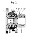
- the assembly comprises a ball bearing 1 and a homokinetic coupling 2 connected therewith.
- the bearing comprises an outer race ring 3 with a flange 4 integral therewith and an inner race ring 5 with a flange 6 integral therewith.
- two rows of rolling elements 7 are adjusted and held separate from each other by a cage 8.
- sealing members 9 and 10 are also on either side of said rolling elements 7, so that the bearing 1 forms a pre-loaded, adjusted, lubricated and sealed unit.
- the outer ring 11 From the homokinetic coupling 2, only the outer ring 11 is shown, having a projecting portion 12 situated within the inner race 5 of the bearing, which portion 12 converges tapered outward relative to the ring 11.
- the portion of the interior surface of the inner race 5 that encloses this projecting portion 12 is correspondingly tapered, while a weld 13 produced by an electron or laser beam connects the projecting portion 12 to the inner race 5.
- the projection portion 12 positioned inside the bearing is restricted thereto by a shoulder 12a which bears against the end-part 5a of the bearing inner-ring 5.
- projections 14 of triangular cross section may be formed additionally on the periphery of the projecting portion 12, to engage matching recesses in the interior surface of the inner race.
- an electronic measuring means is arranged, for example comprising an electronic voltage comparator 16 and a chemical indicator 17, which changes color in each instance on occurrence of a shock impulse above a certain threshold value, so that the extent to which, within a given lapse of time, the indicator 17 has changed color, is a measure of the action of the assembly.
- a hub cap or other trim 18 can be secured to the fellow of the wheel with the aid of a fastening means (for example a bolt) located in a groove 19 in the bore of the inner race and capable of being fixed therein.
- a fastening means for example a bolt located in a groove 19 in the bore of the inner race and capable of being fixed therein.
- a projection on the hub cap 18 itself is the fastening means.
Landscapes
- Engineering & Computer Science (AREA)
- General Engineering & Computer Science (AREA)
- Mechanical Engineering (AREA)
- Rolling Contact Bearings (AREA)
- Welding Or Cutting Using Electron Beams (AREA)
- Laser Beam Processing (AREA)
Applications Claiming Priority (2)
| Application Number | Priority Date | Filing Date | Title |
|---|---|---|---|
| NL8002688A NL8002688A (nl) | 1980-05-09 | 1980-05-09 | Lagersamenstel. |
| NL8002688 | 1980-09-05 |
Publications (2)
| Publication Number | Publication Date |
|---|---|
| EP0039968A1 EP0039968A1 (en) | 1981-11-18 |
| EP0039968B1 true EP0039968B1 (en) | 1987-04-22 |
Family
ID=19835274
Family Applications (1)
| Application Number | Title | Priority Date | Filing Date |
|---|---|---|---|
| EP81200472A Expired EP0039968B1 (en) | 1980-05-09 | 1981-05-01 | Wheel bearing assembly |
Country Status (9)
| Country | Link |
|---|---|
| US (1) | US4550237A (ja) |
| EP (1) | EP0039968B1 (ja) |
| JP (2) | JPS571826A (ja) |
| AU (1) | AU541367B2 (ja) |
| BR (1) | BR8102790A (ja) |
| CA (1) | CA1189556A (ja) |
| DE (1) | DE3176126D1 (ja) |
| MX (1) | MX155453A (ja) |
| NL (1) | NL8002688A (ja) |
Families Citing this family (19)
| Publication number | Priority date | Publication date | Assignee | Title |
|---|---|---|---|---|
| JP2625724B2 (ja) * | 1987-05-25 | 1997-07-02 | ミノルタ株式会社 | 画像形成方法 |
| FR2745235B1 (fr) * | 1996-02-27 | 2000-04-28 | Guimbretiere Pierre | Accouplement en rotation d'une bride de roue a un organe de sortie d'un joint d'articulation d'une transmission |
| FR2745234B1 (fr) * | 1996-02-27 | 1998-05-15 | Guimbretiere Pierre | Accouplement en rotation d'une bride de roue a un organe de sortie d'un joint d'articulation d'une transmission |
| FR2754033B1 (fr) * | 1996-09-30 | 2003-02-21 | Valeo | Double volant a roulement a billes, notamment pour vehicule automobile |
| FR2762056B1 (fr) * | 1997-04-15 | 1999-05-14 | Skf France | Palier a roulement a capteur d'informations |
| JPH11230177A (ja) | 1998-02-10 | 1999-08-27 | Tok Bearing Co Ltd | フランジ付き小形ベアリング |
| US6422947B1 (en) | 2000-02-11 | 2002-07-23 | Visteon Global Technologies, Inc. | Driveshaft bearing assembly |
| JP4474774B2 (ja) * | 2000-05-31 | 2010-06-09 | 日本精工株式会社 | 車輪駆動用ユニット |
| JP4636959B2 (ja) * | 2005-07-08 | 2011-02-23 | 株式会社岡村製作所 | 間仕切パネル装置 |
| JP4713254B2 (ja) * | 2005-07-08 | 2011-06-29 | 株式会社岡村製作所 | 間仕切パネル装置 |
| JP4713255B2 (ja) * | 2005-07-08 | 2011-06-29 | 株式会社岡村製作所 | 間仕切パネル装置 |
| DE102005049454A1 (de) * | 2005-10-15 | 2007-04-19 | Schaeffler Kg | Lagereinheit, vorzugsweise Radlagereinheit für ein Kraftfahrzeug, sowie Verfahren zur Herstellung einer Lagereinheit |
| CN100413725C (zh) * | 2006-10-30 | 2008-08-27 | 孔素芳 | 汽车轮毂单元与万向节组合总成 |
| JP5172183B2 (ja) * | 2007-03-20 | 2013-03-27 | Ntn株式会社 | 等速自在継手の外側継手部材 |
| DE102007050215A1 (de) * | 2007-10-04 | 2009-04-09 | Schaeffler Kg | Radlagerung für Kraftfahrzeuge |
| FR2990731B1 (fr) * | 2012-05-16 | 2014-05-02 | Eurocopter France | Dispositif de liaison a rotule |
| US9638198B2 (en) * | 2015-02-24 | 2017-05-02 | Borgwarner Inc. | Shaftless turbocharger |
| FR3074239B1 (fr) * | 2017-11-30 | 2020-02-21 | Ntn-Snr Roulements | Ensemble tournant pour roue de vehicule, instrumente avec un dispositif indicateur de choc |
| KR102295186B1 (ko) * | 2019-09-24 | 2021-09-01 | (주)세고스 | 베어링 조립체 |
Family Cites Families (10)
| Publication number | Priority date | Publication date | Assignee | Title |
|---|---|---|---|---|
| GB1298552A (en) * | 1968-12-20 | 1972-12-06 | Skefko Ball Bearing Company Lt | Improvements in wheel hub bearing assemblies |
| GB1323686A (en) * | 1969-11-26 | 1973-07-18 | Secr Defence | Welding |
| US3757883A (en) * | 1971-02-03 | 1973-09-11 | Skf Nv | Wheel support for an engine propelled road vehicle |
| GB1358842A (en) * | 1971-07-14 | 1974-07-03 | Skf Uk Ltd | Wheel hub bearing assemblies |
| NL169630C (nl) * | 1972-04-18 | 1982-08-02 | Skf Ind Trading & Dev | Uitwisselbare lagereenheid. |
| DE2522841A1 (de) * | 1975-05-23 | 1976-12-02 | Loehr & Bromkamp Gmbh | Anordnung einer ueber ein gleichlaufdrehgelenk antreibbaren radnabe |
| JPS5315972A (en) * | 1976-07-28 | 1978-02-14 | Oshima Youhei | Automatically covering device for drying unit |
| FR2408473A1 (fr) * | 1977-11-09 | 1979-06-08 | Roulements Soc Nouvelle | Moyeu de roue entraine par un joint homocinetique |
| US4330911A (en) * | 1979-11-29 | 1982-05-25 | Skf Industrial Trading & Development Co. B.V. | Process for production of an object consisting of at least two parts movable relative to each other, one of which is substantially enclosed within the other |
| DE3009199A1 (de) * | 1980-03-11 | 1981-09-17 | Löhr & Bromkamp GmbH, 6050 Offenbach | Lagerungsanordnung einer ueber ein gleichlaufdrehgelenk antreibbaren radnabe |
-
1980
- 1980-05-09 NL NL8002688A patent/NL8002688A/nl not_active Application Discontinuation
-
1981
- 1981-05-01 EP EP81200472A patent/EP0039968B1/en not_active Expired
- 1981-05-01 DE DE8181200472T patent/DE3176126D1/de not_active Expired
- 1981-05-06 BR BR8102790A patent/BR8102790A/pt not_active IP Right Cessation
- 1981-05-07 AU AU70232/81A patent/AU541367B2/en not_active Ceased
- 1981-05-08 CA CA000377170A patent/CA1189556A/en not_active Expired
- 1981-05-08 JP JP6843781A patent/JPS571826A/ja active Pending
- 1981-05-11 MX MX187238A patent/MX155453A/es unknown
-
1983
- 1983-10-13 US US06/541,378 patent/US4550237A/en not_active Expired - Fee Related
-
1990
- 1990-08-16 JP JP1990085901U patent/JPH0330623U/ja active Pending
Also Published As
| Publication number | Publication date |
|---|---|
| EP0039968A1 (en) | 1981-11-18 |
| JPS571826A (en) | 1982-01-07 |
| JPH0330623U (ja) | 1991-03-26 |
| MX155453A (es) | 1988-03-11 |
| CA1189556A (en) | 1985-06-25 |
| US4550237A (en) | 1985-10-29 |
| DE3176126D1 (en) | 1987-05-27 |
| NL8002688A (nl) | 1981-12-01 |
| BR8102790A (pt) | 1982-01-26 |
| AU541367B2 (en) | 1985-01-03 |
| AU7023281A (en) | 1981-11-12 |
Similar Documents
| Publication | Publication Date | Title |
|---|---|---|
| EP0039968B1 (en) | Wheel bearing assembly | |
| US4571099A (en) | Bearing assembly for wheel hub driven by a universal joint | |
| KR950003068B1 (ko) | 감마 베어링 조립체 | |
| US6464399B1 (en) | Hub assembly for automotive vehicles | |
| US4427085A (en) | Wheel support assembly for a motor vehicle | |
| US4668111A (en) | Roller bearing unit | |
| US4433932A (en) | Roller bearings installed without clearance and preloaded | |
| US4726696A (en) | Molded rubber seal for bearing and stamping assembly | |
| US20050157965A1 (en) | Bearing with tapered rolling bodies provided with a sealing device | |
| US5540192A (en) | Integrated water pump assembly for internal combustion engines | |
| US4564243A (en) | Hub bearing unit | |
| US6974259B2 (en) | Bearing device for vehicle | |
| US5121998A (en) | Bearing assembly capable of monitoring angular velocity | |
| US5468072A (en) | System and method for supporting a shaft or axle in a support component | |
| US5140261A (en) | Bearing apparatus for a driven shaft of an automobile having a rotational speed detector | |
| GB2109874A (en) | Wheel bearing unit | |
| US4958947A (en) | Axial rolling bearing | |
| JP4643237B2 (ja) | 車輪用軸受装置 | |
| JP2601238Y2 (ja) | 車輪用軸受の密封装置 | |
| US6808311B2 (en) | Vehicle wheel bearing | |
| US20070204461A1 (en) | Method of manufacturing bearing device for a wheel | |
| CN112659812B (zh) | 带发电机的轮毂单元轴承 | |
| GB1395894A (en) | Bearing assemblies | |
| US6311985B1 (en) | Integral yoke and slinger | |
| JP2002195280A (ja) | 車軸用軸受装置 |
Legal Events
| Date | Code | Title | Description |
|---|---|---|---|
| PUAI | Public reference made under article 153(3) epc to a published international application that has entered the european phase |
Free format text: ORIGINAL CODE: 0009012 |
|
| AK | Designated contracting states |
Designated state(s): DE FR GB IT NL SE |
|
| 17P | Request for examination filed |
Effective date: 19820521 |
|
| GRAA | (expected) grant |
Free format text: ORIGINAL CODE: 0009210 |
|
| AK | Designated contracting states |
Kind code of ref document: B1 Designated state(s): DE FR GB IT NL SE |
|
| ITF | It: translation for a ep patent filed |
Owner name: STUDIO TORTA SOCIETA' SEMPLICE |
|
| REF | Corresponds to: |
Ref document number: 3176126 Country of ref document: DE Date of ref document: 19870527 |
|
| ET | Fr: translation filed | ||
| PLBE | No opposition filed within time limit |
Free format text: ORIGINAL CODE: 0009261 |
|
| STAA | Information on the status of an ep patent application or granted ep patent |
Free format text: STATUS: NO OPPOSITION FILED WITHIN TIME LIMIT |
|
| 26N | No opposition filed | ||
| PGFP | Annual fee paid to national office [announced via postgrant information from national office to epo] |
Ref country code: FR Payment date: 19920413 Year of fee payment: 12 |
|
| PGFP | Annual fee paid to national office [announced via postgrant information from national office to epo] |
Ref country code: GB Payment date: 19920416 Year of fee payment: 12 Ref country code: DE Payment date: 19920416 Year of fee payment: 12 |
|
| PGFP | Annual fee paid to national office [announced via postgrant information from national office to epo] |
Ref country code: SE Payment date: 19920427 Year of fee payment: 12 |
|
| ITTA | It: last paid annual fee | ||
| PGFP | Annual fee paid to national office [announced via postgrant information from national office to epo] |
Ref country code: NL Payment date: 19920531 Year of fee payment: 12 |
|
| PG25 | Lapsed in a contracting state [announced via postgrant information from national office to epo] |
Ref country code: GB Effective date: 19930501 |
|
| PG25 | Lapsed in a contracting state [announced via postgrant information from national office to epo] |
Ref country code: SE Effective date: 19930502 |
|
| PG25 | Lapsed in a contracting state [announced via postgrant information from national office to epo] |
Ref country code: NL Effective date: 19931201 |
|
| GBPC | Gb: european patent ceased through non-payment of renewal fee |
Effective date: 19930501 |
|
| NLV4 | Nl: lapsed or anulled due to non-payment of the annual fee | ||
| PG25 | Lapsed in a contracting state [announced via postgrant information from national office to epo] |
Ref country code: FR Effective date: 19940131 |
|
| PG25 | Lapsed in a contracting state [announced via postgrant information from national office to epo] |
Ref country code: DE Effective date: 19940201 |
|
| REG | Reference to a national code |
Ref country code: FR Ref legal event code: ST |
|
| EUG | Se: european patent has lapsed |
Ref document number: 81200472.9 Effective date: 19931210 |