EP0038532B1 - Engine mounting structure - Google Patents
Engine mounting structure Download PDFInfo
- Publication number
- EP0038532B1 EP0038532B1 EP81102921A EP81102921A EP0038532B1 EP 0038532 B1 EP0038532 B1 EP 0038532B1 EP 81102921 A EP81102921 A EP 81102921A EP 81102921 A EP81102921 A EP 81102921A EP 0038532 B1 EP0038532 B1 EP 0038532B1
- Authority
- EP
- European Patent Office
- Prior art keywords
- coupling member
- engine
- mounting structure
- resilient block
- sections
- Prior art date
- Legal status (The legal status is an assumption and is not a legal conclusion. Google has not performed a legal analysis and makes no representation as to the accuracy of the status listed.)
- Expired
Links
Images
Classifications
-
- F—MECHANICAL ENGINEERING; LIGHTING; HEATING; WEAPONS; BLASTING
- F16—ENGINEERING ELEMENTS AND UNITS; GENERAL MEASURES FOR PRODUCING AND MAINTAINING EFFECTIVE FUNCTIONING OF MACHINES OR INSTALLATIONS; THERMAL INSULATION IN GENERAL
- F16F—SPRINGS; SHOCK-ABSORBERS; MEANS FOR DAMPING VIBRATION
- F16F7/00—Vibration-dampers; Shock-absorbers
- F16F7/10—Vibration-dampers; Shock-absorbers using inertia effect
- F16F7/104—Vibration-dampers; Shock-absorbers using inertia effect the inertia member being resiliently mounted
- F16F7/108—Vibration-dampers; Shock-absorbers using inertia effect the inertia member being resiliently mounted on plastics springs
-
- F—MECHANICAL ENGINEERING; LIGHTING; HEATING; WEAPONS; BLASTING
- F16—ENGINEERING ELEMENTS AND UNITS; GENERAL MEASURES FOR PRODUCING AND MAINTAINING EFFECTIVE FUNCTIONING OF MACHINES OR INSTALLATIONS; THERMAL INSULATION IN GENERAL
- F16F—SPRINGS; SHOCK-ABSORBERS; MEANS FOR DAMPING VIBRATION
- F16F1/00—Springs
- F16F1/36—Springs made of rubber or other material having high internal friction, e.g. thermoplastic elastomers
- F16F1/42—Springs made of rubber or other material having high internal friction, e.g. thermoplastic elastomers characterised by the mode of stressing
- F16F1/52—Springs made of rubber or other material having high internal friction, e.g. thermoplastic elastomers characterised by the mode of stressing loaded in combined stresses
- F16F1/54—Springs made of rubber or other material having high internal friction, e.g. thermoplastic elastomers characterised by the mode of stressing loaded in combined stresses loaded in compression and shear
-
- B—PERFORMING OPERATIONS; TRANSPORTING
- B60—VEHICLES IN GENERAL
- B60G—VEHICLE SUSPENSION ARRANGEMENTS
- B60G2202/00—Indexing codes relating to the type of spring, damper or actuator
- B60G2202/20—Type of damper
- B60G2202/25—Dynamic damper
-
- F—MECHANICAL ENGINEERING; LIGHTING; HEATING; WEAPONS; BLASTING
- F16—ENGINEERING ELEMENTS AND UNITS; GENERAL MEASURES FOR PRODUCING AND MAINTAINING EFFECTIVE FUNCTIONING OF MACHINES OR INSTALLATIONS; THERMAL INSULATION IN GENERAL
- F16F—SPRINGS; SHOCK-ABSORBERS; MEANS FOR DAMPING VIBRATION
- F16F2236/00—Mode of stressing of basic spring or damper elements or devices incorporating such elements
- F16F2236/12—Mode of stressing of basic spring or damper elements or devices incorporating such elements loaded in combined stresses
- F16F2236/123—Mode of stressing of basic spring or damper elements or devices incorporating such elements loaded in combined stresses loaded in compression and shear
Definitions
- the present invention relates to an engine mounting structure for mounting an automotive engine on the body structure of an automotive vehicle, comprising at least one shock and vibration insulating unit which comprises a first coupling member connected to the body structure of the vehicle, a second coupling member connected to the body structure of the engine and spaced apart from the first coupling member, a main resilient block connected to the first and second coupling member and a vibration cancelling means comprising at least one combination of a mass member, a first auxiliary resilient block connected to the first coupling member and a second auxiliary resilient block connected to the second coupling member.
- the resilient block is connected between the body structure of the vehicle and an engine-side-bracket secured to the engine mounted on the vehicle body structure.
- the resilient block is usually designed to have a relatively large spring constant so as to be capable of taking up the vibrations of the engine under medium-speed cruising conditions of the vehicle.
- the engine tends to produce vibrations at frequencies within a certain relatively low range which tend to cause production of stifled, droning noises in the vehicle cabin.
- the resilient block of the shock and vibration insulating unit would be required to have an increased weight leading to an enlarged construction of the engine mounting structure as a whole. Therefore, a mass member is connected via a first and second auxiliary resilient block to the first and second coupling member, respectively, for damping the above vibrations.
- the main resilient block consists of two substantially similar sections spaced apart from each other and in which said first and second coupling members have respective inner faces securely attached to said sections, said first and second auxiliary resilient blocks being securely attached to the inner faces of said first and second coupling members, respectively and being spaced apart from each other and from said sections, said mass member having a portion interposed between said first and second auxiliary resilient blocks.
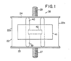
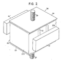
- Figs. 1 and 2 of the drawings show a shock and vibration insulation unit 38 which forms part of a preferred embodiment of the engine mounting structure according to the present invention.
- the shock and vibration insulating unit 38 constitutes one of the two such shock and vibration insulating units of an engine mounting structure embodying the present invention.
- the shock and vibration insulating unit 38 comprises a main resilient block 22 consisting of two independent sections 22a and 22b which are spaced apart substantially in parallel from each other and each of which has substantially parallel opposite end faces.
- the shock and vibration insulating unit 38 further comprises a rigid first or lower coupling member 23 securely attached to one of the end faces of each of the sections 22a and 22b, and a rigid second or upper coupling member 24 securely attached to the other end faces of the sections 22a and 22b.
- the resilient block 22 thus composed of the two sections 22a and 22b is constructed of a suitable resilient material such as rubber having a predetermined spring constant.
- the shock and vibration insulating unit 38 shown in Figs. 1 and 2 further comprises vibration cancelling means comprising first and second or lower and upper auxiliary resilient blocks 39 and 40 positioned intermediate between the sections 22a and 22b of the main resilient block 22 and each having substantially parallel opposite end faces.
- the lower auxiliary resilient block 39 is securely attached over one of its opposite end faces to the inner face of the lower coupling member 23 and, likewise, the upper auxiliary resilient block 40 is securely attached over one of its end faces to the inner face of the upper coupling member 24.
- the lower and upper auxiliary resilient blocks 39 and 40 are sidewise spaced apart from the sections 22a and 22b of the main resilient block 22 and has the other end faces thereof spaced apart substantially from each other as will be seen from the illustration by broken lines in Fig. 1.
- Each of the auxiliary resilient blocks 39 and 40 is also constructed of a suitable resilient material such as compressible rubber having a predetermined spring constant.
- a compressible rubber as the material of the resilient blocks 39 and 40 will add to the durability and accordingly the service life of the shock and vibration insulating unit 38 as a whole.
- the vibration cancelling means of the shock and vibration insulating unit 38 illustrated in Figs. 1 and 2 further comprises a pair of mass members 41 and 41' each having a lug portion 42 (Fig. 1) interposed under compression between the lower and upper auxiliary resilient blocks 39 and 40.
- the lower auxiliary resilient block 39 structurally intervenes between the lower coupling member 23 and each of the mass members 41 and 41' and, likewise, the upper auxiliary resilient block 40 structurally intervenes between the upper coupling member 24 and each of the mass members 41 and 41'.
- Each of the mass members 41 and 41' has a predetermined mass.
- the shock and vibration insulating unit 38 thus constructed is securely connected between one of the bracket portions of a suitable cross member such as a front suspension member of a vehicle body structure by means of, for example, a bolt 27 projecting from the lower coupling member 23 and further to the body structure of an automotive engine by means of, for example, a bolt 29 projecting from the upper coupling member 24 and screwed into one of engine-side bracket members secured to the engine body structure.
- a suitable cross member such as a front suspension member of a vehicle body structure by means of, for example, a bolt 27 projecting from the lower coupling member 23 and further to the body structure of an automotive engine by means of, for example, a bolt 29 projecting from the upper coupling member 24 and screwed into one of engine-side bracket members secured to the engine body structure.
Landscapes
- Engineering & Computer Science (AREA)
- General Engineering & Computer Science (AREA)
- Mechanical Engineering (AREA)
- Health & Medical Sciences (AREA)
- Child & Adolescent Psychology (AREA)
- Vibration Prevention Devices (AREA)
- Arrangement Or Mounting Of Propulsion Units For Vehicles (AREA)
Applications Claiming Priority (2)
| Application Number | Priority Date | Filing Date | Title |
|---|---|---|---|
| JP51349/80 | 1980-04-17 | ||
| JP55051349A JPS6015807B2 (ja) | 1980-04-17 | 1980-04-17 | エンジンのマウンテイング装置 |
Publications (3)
| Publication Number | Publication Date |
|---|---|
| EP0038532A2 EP0038532A2 (en) | 1981-10-28 |
| EP0038532A3 EP0038532A3 (en) | 1982-05-26 |
| EP0038532B1 true EP0038532B1 (en) | 1985-07-24 |
Family
ID=12884441
Family Applications (1)
| Application Number | Title | Priority Date | Filing Date |
|---|---|---|---|
| EP81102921A Expired EP0038532B1 (en) | 1980-04-17 | 1981-04-15 | Engine mounting structure |
Country Status (5)
| Country | Link |
|---|---|
| US (1) | US4445662A (ja) |
| EP (1) | EP0038532B1 (ja) |
| JP (1) | JPS6015807B2 (ja) |
| AU (1) | AU528429B2 (ja) |
| DE (1) | DE3171462D1 (ja) |
Families Citing this family (17)
| Publication number | Priority date | Publication date | Assignee | Title |
|---|---|---|---|---|
| US4403762A (en) * | 1981-02-20 | 1983-09-13 | General Motors Corporation | Low force transmissibility mount |
| US4494723A (en) * | 1982-12-28 | 1985-01-22 | Toyota Jidosha Kabushiki Kaisha | Device for mounting an engine on a vehicle body |
| US4537381A (en) * | 1982-12-28 | 1985-08-27 | Toyota Jidosha Kabushiki Kaisha | Engine mount |
| EP0117139B1 (en) * | 1983-02-17 | 1989-10-18 | Honda Giken Kogyo Kabushiki Kaisha | Fluid-sealed engine mounting |
| JPS6014627A (ja) * | 1983-07-06 | 1985-01-25 | Nissan Motor Co Ltd | サスペンションメンバの筒状弾性ブッシュ |
| DE3402401A1 (de) * | 1984-01-25 | 1985-07-25 | Adam Opel AG, 6090 Rüsselsheim | Lageranordnung, insbesondere motorlager fuer kraftfahrzeuge |
| US4610420A (en) * | 1984-02-16 | 1986-09-09 | Nissan Motor Company, Limited | Apparatus for mounting power unit |
| DE3431324A1 (de) * | 1984-08-25 | 1986-03-06 | Adam Opel AG, 6090 Rüsselsheim | Anordnung zur lagerung eines motors am fahrwerk eines kraftfahrzeuges |
| DE3436822C2 (de) * | 1984-10-06 | 1986-10-23 | Adam Opel AG, 6090 Rüsselsheim | Lageranordnung, insbesondere zur Lagerung eines Motors am Fahrwerk eines Kraftfahrzeuges |
| GB2186946A (en) * | 1986-02-25 | 1987-08-26 | Rank Taylor Hobson Ltd | Vibration isolation means |
| US4842258A (en) * | 1987-04-17 | 1989-06-27 | Toyota Jidosha Kabushiki Kaisha | Composite engine mount |
| JP2542521B2 (ja) * | 1987-12-17 | 1996-10-09 | ライオン株式会社 | 容器入り高嵩密度粒状洗剤 |
| DE4316487A1 (de) * | 1993-05-17 | 1994-11-24 | Metzeler Gimetall Ag | Anordnung zur frequenzselektiven Minimierung der dynamischen Federsteifigkeit eines Elastomerlagers |
| US5687948A (en) * | 1995-09-26 | 1997-11-18 | Lord Corporation | Vibration isolation system including a passive tuned vibration absorber |
| JP4780991B2 (ja) * | 2005-03-29 | 2011-09-28 | 東海ゴム工業株式会社 | エンジンマウントおよびそれを用いたパワーユニットの防振支持構造 |
| AT9776U1 (de) * | 2006-10-04 | 2008-03-15 | Pustelnik Philipp Dipl Ing | Element zum abstützen schwingungsfähiger aggregate |
| EP3798029B1 (en) * | 2019-09-18 | 2023-08-09 | CNH Industrial Italia S.p.A. | Suspension arrangement for a work vehicle |
Family Cites Families (12)
| Publication number | Priority date | Publication date | Assignee | Title |
|---|---|---|---|---|
| FR1135312A (fr) * | 1955-06-21 | 1957-04-26 | Anciens Etablissements Panhard | Procédé pour améliorer l'isolement anti-vibratoire conféré par un dispositif isolant, absorbant ou élastique, quelconque |
| GB1026358A (en) * | 1963-01-11 | 1966-04-20 | Rover Co Ltd | Suspension of machinery and other bodies |
| US3322379A (en) * | 1964-11-03 | 1967-05-30 | Kaman Aircraft Corp | Dynamic antiresonant vibration isolator |
| US3388772A (en) * | 1966-06-16 | 1968-06-18 | Continental Motors Corp | Vibration absorber |
| FR1520695A (fr) * | 1967-03-01 | 1968-04-12 | Renault | Dispositif antivibratoire pour moteurs ou machines fixes ou mobiles |
| US3445080A (en) * | 1967-05-26 | 1969-05-20 | Kaman Corp | Dynamic antiresonant vibration isolator |
| FR2054774A5 (ja) * | 1969-07-25 | 1971-05-07 | Peugeot & Renault | |
| DE2807160A1 (de) * | 1978-02-20 | 1979-08-30 | Continental Gummi Werke Ag | Lagerelement zum elastischen unterstuetzen insbesondere von motoren in kraftfahrzeugen |
| FR2431639A1 (fr) * | 1978-07-19 | 1980-02-15 | Ouest Cie | Support elastique antivibratoire a dephaseur incorpore |
| FR2444852A1 (fr) * | 1978-12-19 | 1980-07-18 | Peugeot | Cale elastique de suspension, a filtrage de vibrations de frequence elevee |
| JPS5690725A (en) * | 1979-12-20 | 1981-07-23 | Nissan Motor Co Ltd | Mounting device for engine |
| JPS56108307A (en) * | 1980-02-01 | 1981-08-27 | Nissan Motor Co Ltd | Device for supporting engine |
-
1980
- 1980-04-17 JP JP55051349A patent/JPS6015807B2/ja not_active Expired
-
1981
- 1981-04-07 US US06/251,854 patent/US4445662A/en not_active Expired - Lifetime
- 1981-04-13 AU AU69447/81A patent/AU528429B2/en not_active Ceased
- 1981-04-15 DE DE8181102921T patent/DE3171462D1/de not_active Expired
- 1981-04-15 EP EP81102921A patent/EP0038532B1/en not_active Expired
Also Published As
| Publication number | Publication date |
|---|---|
| US4445662A (en) | 1984-05-01 |
| AU528429B2 (en) | 1983-04-28 |
| JPS6015807B2 (ja) | 1985-04-22 |
| EP0038532A3 (en) | 1982-05-26 |
| EP0038532A2 (en) | 1981-10-28 |
| AU6944781A (en) | 1981-10-22 |
| DE3171462D1 (en) | 1985-08-29 |
| JPS56149214A (en) | 1981-11-19 |
Similar Documents
| Publication | Publication Date | Title |
|---|---|---|
| EP0038532B1 (en) | Engine mounting structure | |
| US4456213A (en) | Engine mounting structure | |
| EP0052291B1 (en) | Vibration-absorbing system for an automotive vehicle | |
| EP0131795B1 (en) | Improved insulator for use in automotive suspension or the like | |
| US4420060A (en) | Engine mount arrangement | |
| US4465312A (en) | Tuned bumper mounting system | |
| US4381043A (en) | Engine mounting structure | |
| EP0040327B1 (en) | Engine mounting structure for automotive vehicle | |
| US3813776A (en) | Vibration isolation system particularly adapted for use with a chain saw | |
| US4203499A (en) | Apparatus for preventing or damping vibrations and noise in a vehicle | |
| CA1219017A (en) | Stabilizing and isolation system for a vehicle cab | |
| US4399974A (en) | Engine mount | |
| JPS62151642A (ja) | マフラ−用防振ゴム | |
| GB2064716A (en) | Resilient engine mountings | |
| JPH04358916A (ja) | ストラットサスペンションの上部取付構造 | |
| US4634088A (en) | Suspension element for the exhaust system of a motor vehicle engine | |
| US4467992A (en) | Power-unit mounting structure for automotive vehicle | |
| KR100371702B1 (ko) | 자동차의 엔진 커버 체결용 볼트 | |
| JPH0134771Y2 (ja) | ||
| US4799640A (en) | Vibratory body mounting structure with a vibration-conduction preventing mechanism | |
| SU1528938A1 (ru) | Фильтр тонкой очистки дизельного топлива дл двигател внутреннего сгорани | |
| JPH0529563Y2 (ja) | ||
| JPH06109075A (ja) | 防振ゴム | |
| WO1991014882A3 (en) | Vibration attenuating means | |
| JPS5829315Y2 (ja) | 防振弾性支持具 |
Legal Events
| Date | Code | Title | Description |
|---|---|---|---|
| PUAI | Public reference made under article 153(3) epc to a published international application that has entered the european phase |
Free format text: ORIGINAL CODE: 0009012 |
|
| AK | Designated contracting states |
Designated state(s): DE FR GB |
|
| PUAL | Search report despatched |
Free format text: ORIGINAL CODE: 0009013 |
|
| AK | Designated contracting states |
Designated state(s): DE FR GB |
|
| 17P | Request for examination filed |
Effective date: 19820416 |
|
| GRAA | (expected) grant |
Free format text: ORIGINAL CODE: 0009210 |
|
| RAP1 | Party data changed (applicant data changed or rights of an application transferred) |
Owner name: NISSAN MOTOR CO., LTD. |
|
| AK | Designated contracting states |
Designated state(s): DE FR GB |
|
| REF | Corresponds to: |
Ref document number: 3171462 Country of ref document: DE Date of ref document: 19850829 |
|
| ET | Fr: translation filed | ||
| PLBE | No opposition filed within time limit |
Free format text: ORIGINAL CODE: 0009261 |
|
| STAA | Information on the status of an ep patent application or granted ep patent |
Free format text: STATUS: NO OPPOSITION FILED WITHIN TIME LIMIT |
|
| 26N | No opposition filed | ||
| PG25 | Lapsed in a contracting state [announced via postgrant information from national office to epo] |
Ref country code: FR Free format text: LAPSE BECAUSE OF NON-PAYMENT OF DUE FEES Effective date: 19871230 |
|
| GBPC | Gb: european patent ceased through non-payment of renewal fee | ||
| REG | Reference to a national code |
Ref country code: FR Ref legal event code: ST |
|
| PG25 | Lapsed in a contracting state [announced via postgrant information from national office to epo] |
Ref country code: GB Effective date: 19881118 |
|
| PGFP | Annual fee paid to national office [announced via postgrant information from national office to epo] |
Ref country code: DE Payment date: 19970418 Year of fee payment: 17 |
|
| PG25 | Lapsed in a contracting state [announced via postgrant information from national office to epo] |
Ref country code: DE Free format text: LAPSE BECAUSE OF NON-PAYMENT OF DUE FEES Effective date: 19990202 |