EP0036204B1 - Anodenkasten für ein galvanisches Bad - Google Patents
Anodenkasten für ein galvanisches Bad Download PDFInfo
- Publication number
- EP0036204B1 EP0036204B1 EP81101945A EP81101945A EP0036204B1 EP 0036204 B1 EP0036204 B1 EP 0036204B1 EP 81101945 A EP81101945 A EP 81101945A EP 81101945 A EP81101945 A EP 81101945A EP 0036204 B1 EP0036204 B1 EP 0036204B1
- Authority
- EP
- European Patent Office
- Prior art keywords
- anode
- box
- contact sheet
- contact plate
- anode box
- Prior art date
- Legal status (The legal status is an assumption and is not a legal conclusion. Google has not performed a legal analysis and makes no representation as to the accuracy of the status listed.)
- Expired
Links
- 230000008021 deposition Effects 0.000 claims abstract description 9
- 239000010802 sludge Substances 0.000 claims description 6
- 239000008188 pellet Substances 0.000 claims description 3
- 238000009713 electroplating Methods 0.000 claims description 2
- 239000000463 material Substances 0.000 claims description 2
- 239000006256 anode slurry Substances 0.000 abstract 1
- 239000010405 anode material Substances 0.000 description 4
- 239000003792 electrolyte Substances 0.000 description 4
- 230000006378 damage Effects 0.000 description 2
- 239000004744 fabric Substances 0.000 description 2
- 230000007704 transition Effects 0.000 description 2
- 206010000496 acne Diseases 0.000 description 1
- 238000000354 decomposition reaction Methods 0.000 description 1
- 239000000945 filler Substances 0.000 description 1
- 238000005246 galvanizing Methods 0.000 description 1
- 230000001771 impaired effect Effects 0.000 description 1
- 238000013021 overheating Methods 0.000 description 1
- 239000002244 precipitate Substances 0.000 description 1
Images
Classifications
-
- C—CHEMISTRY; METALLURGY
- C25—ELECTROLYTIC OR ELECTROPHORETIC PROCESSES; APPARATUS THEREFOR
- C25D—PROCESSES FOR THE ELECTROLYTIC OR ELECTROPHORETIC PRODUCTION OF COATINGS; ELECTROFORMING; APPARATUS THEREFOR
- C25D17/00—Constructional parts, or assemblies thereof, of cells for electrolytic coating
- C25D17/10—Electrodes, e.g. composition, counter electrode
- C25D17/12—Shape or form
Definitions
- the invention relates to an anode box, which is supported within a deposition cell from a galvanic bath in good electrical contact on a guardrail arrangement and via a filler opening on the upper narrow side with deposition material, e.g. B. pellets.
- deposition material e.g. B. pellets.
- the anode box For inserting, removing or decanting the anode box, it has proven expedient to simply place the anode box on a guide rail arrangement within the deposition line.
- the dead weight of the anode box and the anode material contained in it is already sufficient to establish a good conductive electrical contact between the guardrail arrangement and the anode box, so that even at high currents, such as those used in rapid gaiting, overheating at the transition points large contact resistances and thus decomposition of the electrolyte or even destruction of the anode box is avoided.
- the invention is based on the object of specifying a further solution for an anode box standing on a guardrail arrangement which, with little additional technical effort, reliably prevents the anode sludge from passing over to the cathode and at the same time ensures the sufficiently low contact resistances between anode box and guardrail arrangement which are required in particular for rapid galvanizing.
- a perforated contact plate is attached to the anode box on the side of the guide rail arrangement, specifically in the area of the filling opening, in such a way that it is electrically conductive in a predetermined small distance over the entire length of the anode box and the lower narrow side extends away and that the anode box is covered with an anode bag impermeable to anode sludge in such a way that the anode bag is located on the side of the contact plate between the contact plate and the anode box.
- the inventive design of the anode box with a perforated contact plate makes it possible in an extremely advantageous manner to pull an anode sludge filter in the form of an anode bag over the anode box without the electrically good-conductive contact between the anode box and the guardrail arrangement being impaired thereby.
- the perforated contact plate expediently extends over the entire width of the anode box.
- the perforation which enables sufficient permanent exchange of fresh electrolyte, in particular in the case of rapid electroplating, is expediently restricted to the areas of the contact plate which are not covered by the guide rail arrangement.
- the free end of the perforated contact plate projects beyond the upper edge of the lower narrow side of the anode box and is curved toward a channel serving to fix an aperture toward the anode box.
- the deposition cell is designated 1.
- the left edge of the tub is drawn obliquely upwards and has on the inside a guide rail arrangement 2 on which the anode box 3 is supported.
- the anode box has a filling opening 4 for pellets 5 or other shaped anode material on the upper narrow side and is located almost up to the filling opening 4 in the electrolyte 6.
- the cathode which is arranged on the front side of the anode box 3 at a short distance, consists of the workpiece to be electroplated in the form of a plate-shaped recording medium 7 which is attached to the front end of a rod-shaped and rotatably arranged power supply 8.
- the contact plate 9 which has the width of the anode box, extends over the entire length of the anode box 3 including its front narrow side 11 and ends at its free end standing end 12 in a curve forming a groove towards the anode box.
- the free end 12 formed in this way facilitates the fixing of an aperture, which is necessary for uniform deposition, and at the same time serves as a stop on the guide rail arrangement.
- the anode bag 13 enveloping the anode box 3 is pulled into the slot formed by the underside of the anode box and the contact plate 9.
- the contact plate has three groups of perforations 14 which are arranged and designed in such a way that they enable the best possible throughput of fresh electrolyte through the anode box without thereby requiring the good electrical which is also required to impair conductive transitions between the guardrail arrangement and the contact plate or the anode box.
Landscapes
- Chemical & Material Sciences (AREA)
- Engineering & Computer Science (AREA)
- Chemical Kinetics & Catalysis (AREA)
- Electrochemistry (AREA)
- Materials Engineering (AREA)
- Metallurgy (AREA)
- Organic Chemistry (AREA)
- Electroplating Methods And Accessories (AREA)
- Electrolytic Production Of Metals (AREA)
- Prevention Of Electric Corrosion (AREA)
- Battery Electrode And Active Subsutance (AREA)
Description
- Die Erfindung bezieht sich auf einen Anodenkasten, der sich innerhalb einer Abscheidungszelle von einem galvanischen Bad in gut elektrisch leitendem Kontakt auf eine Leitschienenanordnung abstützt und über eine Einfüllöffnung an der oberen Schmalseite mit Abscheidungsmaterial, z. B. Pellets, beschickt ist.
- Für das Einsetzen, Herausnehmen oder Umfüllen des Anodenkastens hat es sich als zweckmäßig erwiesen, den Anodenkasten einfach auf eine Leitschienenanordnung innerhalb der Abscheidungszeiie zu stellen. Das Eigengewicht des Anodenkastens und des in ihm enthaltenen Anodenmaterials reicht bereits aus, um einen gut leitenden elektrischen Kontakt zwischen der Leitschienenanordnung und dem Anodenkasten herzustellen, so daß auch bei hohen Strömen, wie sie bei einer Schnellgaivanisierung zur Anwendung kommen, Überhitzungen an den Übergangsstellen durch zu große Übergangswiderstände und damit eine Zersetzung des Elektrolyten oder sogar eine Zerstörung des Anoden kastens vermieden ist.
- Um glatte, pickel- und porenfreie galvanische Niederschläge zu erhalten, muß dafür gesorgt werden, daß der bei der Auflösung des Anodenmaterials gebildete Anodenschlamm nicht an die Kathode gelangt. Wie die Praxis zeigt, reicht es hierzu nicht aus, den Anodenkasten auf der Vorderseite des Anodenkastens, der gegenüber dem, die Kathode darstellenden zu gaivanisierenden Werkstück angeordnet ist, mit einem Filtertuch abzudecken. Der Erfindung liegt die Aufgabe zugrunde, für einen auf einer Leitschienenanordnung stehenden Anodenkasten eine weitere Lösung anzugeben, die bei geringem technischen Mehraufwand ein Übertreten des Anodenschlamms zur Kathode mit Sicherheit unterbindet und zugleich die insbesondere für eine Schnellgalvanisierung erforderlichen ausreichend geringen Übergangswiderstände zwischen Anodenkasten und Leitschienenanordnung gewährleistet.
- Diese Aufgabe wird gemäß der Erfindung dadurch gelöst, daß am Anodenkasten auf seiten der Leitschienenanordnung, und zwar im Bereich der Einfüllöffnung, ein gelochtes Kontaktblech elektrisch gut leitend befestigt ist, daß sich in einem vorgegebenen geringen Abstand über die gesamte Länge des Anodenkastens und die untere Schmalseite hinweg erstreckt und daß der Anodenkasten mit einem für Anodsnschlamm undurchlässigen Anodensack derart umhüllt ist, daß sich hierbei der Anodensack auf seiten des Kontaktbleches zwischen dem Kontaktblech und dem Anodenkasten befindet.
- Durch die erfindungsgemäße Ausbildung des Anodenkasten mit einem gelochten Kontaktblech wird es in außerordentlich vorteilhafter Weise ermöglicht, ein Anodenschlammfilter in Form ei- nes Anodensackes über den Anodenkasten zu ziehen, ohne daß dadurch der elektrisch gut leitende Kontakt zwischen dem Anodenkasten und der Leitschienenanordnung beeinträchtigt wird.
- Es ist schon bekannt (Siehe DE-B2-2422253), die Innenwandlung des Anodenkastens mit einem Filtertuch, beispielsweise in Form eines Sackes auszukleiden. Doch hat dies den großen Nachteil, daß ein so angeordneter Anodensack leicht durch scharfkantiges Anodenmaterial beschädigt werden kann. Darüber hinaus ist eine solche Beschädigung nur schwer zu erkennen, so daß eine ständige Gefahr eines unkontrollierten Austritts von Anodenschlamm gegeben wäre.
- Zweckmäßig erstreckt sich das gelochte Kontaktblech über die gesamte Breite des Anodenkastens. Die Lochung, die dabei insbesondere bei der Schnellgalvanisierung einen ausreichend permanenten Austausch von Frischelektrolyt ermöglicht, ist zweckmäßig auf die von der Leitschienenanordnung nicht abgedeckten Bereiche des Kontaktbleches beschränkt.
- Bei einer bevorzugten Ausführungsform ragt das freie Ende des gelochten Kontaktbleches über den oberen Rand der unteren Schmalseite des Anodenkasten hinaus und ist zu einer dem Fixieren einer Blende dienenden Rinne zum Anodenkasten hin gekrümmt.
- Anhand eines in der Zeichnung dargestellten Ausführungsbeispieles soll die Erfindung Im folgenden noch näher erläutert werden.
- In der Zeichnung bedeuten
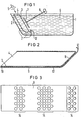
- Figur 1 die schematische Darstellung einer Abscheidungszelle im Schnitt,
- Figur 2 ein Anodenkasten im Schnitt nach der Erfindung,
- Figur 3 eine Aufsicht auf das Kontaktblech beim Anodenkasten nach Fig. 2.
- In Fig. 1 ist die Abscheidungszelle mit 1 bezeichnet. Der linke Wannenrand ist schräg nach oben gezogen und weist auf der Innenseite eine Leitschienenanordnung 2 auf, auf die sich der Anodenkasten 3 abstützt. Der Anodenkasten hat an der oberen Schmalseite eine Einfüllöffnung 4 für Pellets 5 oder anderes geformtes Anodenmaterial und befindet sich bis nahezu an die Einfüllöffnung 4 im Elektrolyten 6. Die Kathode, die auf der Vorderseite des Anodenkastens 3 in einem geringen Abstand angeordnet ist, besteht hier aus dem zu galvanisierenden Werkstück in Form eines plattenförmigen Aufzeichnungsträgers 7, der am vorderen Ende einer stabförmigen und drehbar angeordneten Stromzuführung 8 befestigt ist. Der in Fig. 2 dargestellte Anodenkasten 3 weist auf seiten seiner Auflage auf der Leitschienenanordnung 2 nach Fig. 1 ein Kontaktblech 9 auf, daß im Bereich der Einfüllöffnung 4 am Anodenkasten 3 mittels einer Schweißverbindung 10 befestigt ist. Das Kontaktblech 9, das die Breite des Anodenkastens hat, erstreckt sich über die gesamte Länge des Anodenkastens 3 einschließlich seiner vorderen Schmalseite 11 und endet an seinem freien überstehenden Ende 12 in einer eine Rinne bildenden Krümmung zum Anodenkasten hin. Das so ausgebildet freie Ende 12 erleichtert das Fixieren einer Blende, die für eine gleichmäßige Abscheidung notwendig ist und dient gleichzeitig als Anschlag an der Leitschienenanordnung. Der den Anodenkasten 3 umhüllende Anodensack 13 wird in den von der Unterseite des Anodenkastens und dem Kontaktblech 9 gebildeten Schlitz gezogen.
- Wie die Aufsicht auf das Kontaktblech 9 nach Fig. erkennen läßt, weist das Kontaktblech drei Gruppen von Lochungen 14 auf, die so angeordnet und ausgebildet sind, daß sie einen möglichst guten Durchsatz von Frischelektrolyt durch den Anodenkasten ermöglichen ohne hierdurch die gleichfalls zu fordernden guten elektrisch leitenden Übergänge zwischen der Leitschienenanordnung und dem Kontaktblech bzw. dem Anodenkasten zu beeinträchtigen.
Claims (4)
Priority Applications (1)
| Application Number | Priority Date | Filing Date | Title |
|---|---|---|---|
| AT81101945T ATE4652T1 (de) | 1980-03-18 | 1981-03-16 | Anodenkasten fuer ein galvanisches bad. |
Applications Claiming Priority (2)
| Application Number | Priority Date | Filing Date | Title |
|---|---|---|---|
| DE3010383 | 1980-03-18 | ||
| DE3010383A DE3010383C2 (de) | 1980-03-18 | 1980-03-18 | Anodenkasten für ein galvanisches Bad |
Publications (2)
| Publication Number | Publication Date |
|---|---|
| EP0036204A1 EP0036204A1 (de) | 1981-09-23 |
| EP0036204B1 true EP0036204B1 (de) | 1983-09-14 |
Family
ID=6097569
Family Applications (1)
| Application Number | Title | Priority Date | Filing Date |
|---|---|---|---|
| EP81101945A Expired EP0036204B1 (de) | 1980-03-18 | 1981-03-16 | Anodenkasten für ein galvanisches Bad |
Country Status (5)
| Country | Link |
|---|---|
| US (1) | US4342635A (de) |
| EP (1) | EP0036204B1 (de) |
| JP (1) | JPS5821040B2 (de) |
| AT (1) | ATE4652T1 (de) |
| DE (1) | DE3010383C2 (de) |
Families Citing this family (7)
| Publication number | Priority date | Publication date | Assignee | Title |
|---|---|---|---|---|
| US6132849A (en) * | 1990-10-30 | 2000-10-17 | Minnesota Mining And Manufacturing Company | Receptive media for permanent imaging and methods of preparing and using same |
| US5443727A (en) * | 1990-10-30 | 1995-08-22 | Minnesota Mining And Manufacturing Company | Articles having a polymeric shell and method for preparing same |
| US5318683A (en) * | 1993-02-01 | 1994-06-07 | Quad/Tech, Inc. | Electrodeposition system |
| US5494197A (en) * | 1994-07-27 | 1996-02-27 | Saranac Tank, Inc. | Material handling device for electroplating applications |
| US5904827A (en) * | 1996-10-15 | 1999-05-18 | Reynolds Tech Fabricators, Inc. | Plating cell with rotary wiper and megasonic transducer |
| US6190530B1 (en) * | 1999-04-12 | 2001-02-20 | International Business Machines Corporation | Anode container, electroplating system, method and plated object |
| US6852209B2 (en) * | 2002-10-02 | 2005-02-08 | Applied Materials, Inc. | Insoluble electrode for electrochemical operations on substrates |
Family Cites Families (10)
| Publication number | Priority date | Publication date | Assignee | Title |
|---|---|---|---|---|
| US969921A (en) * | 1909-11-22 | 1910-09-13 | William Thum | Electrolytic apparatus. |
| US2250937A (en) * | 1937-04-16 | 1941-07-29 | American Metal Co Ltd | Electrolytic cell |
| GB984535A (en) * | 1961-11-14 | 1965-02-24 | John Preston & Company Ltd | Improvements in or relating to plating anodes |
| US3223611A (en) * | 1962-01-31 | 1965-12-14 | W W Wells Ltd | Anode basket with dangler for electrolytic plating |
| US3186932A (en) * | 1962-12-10 | 1965-06-01 | Audio Matrix Inc | Apparatus for forming phonograph record masters, mothers, and stampers |
| FR1503553A (fr) | 1966-05-25 | 1967-12-01 | Pathe Marconi Ind Music | Cuve de travail pour la reproduction galvanique de surfaces métalliques, notamment pour l'industrie du disque phonographique |
| DE2336849A1 (de) * | 1973-07-19 | 1975-04-10 | Siemens Ag | Stromzufuehrung fuer anodenmaterial |
| GB1423488A (en) * | 1974-05-10 | 1976-02-04 | Europa Film Ab | Container for anode material in apparatus for electrolytic surface deposition |
| US4187154A (en) * | 1976-09-10 | 1980-02-05 | Fabrication Belge de Disques "Fabeldis" | Method for manufacturing substantially flat dies |
| EP0020008B2 (de) * | 1979-06-01 | 1987-04-15 | EMI Limited | Verfahren zur galvanischen Abscheidung mit grosser Geschwindigkeit und nach diesem Verfahren hergestellte Schallplattenpressform |
-
1980
- 1980-03-18 DE DE3010383A patent/DE3010383C2/de not_active Expired
-
1981
- 1981-02-25 US US06/238,139 patent/US4342635A/en not_active Expired - Fee Related
- 1981-03-16 EP EP81101945A patent/EP0036204B1/de not_active Expired
- 1981-03-16 AT AT81101945T patent/ATE4652T1/de not_active IP Right Cessation
- 1981-03-18 JP JP56038059A patent/JPS5821040B2/ja not_active Expired
Also Published As
| Publication number | Publication date |
|---|---|
| JPS56142898A (en) | 1981-11-07 |
| ATE4652T1 (de) | 1983-09-15 |
| DE3010383A1 (de) | 1981-09-24 |
| JPS5821040B2 (ja) | 1983-04-26 |
| US4342635A (en) | 1982-08-03 |
| DE3010383C2 (de) | 1986-11-06 |
| EP0036204A1 (de) | 1981-09-23 |
Similar Documents
| Publication | Publication Date | Title |
|---|---|---|
| DE2341483C3 (de) | Luftdepolarisationszelle | |
| DE3610951C2 (de) | ||
| DE2433415A1 (de) | Fluglochanordnung fuer bienenkaesten | |
| DE102009049905A1 (de) | Halteeinrichtung für dünne flächige Substrate | |
| EP0036204A1 (de) | Anodenkasten für ein galvanisches Bad | |
| DE4106733C2 (de) | ||
| DE653448C (de) | Elektrolytische AEtzeinrichtung fuer flache Metallplatten, insbesondere Druckplatten | |
| DE2629672C2 (de) | ||
| DE69818779T2 (de) | Elektroplattierungsanlage | |
| DE3229545A1 (de) | Tiefdruckzylinderapparatur zum plattieren und deplattieren | |
| DE2317150A1 (de) | Formierbehaelter fuer batterieplatten | |
| DE4037763A1 (de) | Hochfrequenzdichte baugruppe fuer geraete der elektrischen nachrichtentechnik | |
| DE652197C (de) | Montageplatte aus Isoliermaterial | |
| DE2737034C2 (de) | Anschluß- und Haltevorrichtung für einen plattenförmigen piezoelektrischen Resonator | |
| DE3106305C2 (de) | Messerkonstruktion für eine Doppelhub-Offenfach-Jacquardmaschine | |
| DE1565371B1 (de) | Abschirmung fuer Funkenerosionsmaschinen | |
| DE2032405A1 (de) | Steckbaugruppe für die Hochfrequenz- und Nachrichtentechnik mit Aufnahme | |
| EP0038578B1 (de) | Steckbarer Modul für Hochfrequenzgeräte | |
| DE2119916C3 (de) | Steckeinrichtung | |
| DE1698187A1 (de) | Geraet fuer elektrochemische Analysen | |
| DE2359452C3 (de) | Gehäuse für elektrische und/oder elektronische Bau-Elemente | |
| DE2646711A1 (de) | Verfahren zum ausrichten und fixieren eines elektrodensatzes fuer elektrische akkumulatoren und vorrichtung zu seiner durchfuehrung | |
| AT108433B (de) | Anoden-Stromsammelbatterie. | |
| DE2329581C3 (de) | Schaltungsanordnung zur Einstellung vorbestimmter, fester Dämpfungswerte mit steckbaren Dämpfungsgliedern für Leiterpaare von Fernsprechstromkreisen | |
| DE4416381C2 (de) | Anordnung zur Führung und Befestigung von Ableitungsdrähten in elektrischen Transformatoren oder Drosselspulen |
Legal Events
| Date | Code | Title | Description |
|---|---|---|---|
| PUAI | Public reference made under article 153(3) epc to a published international application that has entered the european phase |
Free format text: ORIGINAL CODE: 0009012 |
|
| AK | Designated contracting states |
Designated state(s): AT BE CH FR GB IT LU NL SE |
|
| RBV | Designated contracting states (corrected) |
Designated state(s): AT BE CH FR GB IT LI LU NL SE |
|
| 17P | Request for examination filed |
Effective date: 19811030 |
|
| ITF | It: translation for a ep patent filed | ||
| GRAA | (expected) grant |
Free format text: ORIGINAL CODE: 0009210 |
|
| AK | Designated contracting states |
Designated state(s): AT BE CH FR GB IT LI LU NL SE |
|
| REF | Corresponds to: |
Ref document number: 4652 Country of ref document: AT Date of ref document: 19830915 Kind code of ref document: T |
|
| ET | Fr: translation filed | ||
| PG25 | Lapsed in a contracting state [announced via postgrant information from national office to epo] |
Ref country code: LU Free format text: LAPSE BECAUSE OF NON-PAYMENT OF DUE FEES Effective date: 19840331 |
|
| PGFP | Annual fee paid to national office [announced via postgrant information from national office to epo] |
Ref country code: BE Payment date: 19840331 Year of fee payment: 4 |
|
| PLBE | No opposition filed within time limit |
Free format text: ORIGINAL CODE: 0009261 |
|
| STAA | Information on the status of an ep patent application or granted ep patent |
Free format text: STATUS: NO OPPOSITION FILED WITHIN TIME LIMIT |
|
| 26N | No opposition filed | ||
| PGFP | Annual fee paid to national office [announced via postgrant information from national office to epo] |
Ref country code: LU Payment date: 19860411 Year of fee payment: 6 |
|
| PGFP | Annual fee paid to national office [announced via postgrant information from national office to epo] |
Ref country code: NL Payment date: 19870331 Year of fee payment: 7 |
|
| PG25 | Lapsed in a contracting state [announced via postgrant information from national office to epo] |
Ref country code: BE Effective date: 19890331 |
|
| BERE | Be: lapsed |
Owner name: POLYGRAM G.M.B.H. Effective date: 19890331 |
|
| PG25 | Lapsed in a contracting state [announced via postgrant information from national office to epo] |
Ref country code: NL Effective date: 19891001 |
|
| NLV4 | Nl: lapsed or anulled due to non-payment of the annual fee | ||
| PGFP | Annual fee paid to national office [announced via postgrant information from national office to epo] |
Ref country code: GB Payment date: 19900228 Year of fee payment: 10 |
|
| PGFP | Annual fee paid to national office [announced via postgrant information from national office to epo] |
Ref country code: FR Payment date: 19900320 Year of fee payment: 10 Ref country code: AT Payment date: 19900320 Year of fee payment: 10 |
|
| PGFP | Annual fee paid to national office [announced via postgrant information from national office to epo] |
Ref country code: SE Payment date: 19900327 Year of fee payment: 10 |
|
| ITTA | It: last paid annual fee | ||
| PGFP | Annual fee paid to national office [announced via postgrant information from national office to epo] |
Ref country code: CH Payment date: 19900627 Year of fee payment: 10 |
|
| PG25 | Lapsed in a contracting state [announced via postgrant information from national office to epo] |
Ref country code: GB Effective date: 19910316 Ref country code: AT Effective date: 19910316 |
|
| PG25 | Lapsed in a contracting state [announced via postgrant information from national office to epo] |
Ref country code: SE Effective date: 19910317 |
|
| PG25 | Lapsed in a contracting state [announced via postgrant information from national office to epo] |
Ref country code: LI Effective date: 19910331 Ref country code: CH Effective date: 19910331 |
|
| GBPC | Gb: european patent ceased through non-payment of renewal fee | ||
| PG25 | Lapsed in a contracting state [announced via postgrant information from national office to epo] |
Ref country code: FR Effective date: 19911129 |
|
| REG | Reference to a national code |
Ref country code: CH Ref legal event code: PL |
|
| REG | Reference to a national code |
Ref country code: FR Ref legal event code: ST |
|
| EUG | Se: european patent has lapsed |
Ref document number: 81101945.4 Effective date: 19911009 |