EP0020008B2 - Verfahren zur galvanischen Abscheidung mit grosser Geschwindigkeit und nach diesem Verfahren hergestellte Schallplattenpressform - Google Patents
Verfahren zur galvanischen Abscheidung mit grosser Geschwindigkeit und nach diesem Verfahren hergestellte Schallplattenpressform Download PDFInfo
- Publication number
- EP0020008B2 EP0020008B2 EP80301255A EP80301255A EP0020008B2 EP 0020008 B2 EP0020008 B2 EP 0020008B2 EP 80301255 A EP80301255 A EP 80301255A EP 80301255 A EP80301255 A EP 80301255A EP 0020008 B2 EP0020008 B2 EP 0020008B2
- Authority
- EP
- European Patent Office
- Prior art keywords
- anode
- cathode
- electrolyte
- arrangement
- tube
- Prior art date
- Legal status (The legal status is an assumption and is not a legal conclusion. Google has not performed a legal analysis and makes no representation as to the accuracy of the status listed.)
- Expired
Links
- 238000007747 plating Methods 0.000 title claims description 13
- 239000003792 electrolyte Substances 0.000 claims description 28
- 238000009713 electroplating Methods 0.000 claims description 10
- PXHVJJICTQNCMI-UHFFFAOYSA-N Nickel Chemical compound [Ni] PXHVJJICTQNCMI-UHFFFAOYSA-N 0.000 description 12
- 239000010405 anode material Substances 0.000 description 8
- 229910052759 nickel Inorganic materials 0.000 description 6
- 230000015572 biosynthetic process Effects 0.000 description 5
- 238000000465 moulding Methods 0.000 description 5
- 239000002245 particle Substances 0.000 description 5
- 239000012535 impurity Substances 0.000 description 3
- KGBXLFKZBHKPEV-UHFFFAOYSA-N boric acid Chemical compound OB(O)O KGBXLFKZBHKPEV-UHFFFAOYSA-N 0.000 description 2
- 239000004327 boric acid Substances 0.000 description 2
- 238000010276 construction Methods 0.000 description 2
- 238000001914 filtration Methods 0.000 description 2
- 238000004519 manufacturing process Methods 0.000 description 2
- 239000000463 material Substances 0.000 description 2
- 238000000034 method Methods 0.000 description 2
- KERTUBUCQCSNJU-UHFFFAOYSA-L nickel(2+);disulfamate Chemical compound [Ni+2].NS([O-])(=O)=O.NS([O-])(=O)=O KERTUBUCQCSNJU-UHFFFAOYSA-L 0.000 description 2
- 239000004033 plastic Substances 0.000 description 2
- 229920003023 plastic Polymers 0.000 description 2
- RYGMFSIKBFXOCR-UHFFFAOYSA-N Copper Chemical compound [Cu] RYGMFSIKBFXOCR-UHFFFAOYSA-N 0.000 description 1
- 229910021586 Nickel(II) chloride Inorganic materials 0.000 description 1
- 239000004743 Polypropylene Substances 0.000 description 1
- 229920004933 Terylene® Polymers 0.000 description 1
- RTAQQCXQSZGOHL-UHFFFAOYSA-N Titanium Chemical compound [Ti] RTAQQCXQSZGOHL-UHFFFAOYSA-N 0.000 description 1
- 239000010949 copper Substances 0.000 description 1
- 229910052802 copper Inorganic materials 0.000 description 1
- 150000002815 nickel Chemical class 0.000 description 1
- QMMRZOWCJAIUJA-UHFFFAOYSA-L nickel dichloride Chemical compound Cl[Ni]Cl QMMRZOWCJAIUJA-UHFFFAOYSA-L 0.000 description 1
- 239000005020 polyethylene terephthalate Substances 0.000 description 1
- -1 polypropylene Polymers 0.000 description 1
- 229920001155 polypropylene Polymers 0.000 description 1
- 238000005086 pumping Methods 0.000 description 1
- 239000010936 titanium Substances 0.000 description 1
- 229910052719 titanium Inorganic materials 0.000 description 1
Images
Classifications
-
- C—CHEMISTRY; METALLURGY
- C25—ELECTROLYTIC OR ELECTROPHORETIC PROCESSES; APPARATUS THEREFOR
- C25D—PROCESSES FOR THE ELECTROLYTIC OR ELECTROPHORETIC PRODUCTION OF COATINGS; ELECTROFORMING; APPARATUS THEREFOR
- C25D5/00—Electroplating characterised by the process; Pretreatment or after-treatment of workpieces
- C25D5/08—Electroplating with moving electrolyte e.g. jet electroplating
-
- C—CHEMISTRY; METALLURGY
- C25—ELECTROLYTIC OR ELECTROPHORETIC PROCESSES; APPARATUS THEREFOR
- C25D—PROCESSES FOR THE ELECTROLYTIC OR ELECTROPHORETIC PRODUCTION OF COATINGS; ELECTROFORMING; APPARATUS THEREFOR
- C25D1/00—Electroforming
- C25D1/10—Moulds; Masks; Masterforms
-
- C—CHEMISTRY; METALLURGY
- C25—ELECTROLYTIC OR ELECTROPHORETIC PROCESSES; APPARATUS THEREFOR
- C25D—PROCESSES FOR THE ELECTROLYTIC OR ELECTROPHORETIC PRODUCTION OF COATINGS; ELECTROFORMING; APPARATUS THEREFOR
- C25D5/00—Electroplating characterised by the process; Pretreatment or after-treatment of workpieces
- C25D5/60—Electroplating characterised by the structure or texture of the layers
- C25D5/605—Surface topography of the layers, e.g. rough, dendritic or nodular layers
- C25D5/611—Smooth layers
Definitions
- This invention relates to electroplating and especially, although not exclusively, to the formation of stamper plates for moulding disc records.
- Stamper plates for disc records are commonly made of nickel and are formed by an electroplating process in which a rotating disc cathode is suspended in a tank of electrolyte opposite a basket, typically of a mesh or cage construction, holding nickel anode material.
- the anode material is comprised of loose nickel spheres or cubes, and in order to maintain a constant anode profile opposite the cathode the basket may be inclined to the horizontal. In this position the surface of the basket closest to the cathode defines the profile of the anode surface.
- electrolyte is passed through the basket towards the cathode, or alternatively across the surface of the anode, so that in the region between the electrodes the electrolyte is continually replenished.
- an object of the present invention to provide an improved form of electroplating arrangement in which substantially nodule free plates may be formed even at relatively high current densities.
- the invention provides an electroplating arrangement comprising a container for an electrolyte, an anode and a cathode having a disc-shaped plating surface characterised in that a generally annular tube is supplied, in use, with electrolyte and a plurality of inwardly facing holes is provided in the tube to admit electrolyte, so supplied, into a region between the anode and cathode encompassed by the tube to establish a flow of electrolyte in a direction away from the cathode towards the anode, the holes (10) being arranged circumferentiallyto surround said region.
- the tube may enclose substantially the whole of the region between the cathode and anode.
- the anode may comprise anode material contained within an anode basket and both the basket and the cathode surface may be inclined to the horizontal.
- the angle of inclination of the anode basket and the cathode surface may lie between 30° and 60° and is preferably 45°.
- the anode material may be nickel and the electrolyte may comprise a solution of a major proportion of a nickel salt such as nickel sulphamate and a minor proportion of boric acid.
- an electroplating arrangement as described above wherein said plating surface of the cathode is a stamper plate.
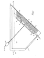
- Figure 1 of the drawings is suitable for the formation of stamper plates of the type used for moulding disc records.
- a negative impression of a recording may be formed on the stamper plate which is then used to create a positive impression by moulding plastics material to form the disc record.
- a cathode, 1 has a disc shaped plating surface 2, and is suspended in a tank, 3, containing an electrolyte, 4, opposite a source of an anode material, 5, contained within an anode basket, 6.
- the basket is typically made of titanium and has an open mesh construction which permits a flow of electrolyte through the anode material which is conveniently in the form of loose spheres or cubes.
- a flow of electrolyte is established in a direction away from the cathode towards the anode so that impurity particles released at the anode, and which are thought to be responsible for the formation of nodules, are substantially prevented from reaching the plating area.
- this object is achieved by causing a positive flow towards the anode using a substantially circular tube, 7, preferably of a plastics material e.g. polypropylene or PVC, which encloses the region between the electrodes.
- a substantially circular tube 7, preferably of a plastics material e.g. polypropylene or PVC, which encloses the region between the electrodes.
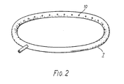
- This tube is shown in perspective view in Figure 2 of the drawings.
- Filtered electrolyte is supplied to the tube, 7, via a detachable feed pipe, 8, and is admitted to the interelectrode region, 9, through a plurality of inwardly facing holes, 10, disposed around the internal circumference of the tube.
- the tube has a cross-sectional diameter of 2 cm, and forms a circular ring having an outside diameter of between 35 and 40 cm.
- the holes, 10, have a diameter of 3 mm and are spaced at 5 cm intervals.
- the holes may typically have a diameter of between 2 and 5 mm.
- the tube, 7, encloses the whole of the region between the anode and cathode, it is only necessary for a region of relatively high pressure to be developed in the electrolyte close to the cathode.
- the circular tube, 7, may be positioned adjacent to the cathode surface but spaced away from the anode.
- both the cathode and the anode basket are inclined to the horizontal, at an angle of about 45°, so that a uniform profile of the anode material, defined by the upper surface of the basket, may be maintained opposite the cathode plating surface.
- the inclined arrangement illustrated in the drawing is to be preferred, the present invention can also be applied to an arrangement in which the anode basket and the cathode surface assume horizontal positions.
- a drive means 13 to rotate the cathode about an axis perpendicular to the plane of the plating surface, typically at a speed of about 200 r.p.m.
- Electrical connections to the basket and drive means are made, as shown in Figure 1, and these are arranged to provide a difference in electrical potential between the anode and cathode.
- contact with the drive means may be achieved by means of electrical contact brushes.
- the stamper plates are made of nickel (although copper is sometimes used) and in the present example the anode material comprises loose nickel spheres and the electrolyte is prepared from a solution of a major proportion of nickel sulphamate (typically 600 gm/I) and minor proportions of nickel chloride (typically 10-15 gm/I) and boric acid (typically 40 gm/I).
- nickel sulphamate typically 600 gm/I
- nickel chloride typically 10-15 gm/I
- boric acid typically 40 gm/I
- the present invention is clearly applicable to the formation of stamper plates for disc records, or video discs (for which the quality of the moulding surface is particularly important) it will be appreciated that the present invention may be used in other applications in which a high quality electroplated surface is desired.
Landscapes
- Chemical & Material Sciences (AREA)
- Engineering & Computer Science (AREA)
- Chemical Kinetics & Catalysis (AREA)
- Electrochemistry (AREA)
- Materials Engineering (AREA)
- Metallurgy (AREA)
- Organic Chemistry (AREA)
- Electroplating Methods And Accessories (AREA)
- Manufacturing Optical Record Carriers (AREA)
- Casting Or Compression Moulding Of Plastics Or The Like (AREA)
- Shaping Of Tube Ends By Bending Or Straightening (AREA)
Claims (4)
Applications Claiming Priority (2)
| Application Number | Priority Date | Filing Date | Title |
|---|---|---|---|
| GB7919209 | 1979-06-01 | ||
| GB7919209 | 1979-06-01 |
Publications (3)
| Publication Number | Publication Date |
|---|---|
| EP0020008A1 EP0020008A1 (de) | 1980-12-10 |
| EP0020008B1 EP0020008B1 (de) | 1984-05-23 |
| EP0020008B2 true EP0020008B2 (de) | 1987-04-15 |
Family
ID=10505585
Family Applications (1)
| Application Number | Title | Priority Date | Filing Date |
|---|---|---|---|
| EP80301255A Expired EP0020008B2 (de) | 1979-06-01 | 1980-04-18 | Verfahren zur galvanischen Abscheidung mit grosser Geschwindigkeit und nach diesem Verfahren hergestellte Schallplattenpressform |
Country Status (4)
| Country | Link |
|---|---|
| US (1) | US4269669A (de) |
| EP (1) | EP0020008B2 (de) |
| JP (1) | JPS569396A (de) |
| DE (1) | DE3067925D1 (de) |
Families Citing this family (21)
| Publication number | Priority date | Publication date | Assignee | Title |
|---|---|---|---|---|
| DE3010383C2 (de) * | 1980-03-18 | 1986-11-06 | Polygram Gmbh, 2000 Hamburg | Anodenkasten für ein galvanisches Bad |
| NL8005427A (nl) * | 1980-09-30 | 1982-04-16 | Veco Beheer Bv | Werkwijze voor het vervaardigen van zeefmateriaal, verkregen zeefmateriaal alsmede inrichting voor het uitvoeren van de werkwijze. |
| SE8101046L (sv) * | 1981-02-16 | 1982-08-17 | Europafilm | Anordning vid anleggningar, serskilt for matrisering av grammofonskivor och dylikt |
| DE3114106A1 (de) * | 1981-04-08 | 1982-10-28 | Teldec Telefunken-Decca-Schallplatten Gmbh, 2000 Hamburg | Verfahren zur galvanischen abscheidung von kupfer auf einem substrat |
| FR2510615A1 (fr) * | 1981-07-31 | 1983-02-04 | Exnii Metallorezh Stankov | Procede de fabrication d'outils formants metalliques par galvanoplastie et outils formants obtenus par ledit procede |
| EP0076569B1 (de) | 1981-10-01 | 1986-08-27 | EMI Limited | Elektroplattierungsvorrichtung |
| US4415423A (en) * | 1982-09-09 | 1983-11-15 | Rca Corporation | Electroforming apparatus for use in matrixing of record molding parts |
| US4687554A (en) * | 1986-02-03 | 1987-08-18 | Omi International Corporation | Electrolytic apparatus and process |
| DE3889187T2 (de) * | 1987-10-01 | 1994-11-24 | Furukawa Circuit Foil | Unlösliche Elektrode. |
| SE467976B (sv) * | 1991-02-20 | 1992-10-12 | Dcm Innovation Ab | Anordning foer elektroplaetering, vid framstaellning av matriser foer tillverkning av t ex cd-skivor samt foerfarande foer tillverkning av matriser medelst anordningen |
| US5597460A (en) * | 1995-11-13 | 1997-01-28 | Reynolds Tech Fabricators, Inc. | Plating cell having laminar flow sparger |
| DE59602798D1 (de) * | 1996-04-01 | 1999-09-23 | Sonopress Prod | Galvanische Abscheidungszelle mit Leitblende |
| US5904827A (en) * | 1996-10-15 | 1999-05-18 | Reynolds Tech Fabricators, Inc. | Plating cell with rotary wiper and megasonic transducer |
| US5683564A (en) * | 1996-10-15 | 1997-11-04 | Reynolds Tech Fabricators Inc. | Plating cell and plating method with fluid wiper |
| DE29701092U1 (de) * | 1997-01-23 | 1997-03-20 | Technotrans GmbH, 48336 Sassenberg | Galvanische Abscheidungsvorrichtung |
| US6217727B1 (en) * | 1999-08-30 | 2001-04-17 | Micron Technology, Inc. | Electroplating apparatus and method |
| JP2002004076A (ja) * | 2000-06-16 | 2002-01-09 | Sony Corp | 電鋳装置 |
| US20040055873A1 (en) * | 2002-09-24 | 2004-03-25 | Digital Matrix Corporation | Apparatus and method for improved electroforming |
| ITTO20070704A1 (it) * | 2007-10-05 | 2009-04-06 | Create New Technology S R L | Sistema e metodo di placcatura di leghe metalliche mediante tecnologia galvanica |
| US10190232B2 (en) | 2013-08-06 | 2019-01-29 | Lam Research Corporation | Apparatuses and methods for maintaining pH in nickel electroplating baths |
| US9732434B2 (en) | 2014-04-18 | 2017-08-15 | Lam Research Corporation | Methods and apparatuses for electroplating nickel using sulfur-free nickel anodes |
Family Cites Families (13)
| Publication number | Priority date | Publication date | Assignee | Title |
|---|---|---|---|---|
| CA544340A (en) * | 1957-07-30 | N.V. Philips Gloeilampenfabrieken | Method of electro-forming moulds for sound-carriers | |
| US1019969A (en) * | 1910-02-19 | 1912-03-12 | Fernand Lacroix | Electrolysis of metallic solutions. |
| US2675348A (en) * | 1950-09-16 | 1954-04-13 | Greenspan Lawrence | Apparatus for metal plating |
| US3186932A (en) * | 1962-12-10 | 1965-06-01 | Audio Matrix Inc | Apparatus for forming phonograph record masters, mothers, and stampers |
| FR1503553A (fr) * | 1966-05-25 | 1967-12-01 | Pathe Marconi Ind Music | Cuve de travail pour la reproduction galvanique de surfaces métalliques, notamment pour l'industrie du disque phonographique |
| US3558455A (en) * | 1968-03-04 | 1971-01-26 | Kennecott Copper Corp | Electrolyte-circulating,electrolytic cell |
| JPS49123131A (de) * | 1973-03-31 | 1974-11-25 | ||
| GB1423488A (en) * | 1974-05-10 | 1976-02-04 | Europa Film Ab | Container for anode material in apparatus for electrolytic surface deposition |
| JPS5144568A (ja) * | 1974-10-16 | 1976-04-16 | Nippon Telegraph & Telephone | Denkaikaseiso |
| JPS5243733A (en) * | 1975-10-03 | 1977-04-06 | Nippon Kokan Kk | Method of forming jet stream of plating solution in horizontal type electroplating and apparatus for said method |
| US4062755A (en) * | 1976-05-03 | 1977-12-13 | Bell Telephone Laboratories, Incorporated | Electroplating anode plenum |
| JPS5334633A (en) * | 1976-09-14 | 1978-03-31 | Toppan Printing Co Ltd | High speed electrocasting device |
| JPS53119227A (en) * | 1977-03-28 | 1978-10-18 | Sankuesuto Kk | Plating method |
-
1980
- 1980-04-18 EP EP80301255A patent/EP0020008B2/de not_active Expired
- 1980-04-18 DE DE8080301255T patent/DE3067925D1/de not_active Expired
- 1980-04-23 US US06/143,118 patent/US4269669A/en not_active Expired - Lifetime
- 1980-05-22 JP JP6839480A patent/JPS569396A/ja active Pending
Also Published As
| Publication number | Publication date |
|---|---|
| JPS569396A (en) | 1981-01-30 |
| DE3067925D1 (en) | 1984-06-28 |
| EP0020008A1 (de) | 1980-12-10 |
| US4269669A (en) | 1981-05-26 |
| EP0020008B1 (de) | 1984-05-23 |
Similar Documents
| Publication | Publication Date | Title |
|---|---|---|
| EP0020008B2 (de) | Verfahren zur galvanischen Abscheidung mit grosser Geschwindigkeit und nach diesem Verfahren hergestellte Schallplattenpressform | |
| EP0076569B1 (de) | Elektroplattierungsvorrichtung | |
| US5597460A (en) | Plating cell having laminar flow sparger | |
| US5421987A (en) | Precision high rate electroplating cell and method | |
| US8313631B2 (en) | Apparatus and methods for electrochemical processing of microfeature wafers | |
| US4359375A (en) | Anode assembly for electroforming record matrixes | |
| US3785938A (en) | Method for making abrasive articles | |
| JPH0474882A (ja) | 電鋳装置 | |
| EP0049022A1 (de) | Verfahren zum Herstellen von perforiertem Material sowie nach dem Verfahren hergestelltes Material | |
| US3186932A (en) | Apparatus for forming phonograph record masters, mothers, and stampers | |
| US3767537A (en) | Method and apparatus for continuous production of nickel foil | |
| US4539079A (en) | Method and apparatus for electroforming a stamper for producing a high-density information recording carrier | |
| US3929592A (en) | Plating apparatus and method for rotary engine housings | |
| US2583101A (en) | Electrolytic cell | |
| US3619401A (en) | Apparatus for electrodeposition | |
| JPH0349998B2 (de) | ||
| US3634047A (en) | Electroplated member and method and apparatus for electroplating | |
| US4720329A (en) | Apparatus and method for the electrolytic plating of layers onto computer memory hard discs | |
| US2905613A (en) | Methods and apparatus for the electrolytic-refining of titanium metal or zirconium metal | |
| US2181490A (en) | Electroplating apparatus | |
| TWI410532B (zh) | 晶圓填孔垂直式電極電鍍設備 | |
| US1744792A (en) | Electroplating apparatus | |
| CN2695454Y (zh) | 改进电铸工艺中沉积均匀性的装置 | |
| GB1582590A (en) | Electrodeposition | |
| US3619389A (en) | Electrodeposition system |
Legal Events
| Date | Code | Title | Description |
|---|---|---|---|
| PUAI | Public reference made under article 153(3) epc to a published international application that has entered the european phase |
Free format text: ORIGINAL CODE: 0009012 |
|
| AK | Designated contracting states |
Designated state(s): DE FR GB IT NL SE |
|
| 17P | Request for examination filed |
Effective date: 19810220 |
|
| ITF | It: translation for a ep patent filed | ||
| GRAA | (expected) grant |
Free format text: ORIGINAL CODE: 0009210 |
|
| AK | Designated contracting states |
Designated state(s): DE FR GB IT NL SE |
|
| REF | Corresponds to: |
Ref document number: 3067925 Country of ref document: DE Date of ref document: 19840628 |
|
| ET | Fr: translation filed | ||
| PLBI | Opposition filed |
Free format text: ORIGINAL CODE: 0009260 |
|
| REG | Reference to a national code |
Ref country code: GB Ref legal event code: 746 |
|
| 26 | Opposition filed |
Opponent name: N.V. PHILIPS' GLOEILAMPENFABRIEKEN Effective date: 19850209 |
|
| REG | Reference to a national code |
Ref country code: FR Ref legal event code: DL |
|
| NLR1 | Nl: opposition has been filed with the epo |
Opponent name: N.V.PHILIPS' GLOEILAMPENFABRIEKEN |
|
| ITF | It: translation for a ep patent filed | ||
| PUAH | Patent maintained in amended form |
Free format text: ORIGINAL CODE: 0009272 |
|
| STAA | Information on the status of an ep patent application or granted ep patent |
Free format text: STATUS: PATENT MAINTAINED AS AMENDED |
|
| 27A | Patent maintained in amended form |
Effective date: 19870415 |
|
| AK | Designated contracting states |
Kind code of ref document: B2 Designated state(s): DE FR GB IT NL SE |
|
| ET3 | Fr: translation filed ** decision concerning opposition | ||
| NLR2 | Nl: decision of opposition | ||
| NLR3 | Nl: receipt of modified translations in the netherlands language after an opposition procedure | ||
| PGFP | Annual fee paid to national office [announced via postgrant information from national office to epo] |
Ref country code: SE Payment date: 19890307 Year of fee payment: 10 |
|
| PGFP | Annual fee paid to national office [announced via postgrant information from national office to epo] |
Ref country code: FR Payment date: 19890323 Year of fee payment: 10 |
|
| PGFP | Annual fee paid to national office [announced via postgrant information from national office to epo] |
Ref country code: GB Payment date: 19890331 Year of fee payment: 10 |
|
| ITTA | It: last paid annual fee | ||
| PGFP | Annual fee paid to national office [announced via postgrant information from national office to epo] |
Ref country code: NL Payment date: 19890430 Year of fee payment: 10 |
|
| PGFP | Annual fee paid to national office [announced via postgrant information from national office to epo] |
Ref country code: DE Payment date: 19890616 Year of fee payment: 10 |
|
| PG25 | Lapsed in a contracting state [announced via postgrant information from national office to epo] |
Ref country code: GB Effective date: 19900418 |
|
| PG25 | Lapsed in a contracting state [announced via postgrant information from national office to epo] |
Ref country code: SE Effective date: 19900419 |
|
| REG | Reference to a national code |
Ref country code: GB Ref legal event code: 732 |
|
| PG25 | Lapsed in a contracting state [announced via postgrant information from national office to epo] |
Ref country code: NL Effective date: 19901101 |
|
| REG | Reference to a national code |
Ref country code: FR Ref legal event code: TP |
|
| GBPC | Gb: european patent ceased through non-payment of renewal fee | ||
| NLV4 | Nl: lapsed or anulled due to non-payment of the annual fee | ||
| PG25 | Lapsed in a contracting state [announced via postgrant information from national office to epo] |
Ref country code: FR Effective date: 19901228 |
|
| PG25 | Lapsed in a contracting state [announced via postgrant information from national office to epo] |
Ref country code: DE Effective date: 19910101 |
|
| REG | Reference to a national code |
Ref country code: FR Ref legal event code: ST |
|
| EUG | Se: european patent has lapsed |
Ref document number: 80301255.8 Effective date: 19910110 |