EP0036112B1 - Imprimante par frappe - Google Patents
Imprimante par frappe Download PDFInfo
- Publication number
- EP0036112B1 EP0036112B1 EP81101366A EP81101366A EP0036112B1 EP 0036112 B1 EP0036112 B1 EP 0036112B1 EP 81101366 A EP81101366 A EP 81101366A EP 81101366 A EP81101366 A EP 81101366A EP 0036112 B1 EP0036112 B1 EP 0036112B1
- Authority
- EP
- European Patent Office
- Prior art keywords
- character
- record carrier
- characters
- line
- Prior art date
- Legal status (The legal status is an assumption and is not a legal conclusion. Google has not performed a legal analysis and makes no representation as to the accuracy of the status listed.)
- Expired
Links
Images
Classifications
-
- B—PERFORMING OPERATIONS; TRANSPORTING
- B41—PRINTING; LINING MACHINES; TYPEWRITERS; STAMPS
- B41J—TYPEWRITERS; SELECTIVE PRINTING MECHANISMS, i.e. MECHANISMS PRINTING OTHERWISE THAN FROM A FORME; CORRECTION OF TYPOGRAPHICAL ERRORS
- B41J2/00—Typewriters or selective printing mechanisms characterised by the printing or marking process for which they are designed
- B41J2/485—Typewriters or selective printing mechanisms characterised by the printing or marking process for which they are designed characterised by the process of building-up characters or image elements applicable to two or more kinds of printing or marking processes
- B41J2/50—Typewriters or selective printing mechanisms characterised by the printing or marking process for which they are designed characterised by the process of building-up characters or image elements applicable to two or more kinds of printing or marking processes by the selective combination of two or more non-identical printing elements
-
- B—PERFORMING OPERATIONS; TRANSPORTING
- B41—PRINTING; LINING MACHINES; TYPEWRITERS; STAMPS
- B41J—TYPEWRITERS; SELECTIVE PRINTING MECHANISMS, i.e. MECHANISMS PRINTING OTHERWISE THAN FROM A FORME; CORRECTION OF TYPOGRAPHICAL ERRORS
- B41J9/00—Hammer-impression mechanisms
- B41J9/02—Hammers; Arrangements thereof
- B41J9/10—Hammers; Arrangements thereof of more than one hammer, e.g. one for each character position
Definitions
- the invention relates to a stop printer with a relative movement between the recording medium and the type carrier in the line direction.
- GB-A-786 053 discloses an impact printer which has a rotating drum with type segments, in front of which a recording medium is guided. Adjacent to the other side of the record carrier is a series of print hammers which have the width of a complete character.
- the type segments have a dot shape and are arranged one after the other on the drum in seven columns running perpendicular to the print line, viewed in the circumferential direction. By responding to the pressure hammers for different lengths, starting with a dot shape, strokes of different lengths extending in the gap direction can be generated.
- the drum carries an integer multiple of seven type segments, so that several characters can be printed in parallel.
- the record carrier For the purpose of creating a line, the record carrier must be moved in the line direction with respect to the drum. Two relative movements between the recording medium and the printing drum are thus to be carried out in order to create a character line.
- the invention seeks to remedy this.
- the invention as characterized in the claims, solves the problem of creating an impact printer with a relatively high recording medium throughput and low maintenance.
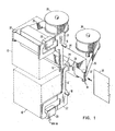
- the recording medium transport path 14 is adjacent to the upper hammer group 10 and the lower hammer group 12.
- the hammer groups 10 and 12 each contain twenty-two print hammers 16 which are arranged at a pitch of 5.08 mm.
- the hammer groups 10 and 12 are mounted so that their pressure hammers 16 are in a row with a pitch of 2.54 mm.
- Each of the pressure hammers 16 can be pivoted about the bearing axis 18, which extends over the entire length within each hammer group 10 or 12.
- An electromagnet 20 is assigned to each printing hammer, when the arm 22 of the assigned printing hammer 16 is excited when it is pivoted about the bearing axis 18 and the other arm of the printing hammer 16 is thereby moved with its stop surface 24 against the recording medium 36.
- the upper and lower hammer groups 10 and 12 are identical and have a structure corresponding to US Pat. No. 3,747,521.
- the ink ribbon 26 is moved from the supply spool 30 to the take-up spool 28.
- the ink ribbon 26 is kept tensioned within the record carrier transport path 14 by the two rollers 32.
- the character segment plate 34 is also mounted adjacent to the recording medium transport path 14, but facing the other side of the ink ribbon 26.
- the recording medium 36 is moved between the ink ribbon 26 and the print hammers 16.
- the printing is carried out by independently hitting the predetermined print hammers 16, as a result of which the stop surfaces 24 press the record carrier 36 and the ink ribbon 26 against a specific character segment 38.
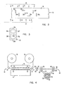
- the character segment plate 34 Details of the character segment plate 34 are shown in FIG. 2.
- the character segments 38 are produced on the plate 34 by conventional methods, such as casting or material-removing methods.
- seven character segments 38a to 38g are used for printing one character.
- the segment matrix 40 is shown in FIG. 3.
- Printing a 3 requires striking segments 38c through 38g, while printing an 8 requires striking all of the character segments.
- Each character position on the character segment plate 34 contains the seven character segments of the segment matrix of FIG. 3 and seven print hammers, four of which one Hammer group and three of the other hammer group are assigned.
- the character segment plate 34 can be made of a relatively inexpensive material in or on which the character segments are relatively easy to manufacture. It is therefore possible to replace a worn character segment plate 34 with a new one.
- the exchange also enables different characters or types of characters to be printed. It is of course also possible to attach the drawing segments to the stop surface 24 of the print hammer 16, although this would increase the maintenance costs.
- FIG. 4 shows the transport of the record carrier 36 and the sensing elements for sensing the speed and the position of the record carrier with respect to a reference point.
- the timing disk 56 is equipped with position indicators equally spaced apart and is placed on the shaft of the motor 46.
- the position sensor 58 is adjacent to the clock disk 56 and transmits a signal when each position indicator passes.
- the light source 60 and the sensor 62 are fastened in the further course of the record carrier transport path 14. When the leading edge 36a of a recording medium reaches the light source 60, it interrupts the light beam, whereby the sensor 62 generates a signal which indicates the passage of the leading edge of a recording medium.
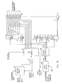
- FIG. 5 shows the basic elements of the control circuit. For the purposes of the description, it is assumed that six characters are to be printed on the record carrier. Thus, using a seven segment character matrix, forty-two print hammers and control guides are necessary.
- a start number to be printed is selected by the operator and printed on the first record carrier, while the following numbers are automatically increased.
- the start numbers are entered into a control processor, not shown, which enters the characters via a character line into a 6-byte register 64, one byte being assigned to one character.
- the contents of register 64 are then shifted under clock control over line 68 into segment decoder 66.
- the decoded segments for the first character are then separately entered into print register 70. Similarly, the decoded segment signals for the next five characters are entered into print registers 72, 74, 76, 78 and 80.
- the control processor then inputs a binary number into position counter 82 which completes the control of the pressure.
- position counter 82 When the leading edge 36a of the record carrier 36 is sensed, the signal generated by the sensor 62 initiates step-by-step subtraction of the position counter 82. Subsequently, the subtraction is continued by the signals of the position transmitter 58, namely by one for each signal received.
- the position counter 82 reaches zero, it generates a continuous pulse until reset, which is combined in the AND circuit 84 with the output signal of the position encoder.
- the output of AND circuit 84 becomes a logic one, the 42 bit sequencer is started.
- the 42-bit sequencer 86 has forty-two output lines on which a logical one appears in the order from the first to the forty-second line under the control of the signal from the position encoder. After the position counter 82 has reached the zero count, the start signal of the position encoder thus excites the first output line of the 42-bit sequential circuit 86, whereupon the subsequent signals of the position encoder excite the successive output lines of the 42-bit sequential circuit 86.
- a separately generated clock pulse is fed to the 42 bit sequencer 86 to control the width of its output pulses. This pulse width control is used to control the hammer pulses.
- the output lines of the 42 bit sequential circuit 86 are combined in AND circuits 88 with character segment bits of the corresponding print register.
- the printing of the first character is controlled, for example, by combining the seven output lines of the first print register 70 with the seven output lines of the 42-bit sequencer 86 in the AND circuits 88a to 88g. the remaining bridge registers 72, 74, 76, 78 and-80 combined with the following groups of seven output lines of the 42 bit sequencer 86.
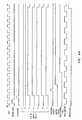
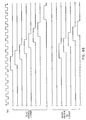
- FIGS. 6A and 6B A timing diagram for the various signals and devices for printing character 3 is shown in Figures 6A and 6B.
- An identical clock pulse 90 is shown in the first line of FIGS. 6A and 6B and serves as a reference for the following control aspects of the printing process.
Landscapes
- Character Spaces And Line Spaces In Printers (AREA)
- Handling Of Sheets (AREA)
Claims (3)
Applications Claiming Priority (2)
| Application Number | Priority Date | Filing Date | Title |
|---|---|---|---|
| US06/131,573 US4326814A (en) | 1980-03-19 | 1980-03-19 | Document printing device having a platen with character segments thereon |
| US131573 | 1980-03-19 |
Publications (2)
| Publication Number | Publication Date |
|---|---|
| EP0036112A1 EP0036112A1 (fr) | 1981-09-23 |
| EP0036112B1 true EP0036112B1 (fr) | 1984-07-11 |
Family
ID=22450046
Family Applications (1)
| Application Number | Title | Priority Date | Filing Date |
|---|---|---|---|
| EP81101366A Expired EP0036112B1 (fr) | 1980-03-19 | 1981-02-25 | Imprimante par frappe |
Country Status (3)
| Country | Link |
|---|---|
| US (1) | US4326814A (fr) |
| EP (1) | EP0036112B1 (fr) |
| DE (1) | DE3164642D1 (fr) |
Families Citing this family (4)
| Publication number | Priority date | Publication date | Assignee | Title |
|---|---|---|---|---|
| US4540296A (en) * | 1981-12-21 | 1985-09-10 | International Business Machines Corporation | Bar band intersectional matrix printer |
| US4592668A (en) * | 1982-09-30 | 1986-06-03 | American Can Co. | Method for stamping indicia on materials |
| US4476781A (en) * | 1982-09-30 | 1984-10-16 | American Can Company | Apparatus for stamping indicia on materials |
| US5699257A (en) * | 1996-05-02 | 1997-12-16 | Micro General Corporation | Postage meter |
Family Cites Families (7)
| Publication number | Priority date | Publication date | Assignee | Title |
|---|---|---|---|---|
| GB537343A (en) * | 1939-12-14 | 1941-06-18 | Kenyon Secretan | Improvements in and relating to monogrammic printing devices |
| US3367469A (en) * | 1963-08-29 | 1968-02-06 | Dole Valve Co | Digital printer with plural similar print heads |
| DE1251058B (de) * | 1963-10-04 | 1967-09-28 | General Precision Ine , Glendale, CaU (V Si A) | Seriendruckwerk |
| DE1801763A1 (de) * | 1968-10-08 | 1970-07-09 | Olympia Buerosysteme Gmbh | Typenraddruckwerk |
| US4082035A (en) * | 1972-11-02 | 1978-04-04 | Svenska Dataregister Ab | High speed printer having segmented drum |
| JPS51127824A (en) * | 1975-04-28 | 1976-11-08 | Dezain Fuoo Asoshieetsu | Printer |
| US4092921A (en) * | 1976-05-27 | 1978-06-06 | Sheldon-Sodeco Printer, Inc. | High speed printer module |
-
1980
- 1980-03-19 US US06/131,573 patent/US4326814A/en not_active Expired - Lifetime
-
1981
- 1981-02-25 DE DE8181101366T patent/DE3164642D1/de not_active Expired
- 1981-02-25 EP EP81101366A patent/EP0036112B1/fr not_active Expired
Also Published As
| Publication number | Publication date |
|---|---|
| DE3164642D1 (en) | 1984-08-16 |
| US4326814A (en) | 1982-04-27 |
| EP0036112A1 (fr) | 1981-09-23 |
Similar Documents
| Publication | Publication Date | Title |
|---|---|---|
| DE2749669C2 (de) | Tintenstrahlschreiber | |
| DE2421658A1 (de) | Materndruckvorrichtung | |
| DE1905226A1 (de) | Druckvorrichtung | |
| DE1264833B (de) | Trommel- oder Ketten-Schnelldrucker | |
| DE2501035A1 (de) | Frankiermaschine mit einer druckfarbe ausstossenden postwertzeichendruckvorrichtung | |
| DE1209783B (de) | Kettendrucker fuer datenverarbeitende Bueromaschinen | |
| CH640778A5 (de) | Einrichtung zur aufzeichnung von druckzeichen auf einem lichtempfindlichen medium. | |
| DE2648838A1 (de) | Schnelldrucker | |
| DE1549777A1 (de) | Druckeinrichtung | |
| DE2840279C2 (de) | Tintenstrahldrucker | |
| DE2400444A1 (de) | Steuerung fuer druckeinrichtungen | |
| DE2711704C3 (de) | Fahrkartendrucker | |
| EP0036112B1 (fr) | Imprimante par frappe | |
| DE1145405B (de) | Kettendrucker fuer datenverarbeitende Maschinen | |
| DE3234415C2 (fr) | ||
| DE3233425C2 (fr) | ||
| DE2519861A1 (de) | Raddrucker | |
| DE2111398A1 (de) | Hochleistungsseriendrucker | |
| DE3546573C2 (fr) | ||
| DE2503112B2 (de) | Parallel-Rasterdrucker | |
| DE1202547B (de) | Anordnung zur Beeinflussung des Druckbildes bei elektronisch gesteuerten Mosaikdruckern | |
| DE3336597C2 (fr) | ||
| DE7030354U (de) | Druckhammerelement fuer datenverarbeitungs-druckwerke. | |
| DE2455831C3 (de) | Druckeinrichtung mit einer rotierenden Typenscheibe | |
| DE2348712C3 (de) | Vorrichtung zum Drucken von aus Zeichenelementen zusammengesetzten Zeichen |
Legal Events
| Date | Code | Title | Description |
|---|---|---|---|
| PUAI | Public reference made under article 153(3) epc to a published international application that has entered the european phase |
Free format text: ORIGINAL CODE: 0009012 |
|
| AK | Designated contracting states |
Designated state(s): DE FR GB IT |
|
| 17P | Request for examination filed |
Effective date: 19811027 |
|
| GRAA | (expected) grant |
Free format text: ORIGINAL CODE: 0009210 |
|
| AK | Designated contracting states |
Designated state(s): DE FR GB IT |
|
| PG25 | Lapsed in a contracting state [announced via postgrant information from national office to epo] |
Ref country code: IT Free format text: LAPSE BECAUSE OF FAILURE TO SUBMIT A TRANSLATION OF THE DESCRIPTION OR TO PAY THE FEE WITHIN THE PRESCRIBED TIME-LIMIT;WARNING: LAPSES OF ITALIAN PATENTS WITH EFFECTIVE DATE BEFORE 2007 MAY HAVE OCCURRED AT ANY TIME BEFORE 2007. THE CORRECT EFFECTIVE DATE MAY BE DIFFERENT FROM THE ONE RECORDED. Effective date: 19840711 |
|
| REF | Corresponds to: |
Ref document number: 3164642 Country of ref document: DE Date of ref document: 19840816 |
|
| ET | Fr: translation filed | ||
| PLBE | No opposition filed within time limit |
Free format text: ORIGINAL CODE: 0009261 |
|
| STAA | Information on the status of an ep patent application or granted ep patent |
Free format text: STATUS: NO OPPOSITION FILED WITHIN TIME LIMIT |
|
| 26N | No opposition filed | ||
| PGFP | Annual fee paid to national office [announced via postgrant information from national office to epo] |
Ref country code: GB Payment date: 19910118 Year of fee payment: 11 |
|
| PGFP | Annual fee paid to national office [announced via postgrant information from national office to epo] |
Ref country code: FR Payment date: 19910123 Year of fee payment: 11 |
|
| PGFP | Annual fee paid to national office [announced via postgrant information from national office to epo] |
Ref country code: DE Payment date: 19910204 Year of fee payment: 11 |
|
| PG25 | Lapsed in a contracting state [announced via postgrant information from national office to epo] |
Ref country code: GB Effective date: 19920225 |
|
| GBPC | Gb: european patent ceased through non-payment of renewal fee | ||
| PG25 | Lapsed in a contracting state [announced via postgrant information from national office to epo] |
Ref country code: FR Effective date: 19921030 |
|
| PG25 | Lapsed in a contracting state [announced via postgrant information from national office to epo] |
Ref country code: DE Effective date: 19921103 |
|
| REG | Reference to a national code |
Ref country code: FR Ref legal event code: ST |