EP0034645B1 - Zwei-Stufen-Injektor zur Abgasreinigung von Staubfiltern - Google Patents
Zwei-Stufen-Injektor zur Abgasreinigung von Staubfiltern Download PDFInfo
- Publication number
- EP0034645B1 EP0034645B1 EP80103529A EP80103529A EP0034645B1 EP 0034645 B1 EP0034645 B1 EP 0034645B1 EP 80103529 A EP80103529 A EP 80103529A EP 80103529 A EP80103529 A EP 80103529A EP 0034645 B1 EP0034645 B1 EP 0034645B1
- Authority
- EP
- European Patent Office
- Prior art keywords
- stage
- filter
- gas
- injector
- filter elements
- Prior art date
- Legal status (The legal status is an assumption and is not a legal conclusion. Google has not performed a legal analysis and makes no representation as to the accuracy of the status listed.)
- Expired
Links
Images

Classifications
-
- B—PERFORMING OPERATIONS; TRANSPORTING
- B01—PHYSICAL OR CHEMICAL PROCESSES OR APPARATUS IN GENERAL
- B01D—SEPARATION
- B01D46/00—Filters or filtering processes specially modified for separating dispersed particles from gases or vapours
- B01D46/02—Particle separators, e.g. dust precipitators, having hollow filters made of flexible material
- B01D46/04—Cleaning filters
-
- B—PERFORMING OPERATIONS; TRANSPORTING
- B01—PHYSICAL OR CHEMICAL PROCESSES OR APPARATUS IN GENERAL
- B01D—SEPARATION
- B01D46/00—Filters or filtering processes specially modified for separating dispersed particles from gases or vapours
- B01D46/42—Auxiliary equipment or operation thereof
- B01D46/4272—Special valve constructions adapted to filters or filter elements
-
- B—PERFORMING OPERATIONS; TRANSPORTING
- B01—PHYSICAL OR CHEMICAL PROCESSES OR APPARATUS IN GENERAL
- B01D—SEPARATION
- B01D46/00—Filters or filtering processes specially modified for separating dispersed particles from gases or vapours
- B01D46/66—Regeneration of the filtering material or filter elements inside the filter
- B01D46/70—Regeneration of the filtering material or filter elements inside the filter by acting counter-currently on the filtering surface, e.g. by flushing on the non-cake side of the filter
- B01D46/71—Regeneration of the filtering material or filter elements inside the filter by acting counter-currently on the filtering surface, e.g. by flushing on the non-cake side of the filter with pressurised gas, e.g. pulsed air
Definitions
- the invention relates to a cleaning device with backwashing device for gas filter elements of dust gas filters, such as filter bags, filter bags or filter cells, in which filter elements for cleaning with the help of flushing gas bursts which are blown into the filter element in counterflow are assigned to two-stage injectors for sucking in clean gas in two stages, one of which is designed as a Coanda annular gap injector and the other as an inlet nozzle.
- a device for cleaning dust separation filters which consists of the following parts: a filter housing with inlet and outlet, filter elements which are connected to the outlet of the filter housing by means of a tubular element outlet, a continuously rotating member and a number connected to a compressed air source and nozzles directed against the element outlets (DE-A-2031011).
- the nozzles consist of ejectors which have an annular gap directed in the intended direction of flow against the element outlets.
- the gap allows the compressed air to flow out around the circumference of a continuous channel that is open at both ends in the ejector.
- the ejectors are connected to the compressed air source by means of a control device in such a way that each ejector emits a momentary compressed air pulse when it passes the relevant element outlet.
- a number, namely four, rows of filter elements arranged concentrically around the central axis are provided in the filter housing.
- the same number, i.e. again four, ejectors is arranged in the carousel.
- Four ejectors are assigned to forty-two filter elements.
- the outlet ends of the ejectors have a substantially smaller cross section than the element outlets and are provided at a distance from them.
- the pressure medium entrains further filtered gas from the collection chamber.
- a conical insert is fitted in the outlet pipe and tapers in the direction of flow of the ejector. This conical insert prevents the cleaning air from flowing back without disturbing the normal flow of the cleaning air into the hose.
- the conical insert should help to increase the pressure in the hose, as well as ensure and improve the cleaning effect.
- a two-stage injector is assigned to each filter element and the inlet nozzle is designed as a cylindrical central injector with a circular cross section that is constant over its length.
- the cross-sectional ratio of the cylindrical outlet pipe of the first stage to the cylindrical inlet nozzle of the second stage can be changed by replacing the cylindrical inlet nozzle.
- the inlet nozzle is integrated in the filter element and has at its inlet a radius which is curved outwards into the clean gas flow and with which it is exchangeably fastened to the support basket for the filter element.
- the outlet end of the first stage is arranged at a distance from the inlet end of the second stage so that the filter stream emerging from the filter elements is discharged via the cylindrical lateral surface between the first and second stages and does not have to pass through the first narrow stage.
- the distance is advantageously one to two times the inner diameter of the outlet pipe of the first stage.
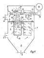
- the device according to the invention consists of a housing 1, which is separated by a partition 2 into a raw gas chamber 3 and a clean gas chamber 4. As many circular openings 5 are provided in the partition 2 as there are filter elements 6.
- the raw gas chamber 3 of the housing 1 is loaded with a raw gas inlet 7 for the dust ne raw gas and provided with a dust discharge 9 for removing the filtered dust.
- the clean gas space 4 has a clean gas outlet 10 for the clean gas.
- Filter elements 6 are suspended in the circular openings 5.
- each inlet nozzle 11 is provided coaxially with the opening of each filter element 6. At its inlet, each inlet nozzle 11 has a radius 12 which points into the clean gas chamber 4 with the curvature outward.
- annular gap injectors 14 with connecting sleeves 15 are attached to the compressed air supply line.
- annular gap injector 14 Arranged on the annular gap injector 14 is an annular channel 16 which opens radially inwardly into an annular gap which is referred to as a “ Coanda” nozzle.
- This gap 17 is smaller than 1 mm and leads radially inwardly to a cylindrical outlet tube 18 of the annular gap injector 14 .
- the cleaned gas is guided through the cylindrical inlet nozzles 11 into the clean gas chamber 4 and from there via the clean gas outlet 10 into the open.
- the filter elements 6 are cleaned at certain intervals of 50 to 300 s by compressed gas during the filtration process.
- the compressed gas is simultaneously blown into the filter elements 6 of a row in the opposite direction to the flow direction of the clean gas 20.
- the compressed gas required for cleaning is generated by a compressed gas compressor (not shown further) and fed to the compressed gas container 21.
- a pressure of 6 bar is present in the compressed gas container 21.
- the compressed gas flow enters the outlet pipes 18 of the first injector stage via the “Coanda” ring gap nozzles 14 and tears secondary gas 23 into the first injector stage.
- the entire purge gas quantity 24, consisting of primary and secondary purge gas quantities, is suddenly pressed into the filter elements 6 via the inlet nozzle 11 and additionally tears a second secondary air quantity 25 suddenly into the filter elements 6.
- a pressure corresponding to the cleaning of the filter elements 6 is built up.
- the dust layer thrown off by the filter elements 6 in this way is collected in the dust collection bunker 8 and discharged from there via the discharge 9. After the magnetically controlled diaphragm valves 22 have closed, the normal filtering flow occurs again for the cleaned filter elements 6.
Landscapes
- Chemical & Material Sciences (AREA)
- Chemical Kinetics & Catalysis (AREA)
- Filtering Of Dispersed Particles In Gases (AREA)
- Cleaning By Liquid Or Steam (AREA)
- Physical Vapour Deposition (AREA)
- Radiation-Therapy Devices (AREA)
- Filtering Materials (AREA)
Priority Applications (1)
| Application Number | Priority Date | Filing Date | Title |
|---|---|---|---|
| AT80103529T ATE9274T1 (de) | 1980-02-07 | 1980-06-24 | Zwei-stufen-injektor zur abgasreinigung von staubfiltern. |
Applications Claiming Priority (2)
| Application Number | Priority Date | Filing Date | Title |
|---|---|---|---|
| DE3004453 | 1980-02-07 | ||
| DE19803004453 DE3004453A1 (de) | 1980-02-07 | 1980-02-07 | Zwei-stufen-injektor zur abgasreinigung von staubfiltern |
Publications (3)
| Publication Number | Publication Date |
|---|---|
| EP0034645A2 EP0034645A2 (de) | 1981-09-02 |
| EP0034645A3 EP0034645A3 (en) | 1982-01-20 |
| EP0034645B1 true EP0034645B1 (de) | 1984-09-12 |
Family
ID=6093959
Family Applications (1)
| Application Number | Title | Priority Date | Filing Date |
|---|---|---|---|
| EP80103529A Expired EP0034645B1 (de) | 1980-02-07 | 1980-06-24 | Zwei-Stufen-Injektor zur Abgasreinigung von Staubfiltern |
Country Status (12)
| Country | Link |
|---|---|
| US (1) | US4356010A (da) |
| EP (1) | EP0034645B1 (da) |
| JP (1) | JPS599206B2 (da) |
| AT (1) | ATE9274T1 (da) |
| BR (1) | BR8005233A (da) |
| CS (1) | CS231170B2 (da) |
| DE (1) | DE3004453A1 (da) |
| DK (1) | DK154751C (da) |
| ES (1) | ES493833A0 (da) |
| HU (1) | HU182167B (da) |
| YU (1) | YU41718B (da) |
| ZA (1) | ZA804275B (da) |
Cited By (2)
| Publication number | Priority date | Publication date | Assignee | Title |
|---|---|---|---|---|
| DE19849639C1 (de) * | 1998-10-28 | 2000-02-10 | Intensiv Filter Gmbh | Coanda-Injektor und Druckgasleitung zum Anschluß eines solchen |
| DE102007047276A1 (de) | 2007-10-02 | 2009-04-09 | Intensiv-Filter Gmbh & Co. Kg | Reinigungsvorrichtung für ein Staubfilter |
Families Citing this family (37)
| Publication number | Priority date | Publication date | Assignee | Title |
|---|---|---|---|---|
| US4578092A (en) * | 1983-11-04 | 1986-03-25 | Wehr Corporation | Method and apparatus for improving the operation of a dust collector |
| DE3412758A1 (de) * | 1984-04-05 | 1985-10-17 | Hölter, Heinz, Dipl.-Ing., 4390 Gladbeck | Heissgasfilter mit vorerhitzungsvorrichtung fuer spuelgase |
| US4666472A (en) * | 1985-10-15 | 1987-05-19 | Wehr Corporation | Dust collector with deflector means |
| US4759781A (en) * | 1987-03-09 | 1988-07-26 | Olson Robert P | Filtering and dust collecting apparatus |
| US4909813A (en) * | 1989-05-30 | 1990-03-20 | Industrial Filter & Pump Mfg. Co. | Jet pulse extender |
| US5173987A (en) * | 1991-04-12 | 1992-12-29 | Abington, Inc. | Rotary air jet screen cleaning device |
| US5562251A (en) * | 1993-09-03 | 1996-10-08 | Goyen Controls & Co. Pty. Limited | Gas nozzle for bag house cleaning systems |
| DE4334699C1 (de) * | 1993-10-12 | 1994-11-17 | Margraf Adolf | Filternder Abscheider |
| CA2187875A1 (en) * | 1994-04-11 | 1995-10-19 | Jeff Elliott | Components for and methods of operation of bag house filter/cartridge cleaning systems |
| DE19701983C1 (de) * | 1997-01-22 | 1998-06-10 | Matthias Luebbers | Ringspaltinjektor |
| KR100242228B1 (ko) * | 1998-03-25 | 2000-02-01 | 최수현 | 고효율 일체형 원심여과집진장치 |
| EP1073507A1 (de) * | 1998-04-24 | 2001-02-07 | Matthias Lübbers | Ringspaltinjektor |
| AU5966899A (en) * | 1998-07-16 | 2000-02-07 | Ft International B.V. | Annular gap injector |
| EP1029576A1 (de) * | 1999-02-18 | 2000-08-23 | Jetclean GmbH | Vorrichtung zur Reinigung eines Filters |
| DE60005406T2 (de) | 2000-02-02 | 2004-07-01 | Niro A/S | Filtereinheit zur gasfiltration |
| DE10041545A1 (de) * | 2000-08-24 | 2002-03-21 | Ft Internat B V | Reinigungseinrichtung für Filterschläuche in einer Filteranlage |
| US7025811B2 (en) * | 2002-08-23 | 2006-04-11 | Cleaire Advanced Emission Controls | Apparatus for cleaning a diesel particulate filter with multiple filtration stages |
| US7799235B2 (en) * | 2004-07-23 | 2010-09-21 | Contech Stormwater Solutions, Inc. | Fluid filter system and related method |
| KR100803721B1 (ko) * | 2006-11-01 | 2008-02-15 | 조광섭 | 공기증폭기를 이용한 압축공기 분사장치 |
| KR100718708B1 (ko) * | 2007-02-08 | 2007-05-15 | (주)안성정기 | 백필터용 인젝터 |
| KR100730305B1 (ko) | 2007-03-09 | 2007-06-19 | 주식회사 삼탑엔지니어링 | 펄스 에어 가속 집진기 |
| CN100512922C (zh) * | 2007-07-05 | 2009-07-15 | 彭志民 | 外滤式袋式除尘器及其清灰方法 |
| US8287726B2 (en) | 2007-08-15 | 2012-10-16 | Monteco Ltd | Filter for removing sediment from water |
| TWI360535B (en) * | 2007-08-30 | 2012-03-21 | Univ Nat Sun Yat Sen | Sulfur-containing compound, method of preparation |
| KR100928591B1 (ko) * | 2009-03-04 | 2009-11-24 | (주)이진엔지니어링 | 압축공기 분사장치 |
| DE102009016145A1 (de) | 2009-04-03 | 2010-10-14 | Intensiv-Filter Gmbh & Co. Kg | Verfahren zur Abreinigung von Filtern |
| CN102811790B (zh) * | 2010-03-24 | 2014-10-15 | 韩国能量技术研究院 | 具有双圆环形槽的清洁空气注射喷嘴和使用它的过滤集尘器的清洁系统 |
| CN101947083A (zh) * | 2010-09-09 | 2011-01-19 | 深圳市康泰健牙科器材有限公司 | 一种牙模车间的吸尘设备及其吸尘方法 |
| JP5574548B2 (ja) * | 2011-11-01 | 2014-08-20 | 東北電機鉄工株式会社 | コアンダインジェクター |
| JP2014012234A (ja) * | 2012-07-03 | 2014-01-23 | Total Business Solution:Kk | バグフィルター清掃用コアンダインジェクター |
| JP5969686B2 (ja) * | 2013-03-08 | 2016-08-17 | 株式会社アクロス商事 | バグフィルター用空気増幅装置および該バグフィルター用空気増幅装置を用いたバグフィルター用空気増幅システム |
| WO2015104827A1 (ja) * | 2014-01-10 | 2015-07-16 | 三菱重工メカトロシステムズ株式会社 | 集塵装置浄化用ノズルおよび集塵装置 |
| JP5722477B2 (ja) * | 2014-03-06 | 2015-05-20 | 東北電機鉄工株式会社 | バグフィルター清掃用コアンダインジェクター |
| US9976501B2 (en) | 2015-10-26 | 2018-05-22 | Ford Global Technologies, Llc | Methods and systems for rotating an exhaust aftertreatment device |
| KR101942639B1 (ko) * | 2017-02-22 | 2019-01-25 | 조광섭 | 대직경 롱 백 필터 탈진장치 |
| GB2592267A (en) * | 2020-02-24 | 2021-08-25 | Altair Uk Ltd | Pulse nozzle for filter cleaning systems |
| JP2023078511A (ja) * | 2021-11-26 | 2023-06-07 | 東北電機鉄工株式会社 | バグフィルター式集塵機 |
Family Cites Families (15)
| Publication number | Priority date | Publication date | Assignee | Title |
|---|---|---|---|---|
| GB812244A (en) * | 1956-07-09 | 1959-04-22 | Metals Disintegrating Co | A gas filtering apparatus |
| NL250037A (da) * | 1959-04-01 | 1900-01-01 | ||
| DE1407922B2 (de) * | 1963-11-18 | 1973-08-16 | Gebruder Buhler AG, Uzwil (Schweiz) | Filteranlage fuer die staubabscheidung aus luft |
| US3535852A (en) * | 1967-11-09 | 1970-10-27 | Hydromation Eng Co | High temperature dust collector |
| US3513638A (en) * | 1968-03-08 | 1970-05-26 | Henry T Young | Filter |
| DE2031011A1 (en) * | 1969-06-23 | 1970-12-23 | Kamas Kvarnmaskiner AB., Malmö (Schweden) | Cleaning dust separation filters |
| DE2003908A1 (de) * | 1970-01-29 | 1971-08-05 | Handte Siegfried Dipl Ing | Vorrichtung zum Reinigen von Filterorganen |
| US3765152A (en) * | 1970-11-04 | 1973-10-16 | Gen Resource Corp | Cleaning of filtering media |
| US3893833A (en) * | 1972-04-26 | 1975-07-08 | Flex Kleen Corp | Compartmented pulse jet dust collector |
| JPS4989961A (da) * | 1972-12-30 | 1974-08-28 | ||
| US3963467A (en) * | 1973-03-08 | 1976-06-15 | Rolschau David W | Dust filter apparatus |
| DE2332031B2 (de) * | 1973-06-23 | 1979-03-22 | Intensiv-Filter Gmbh & Co Kg, 5602 Langenberg | Reinigungsvorrichtung für Gasfilterelemente |
| US3874857A (en) * | 1974-01-07 | 1975-04-01 | Spencer Turbine Co | Apparatus for filtering particulate matter from gas and having reverse flow cleaning means |
| US4073632A (en) * | 1975-07-07 | 1978-02-14 | United States Filter Corporation | Filter bag assembly |
| CH604847A5 (da) * | 1976-01-15 | 1978-09-15 | Ind Patente Anstalt |
-
1980
- 1980-02-07 DE DE19803004453 patent/DE3004453A1/de not_active Ceased
- 1980-06-09 CS CS804060A patent/CS231170B2/cs unknown
- 1980-06-19 YU YU1610/80A patent/YU41718B/xx unknown
- 1980-06-24 EP EP80103529A patent/EP0034645B1/de not_active Expired
- 1980-06-24 AT AT80103529T patent/ATE9274T1/de active
- 1980-07-07 US US06/166,736 patent/US4356010A/en not_active Expired - Lifetime
- 1980-07-10 HU HU801731A patent/HU182167B/hu unknown
- 1980-07-14 DK DK304480A patent/DK154751C/da not_active IP Right Cessation
- 1980-07-15 ZA ZA00804275A patent/ZA804275B/xx unknown
- 1980-07-30 ES ES493833A patent/ES493833A0/es active Granted
- 1980-08-19 BR BR8005233A patent/BR8005233A/pt unknown
- 1980-09-16 JP JP55127341A patent/JPS599206B2/ja not_active Expired
Cited By (2)
| Publication number | Priority date | Publication date | Assignee | Title |
|---|---|---|---|---|
| DE19849639C1 (de) * | 1998-10-28 | 2000-02-10 | Intensiv Filter Gmbh | Coanda-Injektor und Druckgasleitung zum Anschluß eines solchen |
| DE102007047276A1 (de) | 2007-10-02 | 2009-04-09 | Intensiv-Filter Gmbh & Co. Kg | Reinigungsvorrichtung für ein Staubfilter |
Also Published As
| Publication number | Publication date |
|---|---|
| CS231170B2 (en) | 1984-10-15 |
| ZA804275B (en) | 1981-07-29 |
| ES8103993A1 (es) | 1981-04-01 |
| EP0034645A2 (de) | 1981-09-02 |
| DK154751B (da) | 1988-12-19 |
| BR8005233A (pt) | 1981-08-11 |
| YU41718B (en) | 1987-12-31 |
| US4356010A (en) | 1982-10-26 |
| DK154751C (da) | 1989-05-01 |
| YU161080A (en) | 1983-02-28 |
| ATE9274T1 (de) | 1984-09-15 |
| EP0034645A3 (en) | 1982-01-20 |
| CS406080A2 (en) | 1984-02-13 |
| HU182167B (en) | 1983-12-28 |
| ES493833A0 (es) | 1981-04-01 |
| DK304480A (da) | 1981-08-08 |
| JPS56113318A (en) | 1981-09-07 |
| DE3004453A1 (de) | 1981-08-13 |
| JPS599206B2 (ja) | 1984-03-01 |
Similar Documents
| Publication | Publication Date | Title |
|---|---|---|
| EP0034645B1 (de) | Zwei-Stufen-Injektor zur Abgasreinigung von Staubfiltern | |
| DE1757370C3 (de) | Gasfilter | |
| DE102015006497B4 (de) | Zyklonabscheider sowie Filtervorrichtung mit Zyklonabscheider | |
| DE2825273A1 (de) | Abscheider | |
| DE3125503C2 (de) | Vorrichtung zum Klassieren von kugelförmigen elastischen Festkörpern zur Reinigung von Wärmetauscherrohren | |
| DE2328220A1 (de) | Vorrichtung und verfahren zur erzeugung eines wirbels | |
| EP1177828A2 (de) | Vorrichtung zum Abscheiden von Flüssigkeiten und/oder Feststoffen oder Gasen mit anderem spezifischem Gewicht aus einem Gasstrom | |
| DE2332031B2 (de) | Reinigungsvorrichtung für Gasfilterelemente | |
| DE2803224C2 (de) | Selbstreinigende Filtervorrichtung | |
| WO2015055157A1 (de) | Filtersystem mit einem rotationsfilter | |
| DE69418486T2 (de) | Gewebefilter | |
| EP0338314A1 (de) | Pulver-Rückgewinnungseinrichtung für Pulverbeschichtungsanlagen oder dergleichen | |
| DE102013017266A1 (de) | Filtersystem mit einem Rotationsfilter | |
| EP0636049B1 (de) | Vorrichtung zur gleichmässigen verteilung einer zweiphasenströmung | |
| EP1009514B1 (de) | Staubfilter | |
| EP1095688B1 (de) | Staubfilter | |
| AT392419B (de) | Fluessigkeitsfilter | |
| DE202006005677U1 (de) | Vorrichtung zum Reinigen von Rohgas | |
| DE2031011A1 (en) | Cleaning dust separation filters | |
| DE666422C (de) | Vorrichtung zum Abscheiden von Schwebeteilchen, insbesondere von Staub, aus Gasen oder Daempfen | |
| DE2015303A1 (en) | Cleaning dust filters with shock waves | |
| DE202013009217U1 (de) | Filtersystem mit einem Rotationsfilter | |
| DE202013009510U1 (de) | Düsenkopf und Reinigungsvorrichtung mit einem solchen Düsenkopf | |
| DE2652552C3 (de) | Verfahren und Einrichtung zum Regenerieren eines Karkassen-Schlauchfilters | |
| AT350591B (de) | Vorrichtung zur abreinigung von aussen beauf- schlagten filterschlaeuchen |
Legal Events
| Date | Code | Title | Description |
|---|---|---|---|
| PUAI | Public reference made under article 153(3) epc to a published international application that has entered the european phase |
Free format text: ORIGINAL CODE: 0009012 |
|
| AK | Designated contracting states |
Designated state(s): AT BE CH FR GB IT NL SE |
|
| PUAL | Search report despatched |
Free format text: ORIGINAL CODE: 0009013 |
|
| AK | Designated contracting states |
Designated state(s): AT BE CH FR GB IT NL SE |
|
| 17P | Request for examination filed |
Effective date: 19820225 |
|
| ITF | It: translation for a ep patent filed | ||
| GRAA | (expected) grant |
Free format text: ORIGINAL CODE: 0009210 |
|
| AK | Designated contracting states |
Designated state(s): AT BE CH FR GB IT LI NL SE |
|
| REF | Corresponds to: |
Ref document number: 9274 Country of ref document: AT Date of ref document: 19840915 Kind code of ref document: T |
|
| ET | Fr: translation filed | ||
| PLBE | No opposition filed within time limit |
Free format text: ORIGINAL CODE: 0009261 |
|
| 26N | No opposition filed | ||
| ITTA | It: last paid annual fee | ||
| EAL | Se: european patent in force in sweden |
Ref document number: 80103529.6 |
|
| PGFP | Annual fee paid to national office [announced via postgrant information from national office to epo] |
Ref country code: SE Payment date: 19960521 Year of fee payment: 17 |
|
| PG25 | Lapsed in a contracting state [announced via postgrant information from national office to epo] |
Ref country code: SE Effective date: 19970625 |
|
| EUG | Se: european patent has lapsed |
Ref document number: 80103529.6 |
|
| PGFP | Annual fee paid to national office [announced via postgrant information from national office to epo] |
Ref country code: GB Payment date: 19990511 Year of fee payment: 20 |
|
| PGFP | Annual fee paid to national office [announced via postgrant information from national office to epo] |
Ref country code: FR Payment date: 19990512 Year of fee payment: 20 |
|
| PGFP | Annual fee paid to national office [announced via postgrant information from national office to epo] |
Ref country code: CH Payment date: 19990514 Year of fee payment: 20 |
|
| PGFP | Annual fee paid to national office [announced via postgrant information from national office to epo] |
Ref country code: AT Payment date: 19990521 Year of fee payment: 20 |
|
| PGFP | Annual fee paid to national office [announced via postgrant information from national office to epo] |
Ref country code: NL Payment date: 19990527 Year of fee payment: 20 |
|
| PGFP | Annual fee paid to national office [announced via postgrant information from national office to epo] |
Ref country code: BE Payment date: 19990614 Year of fee payment: 20 |
|
| BE20 | Be: patent expired |
Free format text: 20000624 *INTENSIV-FILTER G.M.B.H. & CO K.G. |
|
| PG25 | Lapsed in a contracting state [announced via postgrant information from national office to epo] |
Ref country code: LI Free format text: LAPSE BECAUSE OF NON-PAYMENT OF DUE FEES Effective date: 20000623 Ref country code: GB Free format text: LAPSE BECAUSE OF EXPIRATION OF PROTECTION Effective date: 20000623 Ref country code: CH Free format text: LAPSE BECAUSE OF NON-PAYMENT OF DUE FEES Effective date: 20000623 |
|
| PG25 | Lapsed in a contracting state [announced via postgrant information from national office to epo] |
Ref country code: NL Free format text: LAPSE BECAUSE OF EXPIRATION OF PROTECTION Effective date: 20000624 Ref country code: AT Free format text: LAPSE BECAUSE OF EXPIRATION OF PROTECTION Effective date: 20000624 |
|
| REG | Reference to a national code |
Ref country code: CH Ref legal event code: PL |
|
| REG | Reference to a national code |
Ref country code: GB Ref legal event code: PE20 Effective date: 20000623 |
|
| NLV7 | Nl: ceased due to reaching the maximum lifetime of a patent |
Effective date: 20000624 |