EP0034523B1 - Procédé continu et dispositif de confection de manchon à repli - Google Patents
Procédé continu et dispositif de confection de manchon à repli Download PDFInfo
- Publication number
- EP0034523B1 EP0034523B1 EP81400182A EP81400182A EP0034523B1 EP 0034523 B1 EP0034523 B1 EP 0034523B1 EP 81400182 A EP81400182 A EP 81400182A EP 81400182 A EP81400182 A EP 81400182A EP 0034523 B1 EP0034523 B1 EP 0034523B1
- Authority
- EP
- European Patent Office
- Prior art keywords
- tubular
- guide
- knitted element
- tubular guide
- length
- Prior art date
- Legal status (The legal status is an assumption and is not a legal conclusion. Google has not performed a legal analysis and makes no representation as to the accuracy of the status listed.)
- Expired
Links
- 238000010924 continuous production Methods 0.000 title description 3
- 238000000034 method Methods 0.000 claims description 19
- 238000005520 cutting process Methods 0.000 claims description 10
- 238000011437 continuous method Methods 0.000 claims 1
- 238000009940 knitting Methods 0.000 description 46
- 239000004744 fabric Substances 0.000 description 16
- 238000004519 manufacturing process Methods 0.000 description 10
- 230000009471 action Effects 0.000 description 7
- 230000008569 process Effects 0.000 description 4
- 230000005484 gravity Effects 0.000 description 2
- 239000011324 bead Substances 0.000 description 1
- 230000015572 biosynthetic process Effects 0.000 description 1
- 235000009508 confectionery Nutrition 0.000 description 1
- 229920001971 elastomer Polymers 0.000 description 1
- 230000001788 irregular Effects 0.000 description 1
- 239000000463 material Substances 0.000 description 1
- 230000004048 modification Effects 0.000 description 1
- 238000012986 modification Methods 0.000 description 1
- 239000004033 plastic Substances 0.000 description 1
- 229920003023 plastic Polymers 0.000 description 1
- 230000002787 reinforcement Effects 0.000 description 1
- 239000005060 rubber Substances 0.000 description 1
- 238000009958 sewing Methods 0.000 description 1
- 238000003892 spreading Methods 0.000 description 1
- 230000007480 spreading Effects 0.000 description 1
- 239000000126 substance Substances 0.000 description 1
- 239000004753 textile Substances 0.000 description 1
- 238000009941 weaving Methods 0.000 description 1
Images
Classifications
-
- D—TEXTILES; PAPER
- D06—TREATMENT OF TEXTILES OR THE LIKE; LAUNDERING; FLEXIBLE MATERIALS NOT OTHERWISE PROVIDED FOR
- D06G—MECHANICAL OR PRESSURE CLEANING OF CARPETS, RUGS, SACKS, HIDES, OR OTHER SKIN OR TEXTILE ARTICLES OR FABRICS; TURNING INSIDE-OUT FLEXIBLE TUBULAR OR OTHER HOLLOW ARTICLES
- D06G3/00—Turning inside-out flexible tubular or other hollow articles
Definitions
- the present invention relates to a continuous process for obtaining, from a very long tubular knitting element, a folded sleeve of a given length.
- tubular knitting is used here for convenience and in fact designates any flexible and resistant tubular surface whose physical qualities of extensibility and elasticity are similar to those of knitted textiles, regardless of whether these qualities result or not from weaving or knitting operations, or else from the molecular texture of the material used, as is the case for certain varieties of rubbers and plastics.
- the folded sleeves are in the form of tubular elements, one end of which has been turned over to form a fold, either inside or outside the sleeve. They are used in particular in the field of clothing, where the fold makes it possible to give a clean edge to a sleeve of clothing for example.
- the folding of a sleeve can also serve to hold, hide or protect additional elements such as elastic bracelets, or reinforcement bracelets with which it is desired to provide the end of said sleeves.
- the predetermined dimensions of the folded sleeves which it is desired to obtain are chosen as a function of the use which it is desired to make of it, it being understood that the desired length of the fold is always less than or equal to the given length of the sleeve.
- Double thickness bracelets are of known type and are used for the confection of elements of clothing. These are, for example, cuffs of gloves, ribbing on the sleeves of pullovers or anoraks, turtlenecks, which are sewn to the garment considered; or even double ski caps that are formed by tightening and sewing the upper edge of the bracelet or double sleeve.
- this guide in fact, is supposed to stay in place by its only gravity (it is heavy) when pulling the knit up. It is understood that it is very difficult to obtain such an operation without disturbance for knitting: in fact, if the guide is indeed quite heavy, it strongly presses the knitting against the rollers and the knitting is deformed by pulling it upwards , otherwise risking an irregular cut or double bracelets whose two thicknesses are not the same length. If the guide is not heavy enough, it may get carried away by the ascent of the fabric, which prevents any realization of the process. Naturally, a considerable role is played by the extensibility of knitting, which further complicates the above phenomena.
- the known device is used exclusively for manufacturing double bracelets, the two thicknesses of which are theoretically the same length.
- the invention aims to create a method and a device making it possible to obtain, from a tubular knitting element of great length, a folded sleeve of a given length and this, in a completely mechanized manner and without having the drawbacks of the prior art.
- the invention aims to propose a method and a device allowing a safe and simple cutting of sleeves whose outside fold can be shorter than the length of the sleeve, without risk of jamming.
- the tubular knitting element In the context of a method according to which one end of the tubular knitting element is disposed by guiding it on one of the two surfaces of a tubular guide defining an interior surface and an exterior surface, so that that the free front end of the tubular knitting element exceeds the front end of the tubular guide by a predetermined length, the tubular knitting part projecting backwards, on the other surface of the tubular guide, front end of the tubular guide so as to form the fold of the sleeve and until the second thickness thus turned over has a length equal to the desired length of the fold, then the knitted fabric is pulled forward on the tubular guide of a length at least equal to the given length of the sleeve, increased by the predetermined length, finally, the tubular knitted element is cut transversely at the place delimited by the given length of the sleeve, the method of The invention is characterized in that the tubular knitting element is guided by the inside surface of the tubular guide and in that it is turned over on the outside surface of said guide.
- This process eliminates the need to assign special staff to make the folded sleeves.
- the pace of production is accelerated and operating costs reduced by the mechanization of the station, resulting in the continuous production of folded sleeves.
- This process also ensures a more regular quality of the products thus made compared to the folded sleeves made manually.
- At least one air jet is used which is disposed at the front of the front end of the tubular guide, directed towards the rear of the tubular guide and on the part of tubular knit projecting beyond the end. front of the tubular guide, to prepare the turning of said tubular knitting part.
- the tubular knitting element is guided by the interior surface of the tubular guide, so that the free front end of the tubular knitting element exceeds the front end of the tubular guide.
- a predetermined length preferably between 10 and 15 mm.
- At least one air jet is used directed at the front part of the tubular knit so as to spread the lips formed by said front part.
- the entire knitted fabric is pulled forward with a length equal to the length of the sleeve increased by the predetermined length, preferably between 10 and 15. mm, then the tubular knitted element is cut transversely at the 'place delimited by the desired length of the sleeve; thus prepared, it can be stored or directed to a later stage in the production chain.
- the device for obtaining, from a very long tubular knitting element, a folded sleeve of a given length comprises a tubular guide defining an interior surface and an exterior surface, one of which is used to guide the element of tubular knitting, means for turning back a part of tubular knitting projecting beyond the front end of the tubular guide, means for pulling all of the knitting forward and means for cutting the knitting element transversely tubular. It is characterized in that the inner surface of the tubular guide is intended for guiding the tubular knitting element and in that the means for turning a part of the tubular knitting backwards are capable of turning said part of the knitting onto the outer surface of the tubular guide.
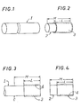
- the method and the device according to the invention are intended to obtain, from a tubular knitting element 1 of great length, a sleeve 2 of given length M, with fold 3 of a desired length L, as shown fig. 1 and 2.
- One of the process steps consists in obtaining a very long element, one end of which is turned over a length L equal to that of the fold to be made, then cutting transversely the tubular knit at the place delimited by the given length of sleeve and indicated by the arrow C in fig. 3, so as to form the sleeve 2 of FIG. 4.
- the fold 3 of knitting is situated above the thickness 4, as shown in FIGS. 3 and 4.
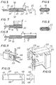
- the tubular knitting element 1 is guided by the interior surface 18 of a tubular guide 19 in order to return it to the exterior surface. 20 of guide 19.
- One end of the tubular knitting element 1 is arranged, guiding it over the inner surface 18 of the tubular guide 19, so that the free front end 21 of the tubular knitting element 1 exceeds the front end 22 of the tubular guide 19 of a predetermined length k between 0 and the desired length L of the fold.
- the front edge of the front part of the tubular knit 1 projecting from the tubular guide by a predetermined length k forms the lips 23 whose configuration is linked to the configuration of the tubular guide.
- At least one air jet 24 (fig. 5) produced by at least one nozzle 25 located at the front of the tubular guide and the tubular knitted fabric, and directed on the front part of the tubular knitted fabric 1, prepares the turning by spreading the less partially the lips 23 in order to facilitate their gripping (fig. 9).
- the lips 23 of the front part of the knitted fabric are then grasped, then they are pulled towards the rear 26 of the tubular guide, according to the arrow E in FIG. 7, and outside this guide, of a length equal to the desired length L of the fold, increased by the predetermined length k.
- the entire knitted fabric is then pulled forward, along the arrow G in FIG. 8, of a length equal to the length of the sleeve M, increased by the predetermined length k, the end of the tubular knit must exceed the front end of the tubular guide before turning. It only remains to cut the tubular knitting element transversely at the location defined by the given length of the sleeve (arrow C in FIG. 8) to form a sleeve which can be stored or taken to a later stage of the production line.
- the remaining tubular knitting element 1 exceeds the predetermined length k making it possible to restart a turning cycle by spacing the lips, pulling the lips backwards, drawing the whole knitting forward, cutting and so on. after.
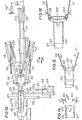
- Figs. 10 to 18 illustrate an embodiment of a device for obtaining, from a tubular knitting element of great length, a folded sleeve of a given length, and implementing the method which has just been explained .
- the device according to the invention comprises a fixed tubular guide 100 defining an inner surface and an outer surface, one of which is used for guiding the tubular knitting element 101 of great length coming from an earlier stage of the production chain; means 102/103 for turning a portion of tubular knitting 104 beyond the front end 105 of the tubular guide 100 backwards; means 106 for pulling the entire knitted fabric 101 forward, along the arrow Av in FIG. 10; and means 107 for transversely cutting the tubular knitting element 101. It further comprises at least one nozzle, such as the nozzles 108 and 109, producing an air jet which cooperates with the means 102/103 to return to the 'rear portion 104 of tubular knit projecting beyond the front end of the tubular guide.
- the means for turning said knitting part 104 backwards comprise two lateral gripping pliers 102 and 103 articulated on arms 110 and 111 and the opening and closing of which are ensured by the action of double-acting jacks 112 and 113 mounted on the arms 110 and 111, transmitted by the rods 114 and 115.
- the two clamps 102 and 103 are located in the median plane of the tubular guide 100, median plane passing through the longitudinal axis 116 of the tubular guide 100, and generally parallel to the largest diameter of a cross section of said guide.
- the two lateral clamps 102 and 103 are located on either side of the longitudinal axis 116 of the guide 100, and they are movable in their plane both parallel and transversely to the longitudinal axis 116 of the fixed tubular guide 100. A To this end, the clamps 102 and 103 are mounted transversely movable and longitudinally fixed on a carriage 117, which is longitudinally movable, thanks to two double-acting cylinders 118 and 118 'mounted in series.
- the arm 110 of the clamp 102 is capable of pivoting in its plane around a pivot 119 of the carriage 117, thus carrying out the transverse movement of the clamp 102, under the action of a double-acting cylinder 120 whose cylinder is linked to the carriage 117 and the rod linked to the arm 110 of the clamp 102.
- the arm 111 of the clamp 103 is capable of pivoting in its plane around a pivot 121 of the carriage 117, under the action of a double-acting cylinder 122 whose cylinder is linked to the carriage 117 and the rod linked to the arm 111 of the clamp 103.
- the means for pulling all of the knitted fabric forward comprise a central gripper 106 (fig. 11) situated in front of the tubular guide 100, preferably on the longitudinal axis 116 of said guide, and movable parallel to this axis longitudinal 116 under the action of a double-acting cylinder 123.
- the central clamp 106 is capable of closing and opening under the action of a double-acting cylinder 138.
- Two nozzles 108 and 109 are placed laterally on either side of the clamp 106 on the same support as it and connected to a compressed air generator, not shown.
- the two nozzles 108 and 109 are longitudinally movable with the central gripper.
- the tubular guide 100 is flattened and has two parallel flat faces 124 and 124 'connected on their longitudinal sides by two substantially semi-cylindrical surfaces 125 and 126 (FIG. 12).
- the parallel flat faces 124 and 124 ′ are provided with notches 127 and 128 which are in alignment with the central gripper 106.
- Two fingers 129 and 130 can enter the tubular guide 100 through holes 131 and 132 drilled on one of the planar faces of the guide. The fingers serve to immobilize the tubular knit 101 inside the tubular guide 100.
- the means for transversely cutting the tubular knitting element comprise a pneumatic knife 107 whose closing then opening are controlled by the jack 134.
- the knife 107 is carried by a carriage 135 movable transversely on a slide 135a under the action of '' a double-acting cylinder 136.
- Figs. 13 to 18 illustrate the operation of the device according to the invention for implementing the method according to the invention from the position shown in FIG. 10.
- the tubular knit 101 is disposed inside the tubular guide 100, so that a knit portion 104 protrudes from the front of the tubular guide by a predetermined length k.
- This predetermined length k is preferably between 10 and 15 mm.
- the nozzles 108 and 109 send air jets directed onto the front part 104 of tubular knitting, so as to at least partially separate the lips formed by said front part 104 from the knitting (FIG. 13).
- the carriage 117 and therefore the clamps 102 and 103 move towards the rear 137 of the tubular guide 100 (arrow Ar in fig. 10) by the outlet of the jack 118 '(fig. 10 and 14), which allows the clamps to be in position to grasp the lips separated from the front part 104 of the tubular knit (fig. 15) and to close by the retraction of the jacks 112 and 113. Thanks to the jack 133, the fingers 129 and 130 disengage from the guide tubular 100 in order to allow the tubular knit 101 to move in the tubular guide 100.
- the clamps 102 and 103 move apart transversely, by pivoting of their arms 110 and 111 under the action of the jacks 120 and 122, still gripping the tubular knit lips (fig. 16).
- the carriage 117 by the outlet of the jack 118, moves rearward 137 of the tubular guide 100, driving the lateral clamps 102 and 103 longitudinally and the end of the tubular knit along the outer surface of the tubular guide 100, to turn around.
- the clamp 106 moves longitudinally rearward 137 (arrow Ar) through the outlet of the jack 123. Even before the clamps 102 and 103 have abandoned the tubular knitting on the tubular guide (fig.
- the clamp 106 has finished moving and is engaged in the notches 127 and 128 of the tubular guide in order to grip the entire knitted fabric with all its thicknesses when it is closed by the jack 138.
- the gripper 106 begins to pull the entire knitted fabric forward (arrow Av) by the retraction of the cylinder 123 just before the clamps 102 and 103 abandon the knitting, which avoids the formation of beads.
- the carriage 117 returns to its initial position by the retraction of the cylinders 118 and 119 (fig. 18).
- the knife 107 It only remains for the knife 107 to advance into the cutting position, while the fingers 129 and 130 engage in the tubular guide 100 and keep the tubular knit stationary, to cut the tubular knit crosswise defined by the length of the sleeve (arrow C), then return to its rest position.
- the clamp 106 then opens and releases the sleeve.
- the plane of the tubular guide and of the clamps is advantageously chosen to be horizontal, so that the sleeve can fall by gravity, and be either stored or taken to a later stage in the production chain.
Landscapes
- Engineering & Computer Science (AREA)
- Mechanical Engineering (AREA)
- Textile Engineering (AREA)
- Treatment Of Fiber Materials (AREA)
- Knitting Machines (AREA)
- Details Of Garments (AREA)
Applications Claiming Priority (2)
| Application Number | Priority Date | Filing Date | Title |
|---|---|---|---|
| FR8002806A FR2475591A1 (fr) | 1980-02-08 | 1980-02-08 | Procede continu et dispositif de confection de manchon a repli |
| FR8002806 | 1980-02-08 |
Publications (2)
| Publication Number | Publication Date |
|---|---|
| EP0034523A1 EP0034523A1 (fr) | 1981-08-26 |
| EP0034523B1 true EP0034523B1 (fr) | 1984-06-06 |
Family
ID=9238374
Family Applications (1)
| Application Number | Title | Priority Date | Filing Date |
|---|---|---|---|
| EP81400182A Expired EP0034523B1 (fr) | 1980-02-08 | 1981-02-05 | Procédé continu et dispositif de confection de manchon à repli |
Country Status (5)
| Country | Link |
|---|---|
| US (1) | US4381068A (enExample) |
| EP (1) | EP0034523B1 (enExample) |
| JP (1) | JPS56128303A (enExample) |
| DE (1) | DE3162631D1 (enExample) |
| FR (1) | FR2475591A1 (enExample) |
Families Citing this family (6)
| Publication number | Priority date | Publication date | Assignee | Title |
|---|---|---|---|---|
| US4480772A (en) * | 1983-02-04 | 1984-11-06 | Kimberly-Clark Corporation | Sleeve making method and apparatus |
| IT1198683B (it) * | 1983-09-19 | 1988-12-21 | Solis Srl | Dispositivo per il caricamento rapido dei collant su macchina di finitura delle calze,specialmente provvista di rovesciatore pneumatico |
| GB8514916D0 (en) * | 1985-06-12 | 1985-07-17 | Copely Dev Ltd | Hose |
| IT1236086B (it) * | 1989-11-03 | 1992-12-22 | Conti Florentia Srl | Metodo e dispositivo per rovesciare le calze da uomo fuori della relativa macchina operatrice |
| US5647517A (en) * | 1995-07-21 | 1997-07-15 | Sara Lee Corporation | Cuff making apparatus |
| US5638998A (en) * | 1995-07-21 | 1997-06-17 | Sara Lee Corporation | Cuff inserting apparatus |
Family Cites Families (9)
| Publication number | Priority date | Publication date | Assignee | Title |
|---|---|---|---|---|
| US2493803A (en) * | 1948-11-23 | 1950-01-10 | Maywood Hosiery Mills Inc | Hosiery inspection device |
| BE552570A (enExample) * | 1956-06-06 | |||
| DE1962993U (de) | 1967-04-05 | 1967-06-29 | Gec Sunvic Regler Gmbh | Standleuchte. |
| DK123683B (da) * | 1968-12-12 | 1972-07-24 | S Fleischer | Apparat til fremstilling af dobbeltfoldede, rørformede dele udfra en rørformet tekstilstofdel, f. eks. en såkaldt rib. |
| US3532258A (en) * | 1969-04-24 | 1970-10-06 | Joseph E Kienel | Hosiery article seam flattening device and method |
| US3887120A (en) * | 1974-09-25 | 1975-06-03 | Marvel Specialty | Hosiery handling method and apparatus |
| GB1482005A (en) * | 1974-10-09 | 1977-08-03 | Hogan J | Turning apparatus for pillow-cases and similar articles |
| US3924785A (en) * | 1974-11-15 | 1975-12-09 | Amf Inc | Hem forming apparatus |
| US4281781A (en) * | 1979-01-15 | 1981-08-04 | Pope William H | Hose everting method and apparatus therefor |
-
1980
- 1980-02-08 FR FR8002806A patent/FR2475591A1/fr active Granted
-
1981
- 1981-02-05 EP EP81400182A patent/EP0034523B1/fr not_active Expired
- 1981-02-05 DE DE8181400182T patent/DE3162631D1/de not_active Expired
- 1981-02-09 JP JP1702481A patent/JPS56128303A/ja active Pending
- 1981-02-09 US US06/233,039 patent/US4381068A/en not_active Expired - Fee Related
Also Published As
| Publication number | Publication date |
|---|---|
| US4381068A (en) | 1983-04-26 |
| FR2475591B1 (enExample) | 1983-05-06 |
| FR2475591A1 (fr) | 1981-08-14 |
| EP0034523A1 (fr) | 1981-08-26 |
| JPS56128303A (en) | 1981-10-07 |
| DE3162631D1 (en) | 1984-07-12 |
Similar Documents
| Publication | Publication Date | Title |
|---|---|---|
| FR2679818A1 (fr) | Procede et dispositif pour la decoupe de plaques de verre plat. | |
| WO2012004462A1 (fr) | Dispositif et procédé de collecte de petits fruits détachés des arbres ou arbustes fruitiers, et machines de récolte comportant un tel dispositif | |
| FR2596948A1 (fr) | Appareil a ebrancher les troncs d'arbres | |
| EP0034523B1 (fr) | Procédé continu et dispositif de confection de manchon à repli | |
| FR2490202A1 (fr) | Appareil pour extraire d'une ligne de transport des articles plats et flexibles, notamment des articles imprimes, entraines a l'aide d'un transporteur | |
| EP2009996A1 (fr) | Machine automatique pour la formation d'un noeud a l'aide d'une ficelle en extremite d'une gaine tubulaire en vue de l'obturer par constriction sous l'effet du serrage du noeud | |
| EP3909430A1 (fr) | Dispositif de mise en portion de saucisses | |
| EP2388199B1 (fr) | Procédé et machine pour ensacher des objets de forme allongée | |
| FR2610646A1 (fr) | Dispositif de sectionnement du fil de trame pour metier a tisser | |
| EP0742684B1 (fr) | Dispositif de repiquage rapide de vegetaux | |
| EP1838593B1 (fr) | Ensemble coherent d'elements elastiques de fixation | |
| EP3476246B1 (fr) | Sangle pectorale | |
| FR2724294A1 (fr) | Machine pour le bridage des volailles | |
| FR2649000A1 (fr) | Ustensile pour ouvrir les huitres | |
| EP1838594B1 (fr) | Dispositif et procede de pose d'un element elastique autour d'un element notamment rectiligne | |
| EP1618242B1 (fr) | Dispositif permettant d'enfiler un article chaussant sur une forme | |
| FR2542584A1 (fr) | Procede et installation pour retourner les slips | |
| FR3058513B1 (fr) | Gilet de protection, notamment porte plaque ou gilet pare-balles a degrafage rapide | |
| EP0908384A1 (fr) | Dispositif pour le cerclage d'un objet ou d'un groupe d'objets au moyen d'un feuillard en matière thermoplastique | |
| FR2671689A1 (fr) | Elagueur. | |
| FR2724822A1 (fr) | Machine a effeuiller les plants de tabac et trier et classer les feuilles par etage foliaire | |
| FR2807286A1 (fr) | Machine pour recolter la lavande ou le lavandin ou autres plantes a tige de taille similaire | |
| FR2672041A1 (fr) | Procede pour la realisation de coussins, matelas ou objets similaires et machine pour sa mise en óoeuvre. | |
| FR2956003A1 (fr) | Dispositif de plantoir | |
| FR2530928A1 (fr) | Appareil a enlever la viande de pilons de volailles |
Legal Events
| Date | Code | Title | Description |
|---|---|---|---|
| PUAI | Public reference made under article 153(3) epc to a published international application that has entered the european phase |
Free format text: ORIGINAL CODE: 0009012 |
|
| AK | Designated contracting states |
Designated state(s): BE DE GB IT SE |
|
| 17P | Request for examination filed |
Effective date: 19820222 |
|
| ITF | It: translation for a ep patent filed | ||
| GRAA | (expected) grant |
Free format text: ORIGINAL CODE: 0009210 |
|
| AK | Designated contracting states |
Designated state(s): BE DE GB IT SE |
|
| REF | Corresponds to: |
Ref document number: 3162631 Country of ref document: DE Date of ref document: 19840712 |
|
| PGFP | Annual fee paid to national office [announced via postgrant information from national office to epo] |
Ref country code: DE Payment date: 19850209 Year of fee payment: 5 |
|
| PLBE | No opposition filed within time limit |
Free format text: ORIGINAL CODE: 0009261 |
|
| STAA | Information on the status of an ep patent application or granted ep patent |
Free format text: STATUS: NO OPPOSITION FILED WITHIN TIME LIMIT |
|
| 26N | No opposition filed | ||
| PG25 | Lapsed in a contracting state [announced via postgrant information from national office to epo] |
Ref country code: SE Effective date: 19860206 |
|
| PG25 | Lapsed in a contracting state [announced via postgrant information from national office to epo] |
Ref country code: BE Effective date: 19860228 |
|
| BERE | Be: lapsed |
Owner name: ANVAR AGENCE NATIONALE DE VALORISATION DE LA RECH Effective date: 19860228 Owner name: INSTITUT TEXTILE DE FRANCE Effective date: 19860228 |
|
| GBPC | Gb: european patent ceased through non-payment of renewal fee | ||
| PG25 | Lapsed in a contracting state [announced via postgrant information from national office to epo] |
Ref country code: DE Effective date: 19861101 |
|
| PG25 | Lapsed in a contracting state [announced via postgrant information from national office to epo] |
Ref country code: GB Effective date: 19881118 |
|
| EUG | Se: european patent has lapsed |
Ref document number: 81400182.2 Effective date: 19861023 |