EP0033753B1 - Verfahren und Vorrichtung zur Verbrennung von locker gelagertem Stroh - Google Patents
Verfahren und Vorrichtung zur Verbrennung von locker gelagertem Stroh Download PDFInfo
- Publication number
- EP0033753B1 EP0033753B1 EP80100932A EP80100932A EP0033753B1 EP 0033753 B1 EP0033753 B1 EP 0033753B1 EP 80100932 A EP80100932 A EP 80100932A EP 80100932 A EP80100932 A EP 80100932A EP 0033753 B1 EP0033753 B1 EP 0033753B1
- Authority
- EP
- European Patent Office
- Prior art keywords
- press
- straw
- cylinder
- burning
- space
- Prior art date
- Legal status (The legal status is an assumption and is not a legal conclusion. Google has not performed a legal analysis and makes no representation as to the accuracy of the status listed.)
- Expired
Links
- 239000010902 straw Substances 0.000 title claims abstract description 75
- 238000000034 method Methods 0.000 title claims abstract description 9
- 238000002485 combustion reaction Methods 0.000 title description 26
- 238000010438 heat treatment Methods 0.000 claims abstract description 6
- 238000005056 compaction Methods 0.000 claims abstract 6
- XLYOFNOQVPJJNP-UHFFFAOYSA-N water Substances O XLYOFNOQVPJJNP-UHFFFAOYSA-N 0.000 claims description 12
- 239000000446 fuel Substances 0.000 claims description 8
- 239000001301 oxygen Substances 0.000 claims description 5
- 229910052760 oxygen Inorganic materials 0.000 claims description 5
- QVGXLLKOCUKJST-UHFFFAOYSA-N atomic oxygen Chemical compound [O] QVGXLLKOCUKJST-UHFFFAOYSA-N 0.000 claims description 3
- 239000000779 smoke Substances 0.000 claims description 3
- 230000008878 coupling Effects 0.000 claims 1
- 238000010168 coupling process Methods 0.000 claims 1
- 238000005859 coupling reaction Methods 0.000 claims 1
- 239000003546 flue gas Substances 0.000 description 9
- 230000006835 compression Effects 0.000 description 5
- 238000007906 compression Methods 0.000 description 5
- UGFAIRIUMAVXCW-UHFFFAOYSA-N Carbon monoxide Chemical compound [O+]#[C-] UGFAIRIUMAVXCW-UHFFFAOYSA-N 0.000 description 3
- 238000005520 cutting process Methods 0.000 description 3
- 238000011144 upstream manufacturing Methods 0.000 description 3
- 239000003344 environmental pollutant Substances 0.000 description 2
- 239000000463 material Substances 0.000 description 2
- 238000002156 mixing Methods 0.000 description 2
- 231100000719 pollutant Toxicity 0.000 description 2
- 241000196324 Embryophyta Species 0.000 description 1
- 240000007829 Haematoxylum campechianum Species 0.000 description 1
- 230000004888 barrier function Effects 0.000 description 1
- 238000010276 construction Methods 0.000 description 1
- 238000004880 explosion Methods 0.000 description 1
- 230000005484 gravity Effects 0.000 description 1
- 238000009413 insulation Methods 0.000 description 1
- 230000001788 irregular Effects 0.000 description 1
- 238000004519 manufacturing process Methods 0.000 description 1
- 238000002360 preparation method Methods 0.000 description 1
- 239000007787 solid Substances 0.000 description 1
- 238000003860 storage Methods 0.000 description 1
- 239000002916 wood waste Substances 0.000 description 1
Images


Classifications
-
- F—MECHANICAL ENGINEERING; LIGHTING; HEATING; WEAPONS; BLASTING
- F24—HEATING; RANGES; VENTILATING
- F24H—FLUID HEATERS, e.g. WATER OR AIR HEATERS, HAVING HEAT-GENERATING MEANS, e.g. HEAT PUMPS, IN GENERAL
- F24H9/00—Details
- F24H9/18—Arrangement or mounting of grates or heating means
- F24H9/1809—Arrangement or mounting of grates or heating means for water heaters
- F24H9/1832—Arrangement or mounting of combustion heating means, e.g. grates or burners
- F24H9/1845—Arrangement or mounting of combustion heating means, e.g. grates or burners using solid fuel
-
- F—MECHANICAL ENGINEERING; LIGHTING; HEATING; WEAPONS; BLASTING
- F23—COMBUSTION APPARATUS; COMBUSTION PROCESSES
- F23G—CREMATION FURNACES; CONSUMING WASTE PRODUCTS BY COMBUSTION
- F23G5/00—Incineration of waste; Incinerator constructions; Details, accessories or control therefor
- F23G5/02—Incineration of waste; Incinerator constructions; Details, accessories or control therefor with pretreatment
-
- F—MECHANICAL ENGINEERING; LIGHTING; HEATING; WEAPONS; BLASTING
- F23—COMBUSTION APPARATUS; COMBUSTION PROCESSES
- F23G—CREMATION FURNACES; CONSUMING WASTE PRODUCTS BY COMBUSTION
- F23G7/00—Incinerators or other apparatus for consuming industrial waste, e.g. chemicals
- F23G7/10—Incinerators or other apparatus for consuming industrial waste, e.g. chemicals of field or garden waste or biomasses
Definitions
- the invention relates to a method and a device for the combustion of loosely stored, bale-shaped straw by means of a continuously loadable combustion device for heating purposes, which is compressed and pushed in a compression direction into the incinerator, where it is burned off at the free entry end.
- Incinerators are known which are used for all types of straw, logs, logs, pressed timber, brushwood, wood waste and the like. Like. Are suitable. These stoves have a large loading door on their front side, which enables compact straw high-pressure bales or round straw bales as well as round or log wood and logs to be inserted into the furnace from the front by hand. The thermal energy obtained by burning the above-mentioned solids is transferred to a hot water circuit and can be used for heating purposes.
- the invention is therefore based on the object of providing a method and a device for burning straw, in which the straw delivered in conventional bales is automatically fed to the oven and burned uniformly in the oven with a high degree of efficiency.
- the overall system should be simple and compact in its construction, i. H. that the space requirement is low and the manufacturing costs are low, and is also intended to ensure safe continuous operation in which the above-mentioned safety risk is excluded.
- This object is achieved according to the invention in that a portion is cut from the bale-shaped straw before combustion and each portion is compressed in two orthogonal planes.
- the compacted portion of straw is then inserted into the incinerator and burned at the free entry end.
- the incinerator therefore works together with a fuel feeding device, which consists of a straw conveyor and a straw compactor, the straw compactor being connected between the straw conveyor and the incinerator and opening directly into the combustion chamber of the incinerator.
- the portioning of the amount of straw to be burned takes place with the aid of a first hydraulic press, the pre-press, which moves transversely to the feed direction of the straw bale and cuts off a straw disk from the front straw bale.
- This straw disc is made by means of the press, which two are moving towards each other Has cylinder half-shells in which pre-compresses when closing the press cylinder space.
- a post-press adjoining the pre-press now pushes the pre-compacted straw through a further cylinder space of the post-press, the straw being further compressed in the feed direction by the frictional forces between the straw and the cylinder wall.
- oxygen and moisture can also be extracted from the straw. Since the cylinder chamber of the postpress is directly connected to the combustion chamber of the incinerator, the compacted, cylindrical straw mass is pushed directly into the combustion chamber, where the free end starts to burn and then falls and falls apart on a grate located at the lower part of the combustion chamber .
- an extinguishing device is additionally provided, which is formed by water nozzles arranged in a ring in the cylinder wall, which are connected to a pressurized water line via a thermostatically controlled shut-off valve. This shut-off valve is opened when the temperature prevailing in the cylinder space of the post-press should exceed a certain limit value.
- the pressure pistons of the two presses are coupled to one another and also to the drive of the straw conveyor in such a way that the combustion chamber is continuously fed with fresh straw. It is only necessary to ensure that appropriate straw bales are placed on the straw conveyor.
- the incinerator Since the emission of pollutants is usually greatest when the cold incinerator is started, the incinerator is also equipped with a special device that can be operated via a rotary valve so that the flue gases are either diverted directly into the chimney or by moving the rotary valve can be used to improve the emission values.
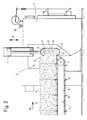
- the device shown in FIGS. 1 and 2 essentially consists of the incinerator 1 and the fuel feed device 2.
- the fuel feed device 2 in turn has a straw conveyor device as well as a pre-press 4 and a post-press 5.
- the straw conveyor 3 is formed by a chain conveyor with conveyor chains 6 and drive sprockets 7. On different chain links there are drivers 8 which are arranged at a distance from one another and move the straw bales 9 in the direction of the arrow 10 to the pre-press 4.
- the chain conveyor pushes the front straw bale onto a cutting table 11, to which the lower cylinder shell half 12 of the pre-press 4 is directly connected.
- the drivers 8 are returned around the drive sprocket 7, immersing them in corresponding guide slots on the cutting table.
- the front straw bale 13 is then transported on through the advancing straw bale.
- the conveyor chain 6 is driven at intervals by the drive sprocket 7, the drive being coupled to the press drive in the manner described later.
- the upper cylinder shell half 14 of the press is in the open position, in which the straw bale 13 between the two cylinder shell halves 12 and 14 can be inserted with its front end against a wall 15 on the front side.
- the upper cylinder shell half 14 has already moved somewhat downward in the direction of arrow 16, with blades 17 provided on the edges of the cylinder half shell 14 having separated a portion 18 of straw from the straw bale 13. This portion 18 is compressed in the cylinder space that is formed (shown in dashed lines).
- FIG. 1 shows that the lower half of the cylinder shell 12 also represents part of the press cylinder 19 of the secondary press 5.
- the piston of this secondary press which is shown in broken lines in FIG. 1 in its left end position, moves in the direction of arrow 20 with respect to FIG. 1 to the right and pushes the pre-compressed straw into the press cylinder 19, which is directly in the combustion chamber 21 of the incinerator 1 opens and is closed at its free end by a flap 22.
- the pre-compressed straw is compressed in the press cylinder 19 for the second time, to which the frictional forces occurring between the straw and the press cylinder wall and the forces to open the drop flap 22 contribute.
- the strength of the compression in the secondary press can be influenced in that the press cylinder 19 is given a corresponding length or z. B. tapered towards the incinerator 1.
- the piston 23 can have a cutting edge 24 on its front edge, which makes it easier to cut through straw residues in the closing area of the upper cylinder shell half 14. It is also conceivable that the piston 23 has a jacket bush 25 shown in dashed lines, which closes the opening of the press cylinder 19 in the region of the pre-press 4 when the piston 23 moves to the right in relation to FIG. 1. This has the advantage that the cylinder shell half 14 can already be moved upwards into the open position while the piston 23 moves back into its initial position, since the jacket bush prevents straw from falling behind the piston 23.
- the combustion chamber 21 is continuously fed with the straw compressed for the second time in the postpress 5, which is pushed into the combustion chamber 21 intermittently with the aid of the piston 23. At the same time, pieces of straw fall onto a grate 26 located in the lower part of the combustion chamber 21, with thorough mixing with air taking place and clean combustion being ensured. Since the press cylinder 19 is filled with low-oxygen compressed straw, a flashback from the combustion chamber 21 into the press cylinder 19 is prevented. If the front part of the straw that has been pushed out has burned down and no further straw has been pushed in, the drop flap 22 automatically closes under the action of gravity, so that the press cylinder 19 is closed.
- the thermostat 27 If the temperature in the press cylinder 19 should exceed a certain limit value, this is sensed by the thermostat 27 and the thermostat sends a control signal to a control device, not shown, which opens a shut-off valve 28 of a pressurized water line 29 so that water through the nozzles 30 is introduced into the press cylinder 19. Since the nozzles 30 are arranged in a ring in the wall of the press cylinder 19, the water barrier generated prevents the straw from burning through to the pre-press.
- the combustion furnace 1 shown in section in FIGS. 1, 3 and 4 is used for hot water preparation and for this purpose has an inner fire socket 31 and an outer jacket 32, which is coated with insulation 33.
- the water to be heated circulates between the inner fire socket 31 and the outer jacket 32.
- the incinerator has a flue gas convector 34 with a rotary slide 35 which can be moved in the direction of the arrows 36.
- the rotary valve 35 is set such that the smoke in the direction of arrows 37 through an opening 38 of an exhaust pipe 39 through along the lower part of the pipe 39 to the front end of the incinerator 1 and back in the upper part of the pipe 39 to is directed to the chimney 40.
- This position of the rotary valve 35 is set in the burning phase of the furnace in which the chimney is at its operating temperature.
- the hot flue gases cool down as they flow through the exhaust pipe 39 by releasing their heat to the water jacket which surrounds the flue gas convector. When the flue gases enter the chimney, their temperature has cooled down so much that even older chimney structures can no longer be damaged by high flue gas temperatures.
- FIG 4 shows the other position of the rotary valve 35, in which a direct connection is established between the opening 38 and the chimney 40, while the exhaust pipe 39 is closed in the upper part.
- This position of the rotary valve 35 is selected in the heating phase of the furnace, so that the hot flue gases or flames can bring the chimney directly to its operating temperature.
- a thermostat 41 is provided in the region of the convector 34, via which the entire system is switched on or off when a predetermined temperature range is exceeded or fallen below.
Landscapes
- Engineering & Computer Science (AREA)
- Mechanical Engineering (AREA)
- General Engineering & Computer Science (AREA)
- Environmental & Geological Engineering (AREA)
- Thermal Sciences (AREA)
- Sustainable Energy (AREA)
- Sustainable Development (AREA)
- Physics & Mathematics (AREA)
- Life Sciences & Earth Sciences (AREA)
- Chemical & Material Sciences (AREA)
- Combustion & Propulsion (AREA)
- Solid-Fuel Combustion (AREA)
- Fertilizers (AREA)
- Portable Nailing Machines And Staplers (AREA)
- Regulation And Control Of Combustion (AREA)
- Filtering Of Dispersed Particles In Gases (AREA)
Description
- Die Erfindung betrifft ein Verfahren und eine Vorrichtung zur Verbrennung von locker gelagertem, ballenförmig angeliefertem Stroh mittels einer kontinuierlich beschickbaren Verbrennungsvorrichtung für Heizzwecke, welches verdichtet und in einer Verdichtungsrichtung in den Verbrennungsofen geschoben wird, wo es am freien Eintrittsende abgebrannt wird.
- Es sind Verbrennungsöfen bekannt, die für alle Arten von Stroh, Scheitholz, Rundholz, Preßholz, Reisig, Holzabfälle u. dgl. geeignet sind. Diese Öfen besitzen an ihrer Vorderseite eine große Beschickungstür, die es ermöglicht, daß kompakte Stroh-Hochdruckballen oder Stroh-Rundballen sowie Rund- oder Scheitholz und Stammholz von der Vorderseite in den Ofen von Hand eingeführt werden kann. Die durch das Verbrennen der vorgenannten Feststoffe erzielte Wärmeenergie wird an einen Warmwasserkreislauf übertragen und ist zu Heizzwecken ausnutzbar. Es hat sich jedoch gezeigt, daß die Verbrennung von kompakten Stroh-Hochdruckballen oder Stroh-Rundballen schlecht ist, da die Flammen nur an der Außenseite des jeweiligen Ballens angreifen können, während das Strohmaterial in den sauerstoffarmen und gegebenenfalls feuchten inneren Zonen überhaupt nicht brennt oder nur schwelt, so daß der Gesamtwirkungsgrad der Anlage verringert wird. Außerdem ergibt sich durch die schlechte Verbrennung eine erhebliche Belastung der Umwelt durch den starken Emissionsanteil von Schadstoffen.
- Zur Vermeidung oben beschriebener Nachteile ist es bekannt, dem Verbrennungsofen eine Zerreißanlage vorzuschalten, durch welche die Strohballen mit einem Häcksler aufgelockert und gegebenenfalls das Stroh in den Ofen unter Verwendung von Druckluft eingeblasen wird. Die Verbrennung ist infolge der guten Durchmischung des Brennmaterials mit Sauerstoff wesentlich verbessert, jedoch ergibt sich bei dieser Anlage ein weiterer wesentlicher Nachteil, da die Gefahr einer Explosion bzw. eines Flammenrückschlages bis in die Zerreißanlage nicht mit Sicherheit unterbunden werden kann. Der Wirkungsgrad eines vorbeschriebenen Ofens ist zwar gut, jedoch arbeitet ein solcher Ofen mit einem erheblichen Sicherheitsrisiko. Darüber hinaus ist die Gesamtanlage wegen der vorgeschalteten Zerreißanlage hinsichtlich des Raumbedarfs aufwendig und teuer.
- Durch die GB-A-2 021 256 ist eine kontinuierlich beschickbare Verbrennungseinrichtung bekanntgeworden, bei welcher in einen Vorratsbehälter aufgegebene Strohballen mittels einer Reißkette in lockeres Stroh zerrissen werden. Dieses lockere Stroh fällt ungesteuert in einen Trichter und von diesem in ein darunter liegendes Rohr. Diese Einrichtung besitzt den Nachteil, daß es mehr oder weniger dem Zufall überlassen bleibt, welche Strohmenge durch die Öffnung in das darunter liegende Rohr gelangt. Es ist ferner nicht gewährleistet, daß das Stroh in einer konstanten Dichte dem Brennofen zugeführt wird, so daß eine unregelmäßige Verbrennung stattfindet. Schließlich ist das in den Ofen einmündende Rohr gegenüber der Brennkammer nicht verschließbar, so daß ein Flammenrückschlag nicht unterbunden wird und ein erhebliches Sicherheitsrisiko auftritt.
- Durch die US-A-3 818 848 ist eine Verbrennungsvorrichtung mit vorgeschalteter Beschikkungsvorrichtung bekanntgeworden, bei welcher der Vorschub des Brennmaterials mittels zweier Verdichtungskolben erfolgt, die über ein Kurbelgestänge mit einer Schwungscheibe verbunden sind. Das bedeutet, daß immer eine gleichzeitige Bewegung der beiden Kolben stattfindet, so daß sich keine gleichmäßige Verdichtung des Brennmaterials ergibt. Wird nämlich der eine Kolben vorgeschoben, dann öffnet der andere Kolben die Beschickungskammer, so daß Brennmaterial über einen Trichter nachfallen kann. Die bekannte Beschickungsvorrichtung ist daher weniger als Vorverdichtungsvorrichtung geeignet, sondern dient vielmehr lediglich als Fördereinrichtung für das Verbrennungsmaterial.
- Der Erfindung liegt daher die Aufgabe zugrunde, ein Verfahren und eine Vorrichtung zur Verbrennung von Stroh zu schaffen, bei welcher das in herkömmlichen Ballen angelieferte Stroh dem Ofen automatisch zugeführt und in dem Ofen mit einem hohen Wirkungsgrad gleichmäßig verbrannt wird. Die Gesamtanlage soll in ihrem Aufbau einfach und kompakt sein, d. h. daß der Platzbedarf gering und die Herstellungskosten niedrig sind, und soll darüber hinaus einen sicheren Dauerbetrieb gewährleisten, bei welchem das oben erwähnte Sicherheitsrisiko ausgeschlossen ist.
- Diese Aufgabe wird gemäß der Erfindung dadurch gelöst, daß von dem ballenförmig angelieferten Stroh vor der Verbrennung eine Portion abgeschnitten und jede Portion in zwei orthogonalen Ebenen verdichtet wird. Die verdichtete Strohportion wird dann in den Verbrennungsofen eingeschoben und am freien Eintrittsende abgebrannt. Der Verbrennungsofen arbeitet daher mit einer Brennstoffbeschickungsvorrichtung zusammen, welche aus einer Strohfördereinrichtung und einer Strohverdichtungseinrichtung besteht, wobei die Strohverdichtungseinrichtung zwischen die Strohfördereinrichtung und den Verbrennungsofen geschaltet ist und direkt in die Brennkammer des Verbrennungsofens einmündet. Die Portionierung der zu verbrennenden Strohmenge erfolgt mit Hilfe einer ersten hydraulischen Presse, der Vorpresse, welche sich quer zur Zuführrichtung der Strohballen bewegt und von dem vorderen Strohballen eine Strohscheibe abschneidet. Diese Strohscheibe wird mittels der Presse, welche zwei sich aufeinander zu bewegende Zylinderhalbschalen besitzt, in dem sich beim Schließen der Presse bildenden Zylinderraum vorverdichtet.
- Eine sich an die Vorpresse anschließende Nachpresse schiebt nun das vorverdichtete Stroh durch einen weiteren Zylinderraum der Nachpresse hindurch, wobei das Stroh durch die zwischen dem Stroh und der Zylinderwandung herrschenden Reibungskräfte in Vorschubrichtung weiter verdichtet wird. In dieser Nachpresse kann dem Stroh ferner Sauerstoff und Feuchtigkeit entzogen werden. Da der Zylinderraum der Nachpresse mit der Brennkammer des Verbrennungsofens unmittelbar in Verbindung steht, wird die verdichtete zylinderförmig geformte Strohmasse direkt in die Brennkammer eingeschoben, wo das freie Ende zu brennen beginnt und dann auf einen sich am unteren Teil der Brennkammer befindlichen Rost herunter-und auseinanderfällt. Da das vordere, in die Brennkammer des Verbrennungsofens hineinragende Ende der Nachpresse durch eine Fallklappe verschlossen ist und darüber hinaus der Zylinderraum der Nachpresse mit sauerstoffarmem verdichtetem Stroh gefüllt ist, wird ein Flammenrückschlag aus der Brennkammer in die Beschickungsvorrichtung unterbunden. Es ist jedoch zusätzlich noch eine Löscheinrichtung vorgesehen, die von in der Zylinderwandung ringförmig angeordneten Wasserdüsen gebildet ist, welche über einen thermostatgesteuerten Absperrhahn an eine Druckwasserleitung angeschlossen sind. Dieser Absperrhahn wird dann geöffnet, wenn die in dem Zylinderraum der Nachpresse herrschende Temperatur einen bestimmten Grenzwert überschreiten sollte.
- Die Druckkolben der beiden Pressen sind untereinander und ferner mit dem Antrieb der Strohfördereinrichtung derart gekoppelt, daß die Brennkammer kontinuierlich mit frischem Stroh beschickt wird. Es ist lediglich dafür zu sorgen, daß entsprechende Strohballen auf der Strohfördereinrichtung abgelegt werden.
- Da die Emission von Schadstoffen bei Inbetriebnahme des kalten Verbrennungsofens in der Regel am größten ist, ist der Verbrennungsofen darüber hinaus mit einer besonderen Vorrichtung ausgestattet, die über einen Drehschieber derart betätigbar ist, daß die Rauchgase entweder direkt in den Schornstein oder durch Umstellung des Drehschiebers umgeleitet werden können, um die Emissionswerte zu verbessern.
- Weitere Merkmale, Einzelheiten und Vorteile der Erfindung ergeben sich aus der nachfolgenden Beschreibung eines bevorzugten Ausführungsbeispiels anhand der Zeichnung. Darin zeigt
- Fig. 1 eine schematische Schnittdarstellung durch die Gesamtanlage,
- Fig. 2 eine Seitenansicht der in der Fig. 1 dargestellten Anlage,
- Fig. einen schematischen Teilschnitt durch den Verbrennungsofen, wobei der Drehschieber derart eingestellt ist, daß die Rauchgase umgelenkt werden, und
- Fig. 4 eine zweite Einstellung des Drehschiebers derart, daß die Rauchgase direkt in den Schornstein gelangen.
- Die in den Fig. 1 und 2 dargestellte Vorrichtung besteht im wesentlichen aus dem Verbrennungsofen 1 und der Brennstoffbeschickungsvorrichtung 2. Die Brennstoffbeschickungsvorrichtung 2 weist ihrerseits eine Strohfördereinrichtung sowie eine Vorpresse 4 und eine Nachpresse 5 auf.
- Die Strohfördereinrichtung 3 ist von einem Kettenförderer mit Förderketten 6 und Antriebskettenrädern 7 gebildet. An verschiedenen Kettengliedern befinden sich im Abstand zueinander angeordnete Mitnehmer 8, welche die Strohballen 9 in Richtung des Pfeiles 10 zur Vorpresse 4 bewegen. Der Kettenförderer schiebt den vorderen Strohballen auf einen Schneidetisch 11, an welchen sich die untere Zylinderschalenhälfte 12 der Vorpresse 4 unmittelbar anschließt. Die Mitnehmer 8 werden um das Antriebskettenrad 7 herum zurückgeführt, wobei sie in entsprechende Führungsschlitze des Schneidetisches nach unten eintauchen. Der vordere Strohballen 13 wird dann durch den nachrückenden Strohballen weitertransportiert.
- Die Förderkette 6 wird durch das Antriebskettenrad 7 intervallartig angetrieben, wobei der Antrieb in der später noch beschriebenen Weise mit dem Pressenantrieb gekoppelt ist.
- In der Fig. 1 befindet sich die obere Zylinderschalenhälfte 14 der Presse in der Öffnungsstellung, in welcher der Strohballen 13 zwischen die beiden Zylinderschalenhälften 12 und 14 mit seinem vorderen Ende gegen eine Wand 15 stirnseitig einschiebbar ist. Bei der Darstellung gemäß Fig. 2 hat sich die obere Zylinderschalenhälfte 14 in Pfeilrichtung 16 bereits etwas nach unten bewegt, wobei an den Rändern der Zylinderhalbschale 14 vorgesehene Schneiden 17 eine Portion 18 Stroh von dem Strohballen 13 abgetrennt haben. Diese Portion 18 wird in dem sich ausbildenden Zylinderraum (gestrichelt dargestellt) komprimiert.
- Die Fig. 1 läßt erkennen, daß die untere Zylinderschalenhälfte 12 gleichzeitig einen Teil des Pressenzylinders 19 der Nachpresse 5 darstellt. Der Kolben dieser Nachpresse, der in der Fig. 1 in seiner linken Endstellung strichpunktiert dargestellt ist, bewegt sich in Richtung des Pfeiles 20 in bezug auf die Fig. 1 nach rechts und schiebt das vorkomprimierte Stroh in den Pressenzylinder 19, welcher direkt in die Brennkammer 21 des Verbrennungsofens 1 einmündet und an ihrem freien Ende durch eine Fallklappe 22 verschlossen ist. Das vorkomprimierte Stroh wird in dem Pressenzylinder 19 zum zweitenmal komprimiert, wozu die zwischen dem Stroh und der Pressenzylinderwand auftretenden Reibungskräfte sowie die Kräfte zum Aufstoßen der Fallklappe 22 beitragen.
- Die Stärke der Verdichtung in der Nachpresse ist dadurch beeinflußbar, daß der Pressenzylinder 19 eine entsprechende Länge erhält oder sich z. B. in Richtung zum Verbrennungsofen 1 verjüngt.
- Der Kolben 23 kann an seinem stirnseitigen Rand eine Schneide 24 aufweisen, die das Durchtrennen von Strohresten im Schließbereich der oberen Zylinderschalenhälfte 14 erleichtert. Es ist ferner auch denkbar, daß der Kolben 23 eine gestrichelt dargestellte Mantelbuchse 25 aufweist, welche die Öffnung des Pressenzylinders 19 im Bereich der Vorpresse 4 verschließt, wenn sich der Kolben 23 in bezug auf die Fig. 1 nach rechts bewegt. Das hat den Vorteil, daß die Zylinderschalenhälfte 14 bereits nach oben in die Öffnungsstellung bewegbar ist, während sich der Kolben 23 in seine Ausgangsstellung zurückbewegt, da durch die Mantelbuchse verhindert wird, daß Stroh hinter den Kolben 23 fallen kann.
- Die Brennkammer 21 wird kontinuierlich mit dem zum zweiten Mal in der Nachpresse 5 komprimierten Stroh beschickt, welches mit Hilfe des Kolbens 23 taktweise in die Brennkammer 21 eingeschoben wird. Gleichzeitig fallen Strohteile auf einen sich im unteren Teil der Brennkammer 21 befindlichen Rost 26, wobei eine gute Durchmischung mit Luft erfolgt und eine saubere Verbrennung gewährleistet ist. Da der Pressenzylinder 19 mit sauerstoffarmem komprimiertem Stroh gefüllt ist, wird ein Flammenrückschlag aus der Brennkammer 21 in den Pressenzylinder 19 verhindert. Sollte der vordere Teil des ausgeschobenen Strohs abgebrannt sein, und kein weiteres Stroh nachgeschoben werden, dann fällt die Fallklappe 22 unter Einwirkung der Schwerkraft automatisch zu, so daß der Pressenzylinder 19 verschlossen wird. Wenn die Temperatur in dem Pressenzylinder 19 einen bestimmten Grenzwert übersteigen sollte, dann wird dies von dem Thermostaten 27 erfaßt und von dem Thermostaten ein Steuersignal an eine nicht dargestellte Steuereinrichtung abgegeben, welche einen Absperrhahn 28 einer Druckwasserleitung 29 öffnet, so daß Wasser durch die Düsen 30 in den Pressenzylinder 19 eingeleitet wird. Da die Düsen 30 ringförmig in der Wandung des Pressenzylinders 19 angeordnet sind, wird durch die erzeugte Wassersperre ein Durchbrennen des Strohs bis zur Vorpresse verhindert.
- Der in den Fig. 1, 3 und 4 im Schnitt dargestellte Verbrennungsofen 1 dient zur Warmwasserbereitung und besitzt zu diesem Zweck eine innere Feuerbuchse 31 und einen äußeren Mantel 32, welcher mit einer Isolierung 33 beschichtet ist. Zwischen der inneren Feuerbuchse 31 und dem äußeren Mantel 32 zirkuliert das zu erwärmende Wasser.
- Im oberen Teil besitzt der Verbrennungsofen einen Rauchgaskonvektor 34 mit einem Drehschieber 35, welcher in Richtung der Pfeile 36 bewegbar ist. In der Fig. 3 ist der Drehschieber 35 derart eingestellt, daß der Rauch in Richtung der Pfeile 37 durch eine Öffnung 38 eines Abgasrohres 39 hindurch entlang dem unteren Teil des Rohres 39 zur vorderen Stirnseite des Verbrennungsofens 1 und zurück im oberen Teil des Rohres 39 bis zum Schornstein 40 geleitet wird. Diese Stellung des Drehschiebers 35 wird in der Brennphase des Ofens eingestellt, in welcher der Schornstein seine Betriebstemperatur aufweist. Die heißen Rauchgase kühlen sich beim Durchströmen des Abgasrohres 39 ab, indem sie ihre Wärme an den Wassermantel, welcher den Rauchgaskonvektor umgibt, abgeben. Wenn die Rauchgase in den Schornstein eintreten, ist ihre Temperatur so weit heruntergekühlt, daß auch ältere Schornsteinkonstruktionen durch hohe Rauchgastemperaturen nicht mehr beschädigt werden können.
- In der Fig.4 ist die andere Stellung des Drehschiebers 35 gezeigt, bei welcher eine direkte Verbindung zwischen der Öffnung 38 und dem Schornstein 40 hergestellt wird, während das Abgasrohr 39 im oberen Teil verschlossen ist. Diese Stellung des Drehschiebers 35 wird in der Anheizphase des Ofens gewählt, so daß die heißen Rauchgase bzw. Flammen den Schornstein direkt auf seine Betriebstemperatur bringen können.
- Aus der Fig. 1 ist noch zu entnehmen, daß im Bereich des Konvektors 34 ein Thermostat 41 vorgesehen ist, über welchen die Gesamtanlage ein- bzw. abgeschaltet wird, wenn ein vorgegebener Temperaturbereich unter- bzw. überschritten wird.


Claims (17)
Priority Applications (1)
| Application Number | Priority Date | Filing Date | Title |
|---|---|---|---|
| AT80100932T ATE6093T1 (de) | 1980-02-11 | 1980-02-25 | Verfahren und vorrichtung zur verbrennung von locker gelagertem stroh. |
Applications Claiming Priority (2)
| Application Number | Priority Date | Filing Date | Title |
|---|---|---|---|
| DE19803005039 DE3005039A1 (de) | 1980-02-11 | 1980-02-11 | Verfahren und vorrichtung zur verbrennung von locker gelagerten feststoffen |
| DE3005039 | 1980-02-11 |
Publications (3)
| Publication Number | Publication Date |
|---|---|
| EP0033753A2 EP0033753A2 (de) | 1981-08-19 |
| EP0033753A3 EP0033753A3 (en) | 1981-08-26 |
| EP0033753B1 true EP0033753B1 (de) | 1984-02-01 |
Family
ID=6094319
Family Applications (1)
| Application Number | Title | Priority Date | Filing Date |
|---|---|---|---|
| EP80100932A Expired EP0033753B1 (de) | 1980-02-11 | 1980-02-25 | Verfahren und Vorrichtung zur Verbrennung von locker gelagertem Stroh |
Country Status (5)
| Country | Link |
|---|---|
| EP (1) | EP0033753B1 (de) |
| AT (1) | ATE6093T1 (de) |
| DE (1) | DE3005039A1 (de) |
| DK (1) | DK109580A (de) |
| NO (1) | NO800530L (de) |
Cited By (1)
| Publication number | Priority date | Publication date | Assignee | Title |
|---|---|---|---|---|
| WO2003050450A1 (en) * | 2001-12-11 | 2003-06-19 | Sugar Research Limited | Feeder for injecting fibrous biomass fuels into a reactor at atmospheric pressure or into a pressurized reactor |
Families Citing this family (12)
| Publication number | Priority date | Publication date | Assignee | Title |
|---|---|---|---|---|
| FR2535647A1 (fr) * | 1982-11-04 | 1984-05-11 | Gonod Andre | Appareil pour la fabrication d'elements combustibles a partir de dechets organiques |
| DE3302380A1 (de) * | 1983-01-25 | 1984-07-26 | Gebrüder Welger GmbH & Co KG, 3340 Wolfenbüttel | Beschickungsvorrichtung fuer stroh-verbrennungsanlagen |
| DE3311415A1 (de) * | 1983-03-29 | 1984-10-04 | Gebrüder Welger GmbH & Co KG, 3340 Wolfenbüttel | Beschickungsvorrichtung fuer stroh-verbrennungsanlagen |
| SE8601091L (sv) * | 1986-03-10 | 1987-09-11 | Rippelton Nv | Sett och anordning for att dosera ett jemnt flode av fastbrensle |
| ATE192016T1 (de) * | 1993-02-25 | 2000-05-15 | Cargill Inc | Brassica mit niedrigem glucosinolate gehalt |
| DK172334B1 (da) * | 1995-06-21 | 1998-03-23 | Ansaldo Volund As | Fremgangsmåde og aggregat til brug ved fremstilling og forbrænding af et brændbart blandingsprodukt |
| AT510511A1 (de) * | 2010-09-17 | 2012-04-15 | Hinterecker Claus Ing | Vorrichtung zur einbringung von biomaterial in einen brenn- oder vergaserraum |
| ES2597235B1 (es) * | 2015-07-14 | 2017-12-12 | José María GARCÍA GÓMEZ | Dispositivo inyector para calderas de biomasa |
| CN105627293A (zh) * | 2016-03-10 | 2016-06-01 | 马少辉 | 一种生物质转化装置 |
| RU2633849C1 (ru) * | 2016-05-25 | 2017-10-18 | Федеральное государственное бюджетное научное учреждение Всероссийский научно-исследовательский институт механизации сельского хозяйства (ФГБНУ ВИМ) | Способ сжигания растительных отходов |
| CN106678817B (zh) * | 2017-01-24 | 2018-10-16 | 成都君华睿道科技有限公司 | 一种压实焚烧两用固体废物处理装置 |
| DE102017119897A1 (de) | 2017-08-30 | 2019-02-28 | Rolf Goldschmidt | Verbrennungsmaterial |
Family Cites Families (9)
| Publication number | Priority date | Publication date | Assignee | Title |
|---|---|---|---|---|
| US2011620A (en) * | 1931-11-09 | 1935-08-20 | Clarcnce F Erb | Heating furnace |
| FR1114438A (fr) * | 1954-10-06 | 1956-04-12 | Foyer-brûleur pour échangeurs de faible puissance | |
| CH416999A (de) * | 1964-04-22 | 1966-07-15 | Guenter Dipl Ing Fuchs | Kessel, insbesondere für Heizzwecke |
| US3570421A (en) * | 1969-04-16 | 1971-03-16 | Mini Municipals Inc | Loader apparatus for loading incinerators and the like |
| US3818848A (en) * | 1971-07-19 | 1974-06-25 | O Gardner | Burner for light combustible materials |
| CH560367A5 (en) * | 1973-09-11 | 1975-03-27 | Ghelfi Ag | Charging system for refuse incinerator furnace - separates air and fuel region of combustion chamber from charging arrangement |
| FR2295349A1 (fr) * | 1974-12-19 | 1976-07-16 | Anvar | Appareil a bruler de la paille ou des substances similaires |
| FR2366929A1 (fr) * | 1976-10-06 | 1978-05-05 | Wetstein Leon | Presse pour l'agglomeration des dechets |
| DE2821767A1 (de) * | 1978-05-18 | 1979-11-22 | Josef Probsteder | Ofen fuer feste abfallbrennstoffe |
-
1980
- 1980-02-11 DE DE19803005039 patent/DE3005039A1/de not_active Withdrawn
- 1980-02-25 EP EP80100932A patent/EP0033753B1/de not_active Expired
- 1980-02-25 AT AT80100932T patent/ATE6093T1/de active
- 1980-02-26 NO NO800530A patent/NO800530L/no unknown
- 1980-03-14 DK DK109580A patent/DK109580A/da not_active Application Discontinuation
Cited By (1)
| Publication number | Priority date | Publication date | Assignee | Title |
|---|---|---|---|---|
| WO2003050450A1 (en) * | 2001-12-11 | 2003-06-19 | Sugar Research Limited | Feeder for injecting fibrous biomass fuels into a reactor at atmospheric pressure or into a pressurized reactor |
Also Published As
| Publication number | Publication date |
|---|---|
| EP0033753A3 (en) | 1981-08-26 |
| DK109580A (da) | 1981-08-12 |
| EP0033753A2 (de) | 1981-08-19 |
| ATE6093T1 (de) | 1984-02-15 |
| NO800530L (no) | 1981-08-12 |
| DE3005039A1 (de) | 1981-08-20 |
Similar Documents
| Publication | Publication Date | Title |
|---|---|---|
| EP0033753B1 (de) | Verfahren und Vorrichtung zur Verbrennung von locker gelagertem Stroh | |
| DE2821767A1 (de) | Ofen fuer feste abfallbrennstoffe | |
| EP0022132B1 (de) | Verfahren zum Verbrennen von Halmen, Anlage zur Ausübung dieses Verfahrens und Einrichtung zum Schneiden von Halmen | |
| CH616735A5 (de) | ||
| DE3016531C2 (de) | Vorrichtung zur Verbrennung von locker gelagerten Feststoffen, insbesondere von verdichtetem Stroh | |
| DE2721213C2 (de) | Ofen für feste Abfallbrennstoffe | |
| DE1931355B2 (de) | Abfallverbrennungsofen | |
| DE69931440T2 (de) | Heizvorrichtung | |
| AT505521B1 (de) | Vorrichtung zum verbrennen von festbrennstoffelementen | |
| DE102020103807B3 (de) | Brenneinrichtung | |
| DE10008618B4 (de) | Heizeinrichtung mit schüttfähigen festem Brennstoff für Steinbacköfen | |
| EP0056425A1 (de) | Vorrichtung zum Verbrennen von insbesondere gepresstem Stroh | |
| DE2200970A1 (de) | Fahrbare Drehofen-Muellverbrennungsanlage | |
| EP0251269A2 (de) | Verfahren und Ofen zur Vergasung fester Brennstoffe und zur Verbrennung der gewonnenen Gase | |
| EP1113223B1 (de) | Feuerungsanlage | |
| DE616979C (de) | Verfahren und Ofen zur Verbrennung von minderwertigen Brennstoffen, insbesondere von Müll | |
| DE1551841A1 (de) | Verbrennungsvorrichtung fuer Haus- und Industrieabfall | |
| DE2514589A1 (de) | Rauchlose verbrennungsanlage | |
| DE2603206C3 (de) | Feuerungseinrichtung | |
| AT526549B1 (de) | Ofen | |
| AT15518U1 (de) | Mobile Festbrennstofffeuerungsanlage | |
| DE3023420A1 (de) | Ofen fuer abfallbrennstoffe | |
| DE7814991U1 (de) | Ofen fuer feste abfallbrennstoffe | |
| DE3002962A1 (de) | Heizvorrichtung fuer ballenfoermige brennstoffe, insbesondere strohballen | |
| DE3612059A1 (de) | Verfahren und vorrichtung zur verbrennung von strohrollenballen sowie vorrichtung fuer das herrichten des strohrollenballens fuer die verbrennung |
Legal Events
| Date | Code | Title | Description |
|---|---|---|---|
| PUAI | Public reference made under article 153(3) epc to a published international application that has entered the european phase |
Free format text: ORIGINAL CODE: 0009012 |
|
| PUAL | Search report despatched |
Free format text: ORIGINAL CODE: 0009013 |
|
| AK | Designated contracting states |
Designated state(s): AT BE CH FR GB LU NL SE |
|
| AK | Designated contracting states |
Designated state(s): AT BE CH FR GB LU NL SE |
|
| 17P | Request for examination filed |
Effective date: 19811016 |
|
| GRAA | (expected) grant |
Free format text: ORIGINAL CODE: 0009210 |
|
| AK | Designated contracting states |
Designated state(s): AT BE CH FR GB LU NL SE |
|
| PG25 | Lapsed in a contracting state [announced via postgrant information from national office to epo] |
Ref country code: SE Effective date: 19840201 Ref country code: NL Effective date: 19840201 |
|
| REF | Corresponds to: |
Ref document number: 6093 Country of ref document: AT Date of ref document: 19840215 Kind code of ref document: T |
|
| PGFP | Annual fee paid to national office [announced via postgrant information from national office to epo] |
Ref country code: AT Payment date: 19840221 Year of fee payment: 5 |
|
| PG25 | Lapsed in a contracting state [announced via postgrant information from national office to epo] |
Ref country code: LU Free format text: LAPSE BECAUSE OF NON-PAYMENT OF DUE FEES Effective date: 19840229 |
|
| PGFP | Annual fee paid to national office [announced via postgrant information from national office to epo] |
Ref country code: FR Payment date: 19840301 Year of fee payment: 5 |
|
| PGFP | Annual fee paid to national office [announced via postgrant information from national office to epo] |
Ref country code: BE Payment date: 19840331 Year of fee payment: 5 |
|
| NLV1 | Nl: lapsed or annulled due to failure to fulfill the requirements of art. 29p and 29m of the patents act | ||
| EN | Fr: translation not filed | ||
| REG | Reference to a national code |
Ref country code: CH Ref legal event code: PL |
|
| PLBI | Opposition filed |
Free format text: ORIGINAL CODE: 0009260 |
|
| 26 | Opposition filed |
Opponent name: GEBRUEDER WELGER GMBH & CO. KG Effective date: 19841025 |
|
| PG25 | Lapsed in a contracting state [announced via postgrant information from national office to epo] |
Ref country code: GB Effective date: 19850225 Ref country code: AT Effective date: 19850225 |
|
| BERE | Be: lapsed |
Owner name: BIEDER SIEGFRIED Effective date: 19850225 |
|
| RDAG | Patent revoked |
Free format text: ORIGINAL CODE: 0009271 |
|
| STAA | Information on the status of an ep patent application or granted ep patent |
Free format text: STATUS: PATENT REVOKED |
|
| GBPC | Gb: european patent ceased through non-payment of renewal fee | ||
| 27W | Patent revoked |
Effective date: 19850601 |
|
| GBPR | Gb: patent revoked under art. 102 of the ep convention designating the uk as contracting state |