EP0028997B1 - Sécateur hydraulique à asservissement en position - Google Patents
Sécateur hydraulique à asservissement en position Download PDFInfo
- Publication number
- EP0028997B1 EP0028997B1 EP80430023A EP80430023A EP0028997B1 EP 0028997 B1 EP0028997 B1 EP 0028997B1 EP 80430023 A EP80430023 A EP 80430023A EP 80430023 A EP80430023 A EP 80430023A EP 0028997 B1 EP0028997 B1 EP 0028997B1
- Authority
- EP
- European Patent Office
- Prior art keywords
- piston
- chamber
- rod
- hand
- hydraulic
- Prior art date
- Legal status (The legal status is an assumption and is not a legal conclusion. Google has not performed a legal analysis and makes no representation as to the accuracy of the status listed.)
- Expired
Links
- 238000013138 pruning Methods 0.000 title claims abstract description 23
- 239000012530 fluid Substances 0.000 claims abstract description 13
- 238000004891 communication Methods 0.000 claims description 31
- 230000008878 coupling Effects 0.000 claims description 12
- 238000010168 coupling process Methods 0.000 claims description 12
- 238000005859 coupling reaction Methods 0.000 claims description 12
- 238000009362 arboriculture Methods 0.000 claims description 2
- 230000006835 compression Effects 0.000 claims description 2
- 238000007906 compression Methods 0.000 claims description 2
- 238000003898 horticulture Methods 0.000 claims description 2
- 238000009369 viticulture Methods 0.000 claims description 2
- 238000010276 construction Methods 0.000 claims 1
- 238000000926 separation method Methods 0.000 abstract 1
- 125000006850 spacer group Chemical group 0.000 description 7
- 230000008901 benefit Effects 0.000 description 4
- 208000031968 Cadaver Diseases 0.000 description 2
- 230000007423 decrease Effects 0.000 description 2
- 230000000694 effects Effects 0.000 description 2
- 235000021183 entrée Nutrition 0.000 description 2
- 230000002093 peripheral effect Effects 0.000 description 2
- 238000007789 sealing Methods 0.000 description 2
- 238000003306 harvesting Methods 0.000 description 1
- 238000003780 insertion Methods 0.000 description 1
- 230000037431 insertion Effects 0.000 description 1
- 238000012423 maintenance Methods 0.000 description 1
- 239000002184 metal Substances 0.000 description 1
- 230000000750 progressive effect Effects 0.000 description 1
Images


Classifications
-
- A—HUMAN NECESSITIES
- A01—AGRICULTURE; FORESTRY; ANIMAL HUSBANDRY; HUNTING; TRAPPING; FISHING
- A01G—HORTICULTURE; CULTIVATION OF VEGETABLES, FLOWERS, RICE, FRUIT, VINES, HOPS OR SEAWEED; FORESTRY; WATERING
- A01G3/00—Cutting implements specially adapted for horticultural purposes; Delimbing standing trees
- A01G3/02—Secateurs; Flower or fruit shears
- A01G3/033—Secateurs; Flower or fruit shears having motor-driven blades
Definitions
- the present invention relates to a hydraulic pruning shears in position, in particular for pruning or harvesting work, in arboriculture, viticulture and horticulture.
- FR-A-2 367 422 hydraulic secateurs comprising a fixed blade or hook rigidly secured to the front part of a body serving as a handle, a pivoting blade articulated on said hook and connected, by means of a connecting rod , to the rod of a drive piston sliding in leaktight manner in a bore of said body, and a hydraulic distributor generally actuated by a lever or trigger and controlling the movements of said piston ensuring the closing and opening of the blades.
- An object of the present invention is to remedy these drawbacks. Its object makes it possible, in fact, to bring the speed and amplitude of the blade pivoting into line with the speed and amplitude of the movements of the trigger and, consequently, to immobilize said blade in any intermediate position between the maximum opening and closing and vice versa.
- the hydraulic pruner according to the invention is notably remarkable in that it comprises: -a piston whose rod is connected to the movable blade and comprising two opposite faces of uneven surfaces and delimiting two chambers, that is to say a first chamber delimited by the face of smaller surface and being in constant relation with the arrival of the hydraulic fluid under pressure and a second chamber delimited by the face of larger surface and capable of being placed in communication with the return or with said first chamber; a hydraulic distributor comprising a distributor drawer housed with an axial sliding ability in the assembly: piston-piston rod and connected to a manual control member; -distribution means making it possible, depending on the positions of said drawer, to put the second chamber in relation to the return of hydraulic fluid, so as to allow the piston to advance; either to close this chamber, so as to ensure that said piston is immobilized in an intermediate position, or to put said chamber and the chamber in communication in constant communication with the inlet, so as to cause the latter to move back in the opposite direction .
- An advantage obtained thanks to the invention is that the pruner benefits from total progressiveness making it possible to control and modulate directly with the trigger, the closing speed of the blades which it is possible to keep open in intermediate positions between their opening maximum and their closure. This produces a device that benefits from the power of hydraulic equipment and acts like traditional hand pruners.
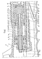
- This pruner comprises a hollow body 1 serving as a handle and on the front part or head of which is fixed, in any known manner, the fixed hook or blade 2 of the device.
- On said hook is articulated, by means of an axis 3, the movable blade 4 comprising an extension or lever 4a articulated at one end of a pair of rods 5, the other end of which is articulated in a yoke 6
- This yoke is rigidly fixed, for example by screwing, on the front end of the rod 7 of a piston. 8 advantageously formed in one piece with the latter and housed with a sealed sliding ability, in the recess of the body 1 and, more precisely, in a bore formed in the front half portion of the latter.
- This piston has two opposite working faces having, preferably, uneven surfaces, ie a large front face f1 and a small rear face f2.
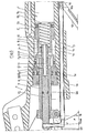
- the main piston 8 is rigidly secured, by means of a reamed spacer rod 9 disposed opposite the drive rod 7, of a secondary piston 10 provided with at least one peripheral seal and housed, with a sealed sliding ability, in a bore 1b formed in the rear half-part of the body recess, in the extension of the bore 1a and having a diameter less than the latter.
- the assembly 7-8-9-10 advantageously consists of a single piece.
- the face f3 of the secondary piston 10 disposed opposite the face f2 of the main piston 8 has a smaller surface than that of the latter.
- the pistons 8 and 10 define an annular chamber A surrounding the spacer rod 9.
- the rod 7 of the piston 8 slides, in leaktight manner, in a guide 11 consisting of at least one ring fixed, preferably in a removable manner, for example by means of a metal rod, in the front part of the recess of the body. 1.
- This guide is provided with at least one peripheral seal.
- the internal face of the guide 11 and the front face f1 of the piston 8 define an annular chamber B surrounding the rod 7.
- a distributor drawer 12 is mounted, with an axial sliding ability in the rod 7-piston 8 and rod-spacer 9 assembly.
- a compression spring 13 The latter is, for example, wedged, on the other hand a first ring 14 installed on the periphery of the rear end of said drawer and, on the other hand, against a second ring 15 mounted in the vicinity of the rear end of the bore of the rod-spacer 9- secondary piston 10 assembly.
- the spring 13 therefore tends to push the drawer 12 forward continuously relative to the assembly 7-8-9-10.
- the front end of the slide 12 is connected to the folded end 16a of an operating rod 16 housed with a sliding latitude in a longitudinal bore 1 c formed in the body 1, below the bore 1a.
- the rear end of the rod is threaded and has a slot 16b.
- This nut is immobilized in rotation by two appendages 1 that has 1 a rear part of the body 1, in the extension of the bore 1 c, and between which it can slide axially.
- This nut makes it possible to adjust 1 position, relative to the rod 16, of the articulation axis 18 passing through the slot 16b, of one of the ends of an operating rod 19 also articulated, by its opposite end, by means of a pin 20, on the rear part of a control lever or trigger 21.
- the latter is also articulated, by its front end, on axis 3.
- the articulation of the trigger 21 on the axis 3 of the movable blade and its orientation from front to rear provides better grip for users, taking into account the habit of using traditional mechanical secateurs .
- a safety ring 22 articulated on the rear part of the body 1 keeps the trigger 21 in the closed position outside the periods of use of the pruning shears.
- a housing is provided for the removable connection of the pruning shears to the device for coupling the coaxial supply and return hose 24, one of which brings the hydraulic fluid under pressure coming from a source of pressurized hydraulic fluid (pump, hydraulic circuit of a tractor, self-propelled platform or other vehicles, hydraulic group adaptable to tiller, etc.), while the other ensures the return of said fluid to said source ;
- a coupling device advantageously being of the type described in European Patent Application No. 79430005.3 (published under the number 0004249).
- the housing arranged at the rear part of the body for the junction of said coupling device comprises two coaxial cylindrical chambers, that is a first chamber C of reduced diameter intended for the sealed insertion of the internal connection integral with the end of the internal flexible 23, and a chamber D, of larger diameter, arranged after the previous one and allowing the sealed engagement of the external connection subject to the end of the external hose 24.
- a channel E formed in the body 1 establishes constant communication between the chamber C of arrival of the hydraulic fluid under pressure and the chamber A delimited by the pistons 8 and 10.
- One or more transverse bores 25 formed in the bottom of an annular groove which is provided with the slide 12, in front of the groove G1, and opening out near the bottom of the bore H allow effective drainage, towards the return, of oil which could seep out of chamber B and escape towards the front of the appliance.
- a seal 26 is inserted into an annular groove that said drawer has in its anterior portion, in front of the hole (s) 25.
- the drawer advances again under the spring thrust, putting the orifices F and the holes G in communication, which causes a new advance of the piston, and so on until complete opening of the blades if no retentive action is exerted trigger 21.
- chamber B communicates with the return by the passage FGH-1-JKD, while the drawer closes the orifices L of the LMN passage for communication between said chamber and chamber A under pressure which is thus closed.
- the drawer 12 When the trigger 21 is pressed, the drawer 12 is caused to recoil by means of the connecting rod 19 and the operating rod 16.
- the drawer slides in the assembly 7-8-9 and, at first , it closes the exhaust ports F, so that the chamber B is no longer in relation to the return.
- the drawer opens the orifices L by putting the latter in relation to the groove M, which establishes a communication between the chambers A and B by the passage L-M-N.
- chamber B causes the set 7-8-9-10 to recede, taking into account the fact that the surface f1 of the piston 8 is larger than its opposite surface f2, this difference in section being increased mented by the surface f3 of the piston 10.
- the assembly 7-8-9-10 which slides on the slide, puts an end to the communication between the orifices L and the annular groove M, so that the chamber B n being more pressurized, said assembly stops.
- the continuation of the closing movement of the trigger re-establishes the communication between said orifices and said groove, which brings about a further retreat of the assembly 7-8-9-10, and so on until the blades are completely closed if one continues to press said trigger until the end of its closing stroke.
- the closing of the blades takes place smoothly taking into account the small amplitude of the alternating and repeated movements of the drawer 12 and of the assembly 7-8-9-10 and the very short time in which they 'accomplish.
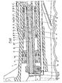
- the rear end of the spring 13 is not wedged against a ring, but against a plug 15 'screwed into the rear part of the piston 10' and sealing the bore in which is installed said spring.
- the movable blade stops in any intermediate position between closing and opening is obtained by retaining the trigger so as to immobilize the drawer 12 '.
- the assembly 7'-8'-9'-10 ' stops as soon as the inlet of the channels P is closed by the shoulder 12a' of the slide maintained in stationary state, the chamber B n ' being more pressurized, but the oil contained in this chamber being unable to escape towards the return prevents any forward movement of said assembly.
- the blades are closed in a similar fashion.
- the pistons 8 'and 10' are set at the end of the front stroke, the chamber B communicates with the return by the passage PQ-0-JKD, while the shoulder 12a 'of the drawer 12' placed between the holes R and the channels P prohibits any relationship between said chamber and chamber A under pressure.
- the shoulder 12a ′ closes the communication between the channels P and O, so that the chamber B is no longer in relation to the return.
- the shoulder 12a ′ opens the channels P by putting them in contact with the groove S, which establishes a communication between the chambers A and B by the passage R-S-P.
- chamber B causes the set 7'-8'-9'-10 'to slide back, which slides on the slide 12' taking into account that the surface f1 'of the piston 8' is larger than its surface opposite f2 ', this difference in section being increased by the working surface f3' of the piston 10 '.
- the continuation of the trigger closing movement re-establishes the communication between the holes R and the channels P, via the groove S, which causes a further decline of the assembly 7'-8'-9'-10 ', and so on until the blades are completely closed if pressure is maintained on said trigger until its closing movement has ended.
- the position of the blades is also completely subject to that of the trigger or operating lever 21.
- the bore H 'formed in the rear part of the drawer and in the bottom of which opens at least one transverse bore 25', is used only for draining the oil.
Landscapes
- Life Sciences & Earth Sciences (AREA)
- Biodiversity & Conservation Biology (AREA)
- Ecology (AREA)
- Forests & Forestry (AREA)
- Environmental Sciences (AREA)
- Scissors And Nippers (AREA)
- Shovels (AREA)
- Soil Working Implements (AREA)
Priority Applications (1)
| Application Number | Priority Date | Filing Date | Title |
|---|---|---|---|
| AT80430023T ATE12019T1 (de) | 1979-11-13 | 1980-11-12 | Baumschere mit linearer hydraulischer unterstuetzung. |
Applications Claiming Priority (2)
| Application Number | Priority Date | Filing Date | Title |
|---|---|---|---|
| FR7928269 | 1979-11-13 | ||
| FR7928269A FR2469112A1 (fr) | 1979-11-13 | 1979-11-13 | Secateur hydraulique a asservissement en position |
Publications (3)
| Publication Number | Publication Date |
|---|---|
| EP0028997A2 EP0028997A2 (fr) | 1981-05-20 |
| EP0028997A3 EP0028997A3 (en) | 1981-05-27 |
| EP0028997B1 true EP0028997B1 (fr) | 1985-03-06 |
Family
ID=9231757
Family Applications (1)
| Application Number | Title | Priority Date | Filing Date |
|---|---|---|---|
| EP80430023A Expired EP0028997B1 (fr) | 1979-11-13 | 1980-11-12 | Sécateur hydraulique à asservissement en position |
Country Status (6)
| Country | Link |
|---|---|
| US (1) | US4359821A (Direct) |
| EP (1) | EP0028997B1 (Direct) |
| AT (1) | ATE12019T1 (Direct) |
| DE (1) | DE3070257D1 (Direct) |
| ES (1) | ES496698A0 (Direct) |
| FR (1) | FR2469112A1 (Direct) |
Cited By (1)
| Publication number | Priority date | Publication date | Assignee | Title |
|---|---|---|---|---|
| WO2012045332A1 (de) * | 2010-10-04 | 2012-04-12 | Gardena Manufacturing Gmbh | Handbetätigte gartenschere |
Families Citing this family (30)
| Publication number | Priority date | Publication date | Assignee | Title |
|---|---|---|---|---|
| US5185932A (en) * | 1982-06-03 | 1993-02-16 | Caines R Scott | Robotic fluid-actuated muscle analogue tree trimmer |
| US4734983A (en) * | 1986-09-04 | 1988-04-05 | Brick Francis M | Cutting tool having single moving blade |
| FR2614568B1 (fr) * | 1987-04-28 | 1989-07-28 | Pellenc & Motte | Outil electrique portable a asservissement en position |
| DE10216213A1 (de) * | 2002-04-10 | 2003-10-23 | Klauke Gmbh Gustav | Elektrohydraulisches Verpressgerät und Verfahren zum Betreiben desselben |
| US4949461A (en) * | 1989-03-01 | 1990-08-21 | Merwe Jacobus C V D | Dual control handle for pneumatic tree trimmer |
| US4967474A (en) * | 1990-03-26 | 1990-11-06 | Wells Andrew J | Hand-held power-operated shears |
| US5070616A (en) * | 1991-04-22 | 1991-12-10 | Chen Chin L | Hydraulic type pipe cutter |
| DE4212725C2 (de) * | 1992-04-16 | 1995-04-13 | H & K Gmbh Sondermaschinen Und | Hydraulisch betriebene Baum- und Rebenschere |
| US5375330A (en) * | 1993-10-06 | 1994-12-27 | Bettcher Industries, Inc. | Hand held power operated shears |
| US5950313A (en) | 1993-10-06 | 1999-09-14 | Bettcher Industries, Inc. | Blades for hand held power operated shears |
| DE4414967C2 (de) * | 1994-04-28 | 1997-07-17 | Weidmueller Interface | Servozange |
| USD389385S (en) | 1995-12-12 | 1998-01-20 | Bettcher Industries, Inc. | Handle for power shears |
| USD397923S (en) | 1995-12-12 | 1998-09-08 | Bettcher Industries, Inc. | Scissor blade yoke for power shears |
| DE19616948C1 (de) * | 1996-04-27 | 1997-11-27 | Wagner Gmbh J | Schneidwerkzeug, insbesondere Astschere |
| DE19616949C2 (de) * | 1996-04-27 | 1998-04-09 | Wagner Gmbh J | Elektromotrisch angetriebenes Schneidwerkzeug, insbesondere Astschere |
| ES2145674B1 (es) * | 1997-05-21 | 2001-02-16 | Olmedilla Alfonso Bedmar | Herramienta portatil manual, que realiza cortes de ramas o similares, con diferentes angulos y alturas variables. |
| US5918370A (en) * | 1997-10-09 | 1999-07-06 | Jarvis Products Corporation | Hand held power assisted shears |
| USD416567S (en) | 1998-07-29 | 1999-11-16 | Rescue Technology, Inc. | Cutting blade |
| USD413241S (en) | 1998-11-19 | 1999-08-31 | Tsui-Chen Lai | Power shears |
| US6662452B2 (en) | 2002-04-22 | 2003-12-16 | Bettcher Industries, Inc. | Power operated rotary knife |
| FI117087B (fi) * | 2004-02-27 | 2006-06-15 | Fiskars Consumer Oy Ab | Oksasakset tai muut vastaavat leikkurit |
| FR2867408B1 (fr) * | 2004-03-11 | 2006-05-19 | Infaco | Dispositif de couple electroniquement asservi. |
| US7757442B2 (en) * | 2004-11-04 | 2010-07-20 | Rite-Hite Holding Corporation | Flexible structures for use with dock seals and shelters |
| US7464578B2 (en) | 2005-06-03 | 2008-12-16 | Fci Americas Technology, Inc. | Hand-held, portable, battery-powered hydraulic tool |
| US20080010837A1 (en) * | 2006-07-12 | 2008-01-17 | William Weissenborn | Fluid-driven cutting device |
| KR100812711B1 (ko) | 2006-11-07 | 2008-03-12 | 상지대학교산학협력단 | 유압식 전동가위장치 |
| FR2935106B1 (fr) * | 2008-08-22 | 2010-09-17 | Pellenc Sa | Outil electroportatif a commande par gachette |
| USD657220S1 (en) * | 2010-10-13 | 2012-04-10 | Izumi Products Company | Electric cable cutter |
| USD657221S1 (en) * | 2010-10-13 | 2012-04-10 | Izumi Products Company | Electric cable cutter |
| US20240268275A1 (en) * | 2023-02-09 | 2024-08-15 | Fiskars Finland Oy Ab | Adjustable separation sheers |
Family Cites Families (4)
| Publication number | Priority date | Publication date | Assignee | Title |
|---|---|---|---|---|
| US2714250A (en) * | 1954-09-14 | 1955-08-02 | Arthur B Twedt | Hydraulic pruning and cutting tool |
| FR2188936B3 (Direct) * | 1972-06-20 | 1975-08-08 | Lavijerie Jacqu5S | |
| FR2367422A2 (fr) * | 1975-12-24 | 1978-05-12 | Pellenc Roger | Secateur hydraulique |
| US4206603A (en) * | 1977-07-13 | 1980-06-10 | Dan Mekler | Single hand operated tool |
-
1979
- 1979-11-13 FR FR7928269A patent/FR2469112A1/fr active Granted
-
1980
- 1980-11-06 US US06/204,795 patent/US4359821A/en not_active Expired - Lifetime
- 1980-11-10 ES ES496698A patent/ES496698A0/es active Granted
- 1980-11-12 DE DE8080430023T patent/DE3070257D1/de not_active Expired
- 1980-11-12 AT AT80430023T patent/ATE12019T1/de not_active IP Right Cessation
- 1980-11-12 EP EP80430023A patent/EP0028997B1/fr not_active Expired
Cited By (2)
| Publication number | Priority date | Publication date | Assignee | Title |
|---|---|---|---|---|
| WO2012045332A1 (de) * | 2010-10-04 | 2012-04-12 | Gardena Manufacturing Gmbh | Handbetätigte gartenschere |
| EP3305061A1 (de) * | 2010-10-04 | 2018-04-11 | Husqvarna AB | Handbetätigte gartenschere |
Also Published As
| Publication number | Publication date |
|---|---|
| FR2469112A1 (fr) | 1981-05-22 |
| DE3070257D1 (en) | 1985-04-11 |
| FR2469112B1 (Direct) | 1983-07-22 |
| ATE12019T1 (de) | 1985-03-15 |
| US4359821A (en) | 1982-11-23 |
| EP0028997A2 (fr) | 1981-05-20 |
| ES8201396A1 (es) | 1981-12-16 |
| EP0028997A3 (en) | 1981-05-27 |
| ES496698A0 (es) | 1981-12-16 |
Similar Documents
| Publication | Publication Date | Title |
|---|---|---|
| EP0028997B1 (fr) | Sécateur hydraulique à asservissement en position | |
| EP0805278B1 (fr) | Dispositif de vérin pneumatique | |
| FR3040120A3 (fr) | Dispositif secateur commutable entre differents modes de fonctionnement | |
| EP0229800B1 (fr) | Dispositif de coupe et de traitememt simultanes d'une tige de plante | |
| FR2540959A1 (fr) | Dispositif distributeur de fluide, notamment pour telecommande | |
| EP0362038A1 (fr) | Dispositif de commande pour ressort à gaz blocable | |
| EP0109912B1 (fr) | Outils hydrauliques portatifs, par exemple sécateurs hydrauliques, et procédé de rappel du piston de leur vérin | |
| EP1063018B1 (fr) | Pistolet automatique à membrane pour la pulvérisation d'un produit | |
| EP0013656B1 (fr) | Sécateur pneumatique à double effet | |
| CA2547312A1 (fr) | Dispositif pneumatique autonome pour actionner un outil opere par deplacement d'un organe d'actionnement | |
| FR2772585A1 (fr) | Bras support articule notamment pour dispositifs de nettoyage | |
| EP0042312A1 (fr) | Dispositif d'insémination artificielle pour l'aviculture | |
| FR2509833A1 (fr) | Dispositif de pilotage de soupape de surete | |
| FR2517171A1 (fr) | Secateur pneumatique | |
| EP0153253B1 (fr) | Distributeur hydraulique haute pression à clapet de décharge piloté mécaniquement | |
| FR2589033A1 (fr) | Perfectionnement au dispositif de controle automatique de position de l'outil interceps | |
| EP1223840B1 (fr) | Cafetiere espresso equipee d'un systeme de purge du bloc thermique | |
| FR2702395A1 (fr) | Support pour un dispositif de pulvérisation d'un mélange d'eau et d'air sous pression. | |
| FR2654793A3 (fr) | Dispositif de commande d'une boite de changement de vitesses d'un vehicule tel qu'en particulier un tracteur agricole. | |
| FR2754000A1 (fr) | Dispositif de commande hydraulique du verin de levage d'un bras de chargeur agricole | |
| FR3111090A1 (fr) | Couteau comprenant des moyens de reglage du centre de gravite et un organe de commande accessible depuis l’exterieur du manche | |
| CA1145221A (fr) | Dispositif d'injection, notamment pour substances medicamenteuses | |
| FR2561545A1 (fr) | Lance, notamment pour la lutte contre les incendies | |
| FR2563688A1 (fr) | Secateur cueille fleur | |
| WO1980001539A1 (fr) | Dispositif d'injection sans aiguille de substances medicamenteuses liquides |
Legal Events
| Date | Code | Title | Description |
|---|---|---|---|
| ITCL | It: translation for ep claims filed |
Representative=s name: DR. ING. A. RACHELI & C. |
|
| PUAI | Public reference made under article 153(3) epc to a published international application that has entered the european phase |
Free format text: ORIGINAL CODE: 0009012 |
|
| PUAL | Search report despatched |
Free format text: ORIGINAL CODE: 0009013 |
|
| AK | Designated contracting states |
Designated state(s): AT BE CH DE GB IT NL SE |
|
| AK | Designated contracting states |
Designated state(s): AT BE CH DE GB IT NL SE |
|
| 17P | Request for examination filed |
Effective date: 19811015 |
|
| ITF | It: translation for a ep patent filed | ||
| GRAA | (expected) grant |
Free format text: ORIGINAL CODE: 0009210 |
|
| AK | Designated contracting states |
Designated state(s): AT BE CH DE GB IT LI NL SE |
|
| PG25 | Lapsed in a contracting state [announced via postgrant information from national office to epo] |
Ref country code: SE Effective date: 19850306 Ref country code: NL Effective date: 19850306 Ref country code: AT Effective date: 19850306 |
|
| REF | Corresponds to: |
Ref document number: 12019 Country of ref document: AT Date of ref document: 19850315 Kind code of ref document: T |
|
| REF | Corresponds to: |
Ref document number: 3070257 Country of ref document: DE Date of ref document: 19850411 |
|
| NLV1 | Nl: lapsed or annulled due to failure to fulfill the requirements of art. 29p and 29m of the patents act | ||
| PG25 | Lapsed in a contracting state [announced via postgrant information from national office to epo] |
Ref country code: LI Effective date: 19851130 Ref country code: CH Effective date: 19851130 Ref country code: BE Effective date: 19851130 |
|
| PLBE | No opposition filed within time limit |
Free format text: ORIGINAL CODE: 0009261 |
|
| STAA | Information on the status of an ep patent application or granted ep patent |
Free format text: STATUS: NO OPPOSITION FILED WITHIN TIME LIMIT |
|
| 26N | No opposition filed | ||
| BERE | Be: lapsed |
Owner name: ETS PELLENC ET MOTTE S.A.R.L Effective date: 19851130 |
|
| GBPC | Gb: european patent ceased through non-payment of renewal fee | ||
| REG | Reference to a national code |
Ref country code: CH Ref legal event code: PL |
|
| PG25 | Lapsed in a contracting state [announced via postgrant information from national office to epo] |
Ref country code: GB Effective date: 19881118 |
|
| PG25 | Lapsed in a contracting state [announced via postgrant information from national office to epo] |
Ref country code: DE Effective date: 19890801 |