EP0022953B1 - Elektromagnetisches Relais - Google Patents
Elektromagnetisches Relais Download PDFInfo
- Publication number
- EP0022953B1 EP0022953B1 EP80103714A EP80103714A EP0022953B1 EP 0022953 B1 EP0022953 B1 EP 0022953B1 EP 80103714 A EP80103714 A EP 80103714A EP 80103714 A EP80103714 A EP 80103714A EP 0022953 B1 EP0022953 B1 EP 0022953B1
- Authority
- EP
- European Patent Office
- Prior art keywords
- contact
- armature
- spring
- electromagnetic relay
- actuating
- Prior art date
- Legal status (The legal status is an assumption and is not a legal conclusion. Google has not performed a legal analysis and makes no representation as to the accuracy of the status listed.)
- Expired
Links
- 230000009471 action Effects 0.000 claims description 2
- 229920002994 synthetic fiber Polymers 0.000 claims 3
- 230000005284 excitation Effects 0.000 abstract description 2
- 230000004907 flux Effects 0.000 abstract 1
- 238000010276 construction Methods 0.000 description 5
- 238000004804 winding Methods 0.000 description 5
- 239000011810 insulating material Substances 0.000 description 4
- 238000004519 manufacturing process Methods 0.000 description 3
- 238000000034 method Methods 0.000 description 3
- 238000005192 partition Methods 0.000 description 3
- 230000008569 process Effects 0.000 description 3
- 238000003466 welding Methods 0.000 description 3
- 238000005452 bending Methods 0.000 description 2
- 208000034656 Contusions Diseases 0.000 description 1
- 230000008859 change Effects 0.000 description 1
- 244000145845 chattering Species 0.000 description 1
- 238000004140 cleaning Methods 0.000 description 1
- 239000012141 concentrate Substances 0.000 description 1
- 230000007547 defect Effects 0.000 description 1
- 230000000694 effects Effects 0.000 description 1
- 210000003746 feather Anatomy 0.000 description 1
- 210000003608 fece Anatomy 0.000 description 1
- 238000003780 insertion Methods 0.000 description 1
- 230000037431 insertion Effects 0.000 description 1
- 239000010871 livestock manure Substances 0.000 description 1
- 238000003825 pressing Methods 0.000 description 1
- 230000009467 reduction Effects 0.000 description 1
- 230000004044 response Effects 0.000 description 1
- 230000035945 sensitivity Effects 0.000 description 1
- 238000005507 spraying Methods 0.000 description 1
- 229920003002 synthetic resin Polymers 0.000 description 1
- 239000000057 synthetic resin Substances 0.000 description 1
Images

Classifications
-
- H—ELECTRICITY
- H01—ELECTRIC ELEMENTS
- H01H—ELECTRIC SWITCHES; RELAYS; SELECTORS; EMERGENCY PROTECTIVE DEVICES
- H01H50/00—Details of electromagnetic relays
- H01H50/54—Contact arrangements
- H01H50/56—Contact spring sets
-
- H—ELECTRICITY
- H01—ELECTRIC ELEMENTS
- H01H—ELECTRIC SWITCHES; RELAYS; SELECTORS; EMERGENCY PROTECTIVE DEVICES
- H01H51/00—Electromagnetic relays
- H01H51/22—Polarised relays
- H01H51/2227—Polarised relays in which the movable part comprises at least one permanent magnet, sandwiched between pole-plates, each forming an active air-gap with parts of the stationary magnetic circuit
-
- H—ELECTRICITY
- H01—ELECTRIC ELEMENTS
- H01H—ELECTRIC SWITCHES; RELAYS; SELECTORS; EMERGENCY PROTECTIVE DEVICES
- H01H3/00—Mechanisms for operating contacts
- H01H3/001—Means for preventing or breaking contact-welding
Definitions
- the invention relates to an electromagnetic relay with an armature block, which contains a pair of armature bridges with an interposed permanent magnet, which magnetizes the armature bridges in opposite directions, with a substantially U-shaped yoke with projecting ends, each in an air gap between the opposite ends the armature webs are arranged, which extend beyond the sections of the armature webs that are in contact with the permanent magnet, with a coil that can be connected to a control source for excitation of the relay and with a bearing device for the armature block, such that the armature block can be selectively in the direction of the projecting ends of the yoke is movable.
- a relay of this type has the structure shown in Fig. 17 and is e.g. described in DE-B2-2 454 967. It has an armature block h with a pair of armature webs e, d which are arranged parallel to one another, in front of and behind projecting ends c of a yoke b which carries a coil winding a.
- a permanent magnet f is arranged between the anchor webs e, d.
- the anchor block is essentially journal-supported in the center of the anchor webs e, d by means of a round axis i in a bore j.
- such an anchor block is generally carried out in such a way that the permanent magnet is arranged in a one-piece pressed part in the middle between parts which serve as anchor webs e, d.
- the influence of the heat causes a change in the distance between the anchor bars, which changes the path of the anchor bars relative to the yoke.
- the actuating part for the contact spring is molded onto the armature block. This design measure is chosen for this relay because large contact forces and a high degree of self-cleaning effect are required to achieve high switching loads and high resistance to contact welding.
- one of the contacts makes contact by deflecting the spring, while the other contact is forcibly lifted off.
- the load capacity of the contacts is unequal, which is due to the difference in the force stored in the springs from the permanent magnetic attraction. Therefore, it is difficult to ensure a sufficiently high sensitivity with such a construction.
- the object of the invention is to provide a relay of the type mentioned, which is simple in construction and easy to manufacture, which is still free of fluctuations in the armature air gap and the air gap between the yoke and both armature webs, the safe contact opening and closing granted, so that it has stable switching behavior, and which also has a relatively large contact opening with respect to the armature opening.
- the bearing device has a resilient arm which extends away from the anchor block perpendicular to its axis of rotation and is attached to its more distant end facing away from the anchor.
- the frame-like part which is a pair of Anchor bars and a permanent magnet in the middle, as well as the flexible arm that can bend perpendicular to the direction of rotation of the anchor bars, create a unit through which the relay can be set up in a particularly simple manner.
- the flexible arm is fixed in a bearing of the relay body. This arrangement requires neither a journal nor a hole in the anchor block and therefore does not require any particular precision in order to achieve sufficient accuracy for the axis of rotation.
- an advantageous embodiment of the invention can consist in the shape of one of the anchor webs, the actuating pieces and the flexible arm, which ensures the rotatable mounting of the anchor, in order to ensure an exact anchor air gap.
- cranks are provided on the surfaces of the two actuating pieces, through which the contact springs are guided such that the inside of each crank encompasses the contact spring in a gap, so that both resilient contact and forced contact opening are ensured.
- one of the two contacts is attached to a contact spring which is forcibly opened and which is provided with an auxiliary spring.
- the auxiliary spring is designed so that it is supported on a fixed part immediately before lifting.
- 1 denotes a housing which consists of a base plate 2 made of insulating material or plastic and a housing cap 3.
- 4 with a bobbin is designated, which has a winding area 5 and two flanges 6.
- the winding area 5 of the bobbin 4 is provided with a continuous opening 7, in which a yoke 8 is arranged such that ends 8a protrude upward on the opposite flanges 6.
- the coil winding C, the coil body 4 and the yoke 8 together form the electromagnetic circuit M.
- One pole face is wider than the other.
- a plate-shaped or cuboid permanent magnet 10 is arranged between the anchor webs 9.
- An insulating frame 11 holds the anchor bars 9 and the permanent magnet 10 together. It has on the upper side a wall 12 along which one of the anchor webs extends, a pair of posts 13 through which one anchor web is passed, and a horizontal wall 14 which, together with the post 13, has a cavity for receiving the permanent magnet 10 forms. A projection 14a on the horizontal wall 14 serves to position the permanent magnet, receives the other armature web and encloses it with the exception of the pole faces 9a, 9b. All walls are integrally connected to the insulating frame 11.
- One anchor web 9, which penetrates the posts 13, is designed as a thin plate in order to facilitate insertion into the mold and, at the same time, embedding.
- the insulating frame 11 also has a resilient arm 15 projecting in the middle, which can bend in the direction T perpendicular to the direction of rotation R of the anchor bars 9 (FIG. 12).
- the insulating frame 11 including the flexible arm 15 is formed from a plastic with high resistance to arcing.
- the arm 15 is formed from a metallic leaf spring embedded in the insulating frame 11.
- the arm 15 can also be provided on both sides, as shown in FIGS. 10 and 11. Relatively stiff synthetic resin can also be used, as long as sufficient flexibility can be ensured by the thickness or shape of the arm 15.
- the two anchor bars 9, the permanent magnet 10, the insulating frame 11 and the flexible arm 15 together form the anchor block G.
- the base plate 2 is provided with a bearing block 16.
- the arm 15 is tapered in cross section in the area of its connection 15b in the vicinity of the insulating frame 11 and widened at its front end 15a in such a way that an air gap 16a arises in the area of the connection 15b and that its front, widened end 15a against a pair of firmly anchored side walls 17.
- movable contact springs are designated, which are arranged on both sides of the flexible arm 1 5. Each of these feathers lies on the upper pan manure 12 of the insulating frame 11 of the armature block opposite and is provided at its front end with a contact 19. Each contact spring 18 is also fastened to an L-shaped base part 20a of a contact connection 20 with an L-shaped foot part 18a. The movable contact spring 18 engages the inner surface 22 of a bend of an operating part 21 for the purpose of a forced contact opening. 23 is a further contact connection which carries a fixed contact 24. The two contacts 19 and 24 form a contact arrangement S.
- the base plate 2 has an upright partition 25 which is arranged as an arc protection between this contact arrangement S on the one hand and the part M of the electromagnetic circuit and the armature block G on the other.
- the partition wall 25 is integrally formed on the side walls 17 of the bearing block 16.
- a connecting pin 26 for the coil winding C is L-shaped, the horizontal portion 26a of which is passed through the flange 6 of the coil body 4. The contact connections 20, 23 and the connection pin 26 penetrate the base plate 2.
- the one of two contacts which is denoted by 27, is closed by bending the contact spring and stands out from the fixed contact 28 serving as an abutment when there is no force from the armature 30.
- the other contact with the contact spring 29 is forcibly opened and then closed when no force is exerted by the armature.
- the contact spring 29 of the contact which is forcibly opened carries the movable contact 31 on the side facing the armature 30 and on the other side an auxiliary spring 32 which is supported on it and which is also fastened to the same contact connection 33.
- the free end of the auxiliary spring 32 is not always supported on the contact spring 29, but only when the contact spring 29 is lifted off the fixed contact 28.
- the spring force of the contact spring 29 is increased by the force of the auxiliary spring 32 at this time.
- the resulting spring force from the deflection upon contact, the forced contact opening and the auxiliary spring at the end of the armature movement on the side on which the contact is opened takes on an increased value until the spring force on the side at the contact opening is equal is the value of the spring force on the side where the contact is closed. In this way, the resulting spring force is adjusted to the actuating force of the armature.
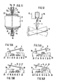
- Fig. 13 (where Fig. 13A represents the rest position of the relay) shows an arrangement with a work and a break contact, in which the armature block G is moved when the coil is excited over the flexible arm 15, whereby the contact arrangements S on both sides can be opened and closed alternately (Figs. 13A, 13B).
- FIG. 14 which shows another arrangement with two working contacts (with Fig. 14A showing the rest position of the relay), the rotation of the armature block G causes the two contact arrangements on both sides to open or close simultaneously.
- the arrangement of FIG. 13 corresponds to the construction shown in FIG. 7 and the arrangement according to FIG. 14 corresponds to that shown in FIG. 9.
- the relationship between the anchor block G and the elastic arm 15 is that the arm 15 is bent in a direction T perpendicular to the axis of rotation of the anchor block G in response to its rotation, as shown in FIG. 12. If the axis of rotation is displaced from the normal position, a subsequent movement to the right or left or forwards or backwards occurs within the area of the deflection to compensate for the offset, thereby compensating for the problem of chattering or excessive play on the axis of rotation.
- the electromagnetic relay according to the invention is designed such that the insulating frame 11, which carries the anchor bars 9 and the permanent magnet 10, is formed in one piece with the elastic arm 15, which can bend perpendicularly to the direction of the axis of rotation of the anchor bars 9 and from the bearing block 16 of the base plate 2 is held securely, any offset due to a deflection of the elastic arm 15 is made ineffective by said subsequent movement.
- This arrangement makes it unnecessary to devote great care to the centering that was required with conventional journal bearings.
- the armature block G is also a unit which comprises the armature webs 9, the permanent magnet 10 and an insulating frame 11, the final assembly compared to the known relays according to the prior art, in which only one tail after the other can be installed in the housing , made much more efficient.
- the electromagnetic relay according to the invention is further characterized in that the upright partition 25 is provided in its base plate 2 in order to provide protection against arcing between the contacts. Furthermore, the common contact spring 18 is designed such that it comes into engagement with the inner surface of the offset of the actuating part 21.
- the insulating frame 11, which carries the anchor bars 9 and the permanent magnet 1 O, is on its top with the wall 12, along which one of the anchor bars is arranged, the pair of posts 13, which an anchor bar passes, and the horizontal wall 14, which together with said posts 13 forms a cavity for receiving and securing the permanent magnet.
- the wall projection 14a which extends from the horizontal wall and together with this forms a positioning segment for the permanent magnet, which is adapted to and covers the other armature web 9, the pole faces 9a and 9b of which remain uncovered alone. All the walls mentioned are integrally connected to the frame part.
- one of the contact springs is provided with a contact that springs through when contact is made, while the other contact spring carries a contact that is forced to open.
- the former Contact spring is provided with an auxiliary spring, which is supported on the surface of the contact spring facing away from the moving contact, whereby the advantages mentioned are achieved.
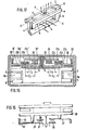
- the 16 also shows a rotary anchor in which an anchor provided with permanent magnets is mounted on one side on a flexible arm 15 in a bearing block 16.
- the insulating material sheath also fixes in the armature at least one permanent magnet (not shown) and armature webs 9 which cooperate with the yoke ends 8a of the coil core.
- the actuating pieces 21 a, 21 b and 21 a ', 21 b' shown in section are connected to one another at their top, that is to say they grip around the contact springs 18 and 18 '.
- the right contact point 19, 24 is closed, the left contact point 19 ', 24' is open.
- the crowned actuating piece 21 b presses against the contact spring 18, while the opposite actuating piece 21 a is lifted off the latter.
- the contact spring 18 experiences considerable deflection.
- the contact opening at the left contact point 19 ', 24' takes place through the action of the actuating piece 21a 'on the contact spring 18', the actuating piece 21 b 'being lifted off the contact spring.
- the contact-near section 21c, 21c 'of the actuating piece 21a, 21a' engages with the contact spring 18, 18 ', so that only the short resilient length L 3 , L 3 ' is effective up to the contact point .
- the contact point on the contact spring moves with increasing opening of the contact point 19 ', 24', since the surface of the actuating piece 21 a 'facing the contact spring 18' runs parallel to the longitudinal axis of the armature 8, from the contact-less to the non-contact section 21 d 'of the actuating piece 21 a '.
- the permanent magnetic attraction force can also be stored well in the contact springs 18, 18 '. Due to the slight deflection of the contact springs 18, 18 'at the contact opening, however, in the case of contact welding, the welded contact is either torn open and the other is properly operated - or, if the welding point cannot be broken, the other contact is also no longer operated.
Landscapes
- Physics & Mathematics (AREA)
- Electromagnetism (AREA)
- Electromagnets (AREA)
- Surgical Instruments (AREA)
- Valve Device For Special Equipments (AREA)
- Cookers (AREA)
Description
- Die Erfindung betrifft ein elektromagnetisches Relais mit einem Ankerblock, der ein Paar von Ankerstegen mit einem dazwischen gelagerten Dauermagneten enthält, welcher die Ankerstege entgegengesetzt aufmagnetisiert, mit einem im wesentlichen U-förmigen Joch mit vorspringenden Enden, die jeweils in einem Luftspalt zwischen den einander gegenüberliegenden Enden der Ankerstege angeordnet sind, die sich über die mit dem Dauermagneten in Kontakt stehenden Abschnitte der Ankerstege hinaus erstrecken, mit einer an eine Steuerquelle anschaltbaren Spule zur Erregung des Relais und mit einer Lagereinrichtung für den Ankerblock, derart, dass der Ankerblock wahlweise in Richtung auf die vorspringenden Enden des Jochs zu bewegbar ist.
- Ein Relais dieser Art hat den in Fig. 17 dagestellten Aufbau und ist z.B. in der DE-B2-2 454 967 beschrieben. Es besitzt einen Ankerblock h mit einem Paar von Ankerstegen e, d, die parallel zueinander, vor und hinter vorspringenden Enden c eines Jochs b angeordnet sind, das eine Spulenwicklung a trägt. Zwischen den Ankerstegen e, d ist ein Dauermagnet f angeordnet. Der Ankerblock ist im wesentlichen in der Mitte der Ankerstege e, d mit Hilfe einer runden Achse i in einer Bohrung j zapfengelagert.
- Der Aufbau eines Relais, bei dem die Hin- und Her-oder Drehbewegung des Ankerblocks mit einer derartigen Zapfenlagerung bewirkt wird, hat folgende Nachteile:
- (1) Die runde Achse i muss exakt am Schnittpunkt der Mittellinie X-X der Ankerstege e, d und der Mittellinie Y-Y des besagten Jochs b positioniert sein.
- Die Notwendigkeit dieser konstruktiven Massnahme besteht darin, dass sich die Ankerstege e, d an den vorspringenden Enden des Jochs b abstützen sollen. Falls die Achse i aus dem Schnittpunkt beider Achsen verrückt ist, weichen die Enden von der vorgesehenen Einstellung ab und bilden jeweils an einem Ende einen Luftspalt, während nur am anderen Ende ausreichende Anlagerung gewährleistet ist. Dies verursacht Prellungen und schlechten elektrischen Kontakt. Insgesamt erfordert es ein hohes Mass an Fertigungsgenauigkeit, die runde Lagerachse in den Schnittpunkt der beiden Achsen zu legen.
- (2) Selbstverständlich muss ausserdem zwischen Achse i und Bohrung j ein gewisses Lagerspiel vorgesehen sein, das der Spanne der Fertigungstoleranzen gerecht wird. Aber wegen dieses Lagerspiels kann es passieren, dass eines der vorspringenden Enden des Jochs von den Ankerstegen nicht berührt wird, während am anderen Ende zufriedenstellender Kontakt erfolgt. Dies wiederum führt zu instabiler Kontaktgabe. Ferner sind die dynamischen Verhältnisse dieses Magnetsystems derart, dass sich die Anlagekräfte (Anzugskräfte) an beiden Enden der Ankerstege auf eine Seite der runden Lagerachse konzentrieren, wobei die resultierende Kraft als Kontaktkraft nutzbar ist. Eine unzureichende Anlagekraft an einem Ende führt zu einer Verringerung der Kontaktkraft unter den Sollwert und verursacht letztlich eine für das elektromagnetische Relais unzureichende Schaltleistung.
- (3) In Verbindung mit Vorstehendem wird, wenn das Lagerspiel zwischen der Lagerachse und der Bohrung zu sehr verringert wird, der Reibungswiderstand so sehr erhöht, dass er von der die Drehung bewirkenden Kraft abgezogen werden muss.
- Ferner erfolgt der Aufbau eines derartigen Ankerblocks im allgemeinen derart, dass der Dauermagnet in einem einstückigen Pressteil in der Mitte zwischen Teilen angeordnet wird, die als Ankerstege e, d dienen. Nach dem Spritz- oder Pressvorgang entsteht jedoch durch den Einfluss der Wärme eine Änderung im Abstand der Ankerstege, wodurch sich der Weg der Ankerstege gegenüber dem Joch ändert.
- Ausserdem ist bei diesem bekannten Relais das Betätigungsteil für die Kontaktfeder am Ankerblock angeformt. Diese konstruktive Massnahme ist für dieses Relais gewählt, weil grosse Kontaktkräfte und ein hohes Mass an Selbstreinigungswirkung benötigt werden, um hohe Schaltlasten und hohe Beständigkeit gegen Kontaktverschweissung zu erzielen.
- Aus diesem Grunde findet bei der gewählten Kontaktbetätigung Kontaktgabe unter Durchbiegung der Kontaktfedern statt. Jedoch kann sich bei derartigen Kontaktbetätigungsteilen der Ankerblock ohne zusätzliche Vorkehrungen auch dann bewegen, wenn einer der Kontakte verschweisst ist, und ungeachtet des Defekts auch den anderen Kontakt schliessen, was im Schaltkreis weitere Probleme schaffen kann.
- Bei einem anderen elektromagnetischen Relais erfolgt bei einem der Kontakte Kontaktgabe unter Durchbiegung der Feder, während der andere Kontakt zwangsweise abgehoben wird. Hierbei besteht jedoch das Problem, dass die Belastbarkeit der Kontakte ungleich ist, was auf die Unterschiedlichkeit der in den Federn aus der dauermagnetischen Anzugskraft gespeicherten Kraft zurückzuführen ist. Deshalb ist es bei einer solchen Konstruktion schwierig, ausreichend hohe Empfindlichkeit zu gewährleisten.
- Aufgabe der Erfindung ist es nun, ein Relais der eingangs genannten Art zu schaffen, das einfach im Aufbau und problemlos herzustellen ist, das dabei trotzdem frei von Schwankungen des Ankerluftspaltes und des Luftspaltes zwischen dem Joch und beiden Ankerstegen ist, das sicheres Kontaktöffnen und -schliessen gewährt, damit stabiles Schaltverhalten aufweist, und bei dem ausserdem in bezug auf die Ankeröffnung eine relativ grosse Kontaktöffnung erfolgt.
- Erfindungsgemäss wird diese Aufgabe dadurch gelöst, dass die Lagereinrichtung einen federnden Arm besitzt, der sich vom Ankerblock weg senkrecht zu dessen Drehachse erstreckt und an seinem entfernteren, vom Anker abgewandten Ende, befestigt ist.
- Durch diese Massnahmen erhält man ein elektromagnetisches Relais, dessen Kontakte nicht zum Verschweissen neigen, das bei hoher Anzugskraft mechanischen Beanspruchungen widersteht und das sich durch hohe elektrische Spannungsfestigkeit auszeichnet.
- Durch das rahmenartige Teil, welches ein Paar von Ankerstegen und in der Mitte einen Dauermagneten aufnimmt, sowie zusätzlich den nachgiebigen Arm aufweist, der sich senkrecht zur Drehrichtung der Ankerstege biegen kann, entsteht eine Einheit, durch die das Relais auf besonders einfache Weise aufzubauen ist. Der flexible Arm ist dabei in einer Lagerung des Relais-Grundkörpers befestigt. Diese Anordnung benötigt weder Lagerzapfen noch Bohrung im Ankerblock und benötigt daher keine besondere Präzision, um ausreichende Genauigkeit für die Drehachse zu erzielen.
- Ferner kann eine vorteilhafte Ausgestaltung der Erfindung darin bestehen, einen der Ankerstege, die Betätigungsstücke und den flexiblen Arm, der die drehbare Lagerung des Ankers gewährleistet, in der Formgebung als Einheit festzulegen, um einen exakten Ankerluftspalt zu gewährleisten.
- Nach einer Weiterbildung der Erfindung sind an den Oberflächen der beiden Betätigungsstücke Kröpfungen vorgesehen, durch die die Kontaktfedem derart geführt werden, dass die Innenseite jeder Kröpfung die Kontaktfeder in einem Spalt umfasst, so dass sowohl federnde Kontaktgabe als auch zwangsweise Kontaktöffnung gewährleistet sind.
- Ferner ist nach einer weiteren Ausgestaltung der Erfindung einer der beiden Kontakte an einer zwangsweise zu öffnenden Kontaktfeder angebracht, die mit einer Hilfsfeder versehen ist. Um die Kontaktfederkraft zu vergrössern und dadurch sowohl Symmetrie in der Kraft der genannten und der gegenüberliegenden Kontaktfeder herbeizuführen als auch übereinstimmende Anzugskräfte in beiden Schaltrichtungen zu erzielen, ist die Hilfsfeder so ausgebildet, dass sie sich unmittelbar vor dem Abheben an einem feststehenden Teil abstützt.
- Die Erfindung wird im folgenden anhand der in den Zeichnungen dargestellten Ausführungsbeispiele näher beschrieben.
- Im einzelnen zeigt
- Fig. 1 eine Vorderansicht im Schnitt,
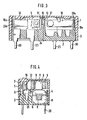
- Fig. 2 und 3 Längsschnitte gemäss den Linien A-A bzw. B-B in Fig. 1,
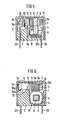
- Fig. 4 bis 6 Querschnitte gemäss den Linien C-C, D-D bzw. E-E in Fig. 1,
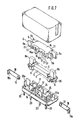
- Fig. 7 eine perspektivische Darstellung des zerlegten Relais,
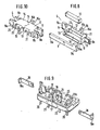
- Fig. 8 eine perspektivische Darstellung von wichtigen Einzelteilen des Relais,
- Fig. 9 und 10 perspektivische Darstellungen verschiedener Ausführungsbeispiele,
- Fig. 11 ein Schnittbild eines anderen Ausführungsbeispiels,
- Fig. 12 eine vergrösserte Darstellung, an der die Arbeitsweise des Relais erläutert wird,
- Fig. 13 und 14 Ansichten, die den Schaltvorgang erläutern,
- Fig. 15 eine schematische Darstellung eines weiteren Ausführungsbeispiels der Erfindung,
- Fig. 16 ein Ausführungsbeispiel eines Relais mit zwangsweiser Kontaktöffnung, und
- Fig. 17 ein dem Stand der Technik zuzuordnendes Relais.
- Bei dem in den Figuren dargestellten Relais ist mit 1 ein Gehäuse bezeichnet, das aus einer Grundplatte 2 aus Isolierstoff bzw. Kunststoff und einer Gehäusekappe 3 besteht. Mit 4 ist ein Spulenkörper bezeichnet, der einen Wickelbereich 5 und zwei Flansche 6 hat. Der Wickelbereich 5 des Spulenkörpers 4 ist mit einer durchgehenden Öffnung 7 versehen, in der ein Joch 8 derart angeordnet ist, dass an den gegenüberüberliegenden Flanschen 6 Enden 8a nach oben gerichtet hervorragen. Die Spulenwicklung C, der Spulenkörper 4 und das Joch 8 bilden zusammen den Elektromagnetkreis M.
- Ein Paar von Ankerstegen 9,die den vorspringenden Enden 8a jeweils zu beiden Seiten gegenüberliegen, besitzen Polflächen 9a, 9b, die den vorspringenden Enden 8a des Jochs zur Kontaktgabe angepasst sind. Dabei ist die eine Polfläche breiter als die andere. Zwischen den Ankerstegen 9 ist ein platten- bzw. quaderförmiger Dauermagnet 10 angeordnet.
- Ein Isolierstoffrahmen 11 hält die Ankerstege 9 und den Dauermagneten 10 zusammen. Er besitzt an der Oberseite eine Wandung 12, entlang der sich einer der Ankerstege erstreckt, ein Paar von Pfosten 13, durch die der eine Ankersteg hindurchgeführt ist, sowie eine horizontale Wand 14, die zusammen mit den Pfosten 13 eine Höhlung zur Aufnahme des Dauermagneten 10 bildet. Ein Vorsprung 14a an der horizontalen Wand 14 dient der Positionierung des Dauermagneten, nimmt den anderen Ankersteg auf und umschliesst ihn mit Ausnahme der Polflächen 9a, 9b. Dabei sind alle Wände einstückig mit dem Isolierstoffrahmen 11 verbunden. Der eine Ankersteg 9, der die Pfosten 13 durchdringt, ist als dünnes Plättchen ausgebildet, um das Einlegen in die Form und gleichzeitig die Einbettung zu erleichtern.
- Der Isolierstoffrahmen 11 besitzt ferner einen in der Mitte vorspringenden federnden Arm 15, der sich in der zur Drehrichtung R der Ankerstege 9 (Fig. 12) senkrechten Richtung T biegen kann. In den Figuren 1, 6, 7 und 10 ist der Isolierstoffrahmen 11 einschliesslich desflexiblen Armes 15 aus einem Kunststoff hoher Lichtbogenbeständigkeit geformt. Bei dem in Fig. 11 gezeigten Ausführungsbeispiel ist der Arm 15 aus einer in dem Isolierstoffrahmen 11 eingebetteten metallischen Blattfeder gebildet. Aus diesem Grunde wird hierfür der Begriff «Baueinheit» verwendet, weil diese, im Gegensatz zum bekannten Drehankersystem mit Zapfenlagerung, als Ganzes spielfrei arbeitet. Der Arm 15 kann ausserdem wie in Fig. 10 und 11 gezeigt, beidseitig vorgesehen sein. Auch kann relativ steifes Kunstharz verwendet werden, solange ausreichende Nachgiebigkeit durch Dicke oder Formgebung des Armes 15 gewährleistet werden kann. Die beiden Ankerstege 9, der Dauermagnet 10, der Isolierstoffrahmen 11 und der nachgiebige Arm 15 bilden zusammen den Ankerblock G.
- Die Grundplatte 2 ist mit einem Lagerblock 16 versehen. Um die Nachgiebigkeit zu erhöhen, ist der Arm 15 im Bereich seiner Anbindung 15b in der Nähe des Isolierstoffrahmens 11 in seinem Querschnitt verjüngt und an seinem vorderen Ende 15a derart verbreitert, dass ein Luftspalt 16a im Bereich der Anbindung 15b entsteht und dass sich sein vorderes, verbreitertes Ende 15a an ein Paar fest verankerter Seitenwände 17 anlegt.
- Mit 18 sind bewegliche Kontaktfedern bezeichnet, die beiderseits des nachgiebigen Armes 1 5 angeordnet sind. Jede dieser Federn liegt der oberen Wandung 12 des Isolierstoffrahmens 11 des Ankerblocks gegenüber und ist an ihrem vorderen Ende mit einem Kontakt 19 versehen. Jede Kontaktfeder 18 ist ausserdem mit einem L-förmigen Fussteil 18a an einem ebenfalls L-förmigen Basisteil 20a eines Kontaktanschlusses 20 befestigt. Die bewegliche Kontaktfeder 18 tritt mit der Innenfläche 22 einer Abkröpfung eines Betätigungsteils 21 zum Zwecke einer zwangsweisen Kontaktöffnung in Eingriff. Mit 23 ist ein weiterer Kontaktanschluss bezeichnet, der einen Festkontakt 24 trägt. Die beiden Kontakte 19 und 24 bilden eine Kontaktanordnung S.
- Die Grundplatte 2 besitzt eine aufrechte Trennwand 25, die als Lichtbogenschutz zwischen dieser Kontaktanordnung S einerseits und dem Teil M des Elektromagnetkreises und dem Ankerblock G andererseits angeordnet ist. Die Trannwand 25 ist an die Seitenwände 17 des Lagerblocks 16 angeformt. Ein Anschlussstift 26 für die Spulenwicklung C ist L-förmig ausgebildet, wobei dessen horizontaler Abschnitt 26a durch den Flansch 6 des Spulenkörpers 4hindurchgeführt ist. Die Kontaktanschlüsse 20, 23 und der Anschlussstift 26 durchsetzen die Grundplatte 2.
- Fig. 15 ist eine schematische Darstellung einer weiteren bevorzugten Ausführung der Erfindung, die eine bessere Abstimmung von Federkraft und Stellkraft gewährleistet. Dabei wird der eine von zwei Kontakten, der mit 27 bezeichnet ist, unter Durchbiegung der Kontaktfeder geschlossen und hebt sich von dem als Widerlager dienenden Festkontakt 28 ab, wenn keine Krafteinwirkung durch den Anker 30 vorliegt. Der andere Kontakt mit der Kontaktfeder 29 wird zwangsweise geöffnet und dann geschlossen, wenn keine Krafteinwirkung durch den Anker stattfindet. Die Kontaktfeder 29 des zwangsweise zu öffnenden Kontaktes trägt an der dem Anker 30 zugewandten Seite den beweglichen Kontakt 31 und an der anderen Seite eine sich an ihr abstützende Hilfsfeder 32, die auch am gleichen Kontaktanschluss 33 befestigt ist. Das freie Ende der Hilfsfeder 32 stützt sich dabei nicht immer an der Kontaktfeder 29 ab, sondern nur dann, wenn die Kontaktfeder 29 vom Festkontakt 28 abgehoben ist. Die Federkraft der Kontaktfeder 29 wird zu diesem Zeitpunkt um die Kraft der Hilfsfeder 32 vermehrt. Dabei nimmt die resultierende Federkraft aus der Durchfederung bei Kontaktgabe, der zwangsweisen Kontaktöffnung und der Hilfsfeder am Ende der Ankerbewegung an der Seite, an der der Kontakt geöffnet wird, einen erhöhten Wert an, bis die Federkraft an der Seite, an der Kontaktöffnung erfolgt, gleich dem Wert der Federkraft an der Seite ist, an der der Kontakt geschlossen wird. Auf diese Weise wird die resultierende Federkraft der Stellkraft des Ankers angeglichen.
- Im folgenden wird die Betriebsweise des erfindungsgemässen Relais beschrieben. Dabei zeigt Fig. 13 (wobei Fig. 13A die Ruhelage des Relais wiedergibt) eine Anordnung mit einem Arbeits- und einem Ruhekontakt, bei der der Ankerblock G bei Erregung der Spule über den nachgiebigen Arm 15 bewegt wird, wodurch die Kontaktanordnungen S an beiden Seiten abwechselnd geöffnet und geschlossen werden (Fig. 13A, 13B).
- In Fig. 14, die eine andere Anordnung mit zwei Arbeitskontakten zeigt (wobei Fig. 14A die Ruhelage des Relais zeigt), bewirkt die Drehung des Ankerblocks G ein gleichzeitiges Öffnen bzw. Schliessen der beiden Kontaktanordnungen an beiden Seiten. Die Anordnung von Fig. 13 entspricht der in Fig. 7 dargestellten Konstruktion und die Anordnung nach Fig. 14 entspricht der in Fig. 9 dargestellten.
- Die Beziehung zwischen dem Ankerblock G und dem elastischen Arm 15 besteht darin, dass der Arm 15 in einer Richtung T senkrecht zur Drehachse des Ankerblocks G als Reaktion auf dessen Drehung gebogen wird, wie dies in Fig. 12 gezeigt ist. Wenn die Drehachse aus der Normallage verschoben ist, entsteht eine Folgebewegung nach rechts oder links oder nach vorn oder hinten innerhalb des Bereichs der Durchfederung, um den Versatz auszugleichen, wobei das Problem des Ratterns oder zu grossen Spiels an der Drehachse ausgeglichen wird.
- Da das elektromagnetische Relais gemäss der Erfindung derart ausgebildet ist, dass der Isolierstoffrahmen 11, der die Ankerstege 9 und den Dauermagneten 10 trägt, einstückig mit dem elastischen Arm 15 geformt ist, der sich senkrecht zur Richtung der Drehachse der Ankerstege 9 durchbiegen kann und vom Lagerblock 16 der Grundplatte 2 sicher gehalten wird, wird jeder Versatz infolge einer Durchfederung des elastischen Armes 15 durch die besagte Folgebewegung unwirksam gemacht. Diese Anordnung macht es überflüssig, der Zentrierung grosse Sorgfalt zu widmen, die bei konventionellen Zapfenlagerungen nötig war. Da der Ankerblock G ferner eine Einheit ist, die die Ankerstege 9, den Dauermagneten 10 und einen Isolierstoffrahmen 11 umfasst, wird die Endmontage gegenüber den bekannten Relais nach dem Stand der Technik, bei denen immer nur ein Tail nach dem anderen ins Gehäuse eingebaut werden kann, wesentlich effizienter gemacht.
- Zusätzlich zu den vorstehend beschriebenen Merkmalen zeichnet sich das elektromagnetische Relais nach der Erfindung ferner dadurch aus, dass in seiner Grundplatte 2 die aufrechte Trennwand 25 vorgesehen ist, um einen Schutz gegen Lichtbögen zwischen den Kontakten zu schaffen. Ferner ist die gemeinsame Kontaktfeder 18 so ausgebildet, dass sie mit der innenfläche der Abkröpfung des Betätigungsteils 21 in Eingriff kommt. Der Isolierstoffrahmen 11, der die Ankerstege 9 und den Dauermagneten 1 Oträgt, ist an seiner Oberseite mit der Wandung 12, entlang der einer der Ankerstege angeordnet ist, dem Paar von Pfosten 13, die ein Ankersteg durchsetzt, und der horizontalen Wand 14, die zusammen mit den besagten Pfosten 13 einen Hohlraum für die Aufnahme und Befestigung des Dauermagneten bildet, versehen. Hinzu kommt noch der Wandvorsprung 14a, der sich von der horizontalen Wand erstreckt und mit dieser zusammen ein Positionierungssegment für den Dauermagneten bildet, welches an den anderen Ankersteg 9 angepasst ist und diesen bedeckt, wobei deren Polflächen 9a und 9b allein unbedeckt bleiben. Alle die genannten Wandungen sind einstückig mit dem Rahmenteil verbunden.
- Zusätzlich ist eine der Kontaktfedern mit einem bei Kontaktgabe durchfedernden Kontakt versehen, während die andere Kontaktfeder einen zwangsweise zu öffnenden Kontakt trägt. Die erstgenannte Kontaktfeder ist mit einer Hilfsfeder versehen, die sich an der von dem bewegten Kontakt abgewandten Fläche der Kontaktfeder abstützt, wodurch die erwähnten Vorteile erreicht werden.
- In Fig. 16 ist ferner ein Drehanker gezeigt, bei dem ein mit Dauermagneten versehenerAnker an einem flexiblen Arm 15 in einem Lagerblock 16 einseitig gelagert ist. Der flexible Arm 15 ist dabei ebenso wie die Betätigungsstücke 21 a, 21 b, 21 a', 21b' aus der Isolierstoffummantelung bzw. dem Isolierstoffrahmen 11 des Ankers angeformt. Die Isolierstoffummantelung fixiert ferner im Anker wenigstens einen nicht dargestellten Dauermagneten sowie Ankerstege 9, die mit den Jochenden 8a des Spulenkerns zusammenwirken. Die im Schnitt gezeigten Betätigungsstücke 21 a, 21 b und 21 a', 21 b' sind an ihrer Oberseite miteinander verbunden, sie umgreifen also die Kontaktfedern 18 und 18'.
- In der Darstellung ist die rechte Kontaktstelle 19, 24 geschlossen, die linke Kontaktstelle 19', 24' geöffnet. Zur Kontaktgabe drückt dabei das ballig ausgebildete Betätigungsstück 21 b gegen die Kontaktfeder 18, während das gegenüberliegende Betätigungsstück 21 a von dieser abgehoben ist. Gemäss dem relativ langen Federweg L2 erfährt die Kontaktfeder 18 hierbei eine beachtliche Durchbiegung. Hingegen erfolgt die Kontaktöffnung an der linken Kontaktstelle 19', 24' durch Einwirkung des Betätigungsstückes 21a' auf die Kontaktfeder 18', wobei das Betätigungsstück 21 b' von der Kontaktfeder abgehoben ist. Zu Beginn des Öffnungsvorgangs kommt dabei der kontaktnahe Abschnitt 21c, 21 c' des Betätigungstückes 21 a, 21 a' mit der Kontaktfeder 18, 18' in Eingriff, so dass bis zur Kontaktstelle nur die kurze federnde Länge L3, L3' wirksam ist. Die Berührungsstelle an der Kontaktfeder wandert dabei mit zunehmender Öffnung der Kontaktstelle 19', 24', da die der Kontaktfeder 18' zugewandte Fläche des Betätigungsstückes 21 a' parallel zur Längsachse des Ankers 8 verläuft, vom kontaktnahen zum kontaktfernen Abschnitt 21 d' des Betätigungsstükkes 21 a'.
- Somit ist bei diesem Ausführungsbeispiel der Erfindung gewährleistet, dass die Kontaktgabe über lange Federwege L2, L2', die Öffnung aber über kurze und damit steife Abschnitte L3, L3' zwangsweise erfolgt. Zusätzlich erreicht man über die im Zusammenhang mit den vorbeschriebenen Ausführungsbeispielen der Erfindung beschriebenen Vorteile hinaus im vorliegenden Falle durch die Wanderung des Angriffspunktes des Betätigungsstückes 21a' vom kontaktnäheren Abschnitt 21c' zum kontaktferneren Abschnitt 21 d' eine Vergrösserung der Kontaktöffnung.
- Infolge der starken Durchfederung bei Kontaktgabe ist ausserdem gute Speicherbarkeit der dauermagnetischen Anzugskraft in den Kontaktfedern 18, 18' gegeben. Durch die geringe Durchbiegung der Kontaktfedern 18, 18' bei Kontaktöffnung hingegen, wird im Falle einer Kontaktverschweissung der verschweisste Kontakt entweder aufgerissen und der andere ordnungsgemäss betätigt - oder aber, sofern die Schweissstelle nicht aufgebrochen werden kann, auch der andere Kontakt nicht mehr betätigt.
Claims (7)
Priority Applications (1)
| Application Number | Priority Date | Filing Date | Title |
|---|---|---|---|
| AT80103714T ATE7182T1 (de) | 1979-07-18 | 1980-06-30 | Elektromagnetisches relais. |
Applications Claiming Priority (2)
| Application Number | Priority Date | Filing Date | Title |
|---|---|---|---|
| JP91836/79 | 1979-07-18 | ||
| JP9183679A JPS5615522A (en) | 1979-07-18 | 1979-07-18 | Electromagnetic relay |
Publications (3)
| Publication Number | Publication Date |
|---|---|
| EP0022953A1 EP0022953A1 (de) | 1981-01-28 |
| EP0022953B1 true EP0022953B1 (de) | 1984-04-18 |
| EP0022953B2 EP0022953B2 (de) | 1987-06-24 |
Family
ID=14037671
Family Applications (1)
| Application Number | Title | Priority Date | Filing Date |
|---|---|---|---|
| EP80103714A Expired EP0022953B2 (de) | 1979-07-18 | 1980-06-30 | Elektromagnetisches Relais |
Country Status (6)
| Country | Link |
|---|---|
| US (1) | US4339735A (de) |
| EP (1) | EP0022953B2 (de) |
| JP (1) | JPS5615522A (de) |
| AT (1) | ATE7182T1 (de) |
| CA (1) | CA1139806A (de) |
| DE (1) | DE3067528D1 (de) |
Families Citing this family (14)
| Publication number | Priority date | Publication date | Assignee | Title |
|---|---|---|---|---|
| DE3006948A1 (de) * | 1980-02-25 | 1981-09-10 | Siemens AG, 1000 Berlin und 8000 München | Polarisiertes magnetsystem |
| DE3132244C2 (de) * | 1981-08-14 | 1983-05-19 | Siemens AG, 1000 Berlin und 8000 München | Polarisiertes elektromagnetisches Relais |
| DE3135171A1 (de) * | 1981-09-04 | 1983-03-17 | Siemens AG, 1000 Berlin und 8000 München | Polarisiertes elektromagnetisches relais |
| DE3213759A1 (de) * | 1982-04-14 | 1983-10-20 | Siemens AG, 1000 Berlin und 8000 München | Elektromagnetisches relais |
| DE3213737A1 (de) * | 1982-04-14 | 1983-10-20 | Siemens AG, 1000 Berlin und 8000 München | Elektromagnetisches relais |
| DE3223867C2 (de) * | 1982-06-25 | 1986-04-24 | Siemens AG, 1000 Berlin und 8000 München | Polarisiertes Relais |
| DE3585056D1 (de) * | 1984-07-13 | 1992-02-13 | Euro Matsushita Electric Works | Sicherheitsrelais. |
| US4688010A (en) * | 1984-12-22 | 1987-08-18 | Matsushita Electric Works, Ltd. | Electromagnetic relay |
| JPS61267220A (ja) * | 1985-05-20 | 1986-11-26 | 松下電工株式会社 | 有極リレ− |
| DE3520773C1 (de) * | 1985-05-29 | 1989-07-20 | SDS-Relais AG, 8024 Deisenhofen | Elektromagnetisches Relais |
| US4668928A (en) * | 1986-06-23 | 1987-05-26 | Tektronix, Inc. | Bi-stable switch with pivoted armature |
| CA1283680C (en) * | 1988-09-28 | 1991-04-30 | Klaus Gunter Engel | Microwave c-switches and s-switches |
| DE9016328U1 (de) * | 1990-11-30 | 1992-04-02 | EURO-Matsushita Electric Works AG, 8150 Holzkirchen | Elektromagnetisches Relais |
| JP2018170241A (ja) * | 2017-03-30 | 2018-11-01 | 富士通コンポーネント株式会社 | 電磁継電器 |
Family Cites Families (8)
| Publication number | Priority date | Publication date | Assignee | Title |
|---|---|---|---|---|
| US2832866A (en) * | 1952-12-17 | 1958-04-29 | Gen Railway Signal Co | Polarized relay |
| US2960583A (en) * | 1958-04-30 | 1960-11-15 | Sigma Instruments Inc | Sensitive relay |
| DE1217500B (de) * | 1962-01-16 | 1966-05-26 | Fujitsu Ltd | Gepoltes Kleinrelais |
| US3499463A (en) * | 1967-11-20 | 1970-03-10 | Sperry Rand Ltd | Electrohydraulic servo valve |
| DE2454967C3 (de) * | 1974-05-15 | 1981-12-24 | Hans 8024 Deisenhofen Sauer | Gepoltes elektromagnetisches Relais |
| US4272745A (en) * | 1978-06-30 | 1981-06-09 | Omron Tateisi Electronics Co. | Electromagnetic relay |
| DE2830390C2 (de) * | 1978-07-11 | 1985-01-03 | W. Gruner GmbH & Co Relaisfabrik, KG, 7209 Wehingen | Relais |
| DE3063933D1 (en) * | 1979-01-25 | 1983-08-04 | Sds Elektro Gmbh | Arrangement of contact springs for polarized electromagnetic relays |
-
1979
- 1979-07-18 JP JP9183679A patent/JPS5615522A/ja active Pending
-
1980
- 1980-06-30 EP EP80103714A patent/EP0022953B2/de not_active Expired
- 1980-06-30 AT AT80103714T patent/ATE7182T1/de not_active IP Right Cessation
- 1980-06-30 DE DE8080103714T patent/DE3067528D1/de not_active Expired
- 1980-07-09 US US06/167,049 patent/US4339735A/en not_active Expired - Lifetime
- 1980-07-17 CA CA000356411A patent/CA1139806A/en not_active Expired
Also Published As
| Publication number | Publication date |
|---|---|
| JPS5615522A (en) | 1981-02-14 |
| EP0022953B2 (de) | 1987-06-24 |
| US4339735A (en) | 1982-07-13 |
| DE3067528D1 (en) | 1984-05-24 |
| CA1139806A (en) | 1983-01-18 |
| EP0022953A1 (de) | 1981-01-28 |
| ATE7182T1 (de) | 1984-05-15 |
Similar Documents
| Publication | Publication Date | Title |
|---|---|---|
| DE2454967C3 (de) | Gepoltes elektromagnetisches Relais | |
| DE3334159C2 (de) | ||
| EP0078324A1 (de) | Polarisiertes elektromagnetisches relais | |
| EP0022953B2 (de) | Elektromagnetisches Relais | |
| EP0203515B1 (de) | Elektromagnetisches Relais | |
| DE102006015251B3 (de) | Magnetsystem mit H-Anker für ein Relais | |
| DE3132239C2 (de) | Elektromagnetisches Relais | |
| DE69019866T2 (de) | Polarisiertes elektromagnetisches Relais. | |
| EP3516676B1 (de) | Elektromagnetisches relais | |
| DE2541650C3 (de) | Miniaturrelais | |
| DE3443555C2 (de) | Elektrisches Schaltgerät | |
| DE2719870C2 (de) | Relais, insbesondere Flachrelais und zur Verwendung in gedruckten Schaltungen | |
| DE2633734C2 (de) | Elektromagnetisches Miniaturrelais | |
| DE2902885A1 (de) | Kontaktfederanordnung fuer elektromagnetische relais | |
| DE2433536C3 (de) | Elektromagnetisches Schaltgerät mit Klappanker | |
| EP0110132B1 (de) | Elektromagnetisches Relais | |
| DE1965810C3 (de) | Vakuumschalter | |
| DE2310975A1 (de) | Kleindimensioniertes, starke stroeme schaltendes gleichstromrelais | |
| EP0091687B1 (de) | Elektromagnetisches Relais | |
| DE3443556C2 (de) | Elektrisches Schaltgerät | |
| DE3046947C2 (de) | ||
| DE3124412C1 (de) | Polarisiertes elektromagnetisches Kleinrelais | |
| EP0897586B1 (de) | Elektromagnetisches relais | |
| DE3417891C1 (de) | Elektromagnetisches Schaltgeraet | |
| DE1934624A1 (de) | Elektrisches Relais |
Legal Events
| Date | Code | Title | Description |
|---|---|---|---|
| PUAI | Public reference made under article 153(3) epc to a published international application that has entered the european phase |
Free format text: ORIGINAL CODE: 0009012 |
|
| AK | Designated contracting states |
Designated state(s): AT CH DE FR GB IT NL |
|
| 17P | Request for examination filed |
Effective date: 19810717 |
|
| ITF | It: translation for a ep patent filed | ||
| GRAA | (expected) grant |
Free format text: ORIGINAL CODE: 0009210 |
|
| AK | Designated contracting states |
Designated state(s): AT CH DE FR GB IT LI NL |
|
| REF | Corresponds to: |
Ref document number: 7182 Country of ref document: AT Date of ref document: 19840515 Kind code of ref document: T |
|
| REF | Corresponds to: |
Ref document number: 3067528 Country of ref document: DE Date of ref document: 19840524 |
|
| ET | Fr: translation filed | ||
| PLBI | Opposition filed |
Free format text: ORIGINAL CODE: 0009260 |
|
| 26 | Opposition filed |
Opponent name: SIEMENS AKTIENGESELLSCHAFT, BERLIN UND MUENCHEN Effective date: 19850110 |
|
| NLR1 | Nl: opposition has been filed with the epo |
Opponent name: SIEMENS AG |
|
| PUAH | Patent maintained in amended form |
Free format text: ORIGINAL CODE: 0009272 |
|
| STAA | Information on the status of an ep patent application or granted ep patent |
Free format text: STATUS: PATENT MAINTAINED AS AMENDED |
|
| 27A | Patent maintained in amended form |
Effective date: 19870624 |
|
| AK | Designated contracting states |
Kind code of ref document: B2 Designated state(s): AT CH DE FR GB IT LI NL |
|
| ITF | It: translation for a ep patent filed | ||
| NLR2 | Nl: decision of opposition | ||
| NLR3 | Nl: receipt of modified translations in the netherlands language after an opposition procedure | ||
| ET3 | Fr: translation filed ** decision concerning opposition | ||
| REG | Reference to a national code |
Ref country code: CH Ref legal event code: PUE Owner name: SDS-RELAIS (SCHWEIZ) AG |
|
| ITPR | It: changes in ownership of a european patent |
Owner name: CESSIONE;SDS - RELAIS AG |
|
| REG | Reference to a national code |
Ref country code: GB Ref legal event code: 732 |
|
| REG | Reference to a national code |
Ref country code: FR Ref legal event code: TP |
|
| NLS | Nl: assignments of ep-patents |
Owner name: SDS-RELAIS AG TE DEISENHOFEN, BONDSREPUBLIEK DUITS |
|
| ITTA | It: last paid annual fee | ||
| PGFP | Annual fee paid to national office [announced via postgrant information from national office to epo] |
Ref country code: DE Payment date: 19980121 Year of fee payment: 19 |
|
| PGFP | Annual fee paid to national office [announced via postgrant information from national office to epo] |
Ref country code: FR Payment date: 19980429 Year of fee payment: 19 |
|
| PGFP | Annual fee paid to national office [announced via postgrant information from national office to epo] |
Ref country code: AT Payment date: 19980609 Year of fee payment: 19 |
|
| PGFP | Annual fee paid to national office [announced via postgrant information from national office to epo] |
Ref country code: GB Payment date: 19980622 Year of fee payment: 19 |
|
| PGFP | Annual fee paid to national office [announced via postgrant information from national office to epo] |
Ref country code: NL Payment date: 19980625 Year of fee payment: 19 |
|
| PGFP | Annual fee paid to national office [announced via postgrant information from national office to epo] |
Ref country code: CH Payment date: 19980924 Year of fee payment: 19 |
|
| PG25 | Lapsed in a contracting state [announced via postgrant information from national office to epo] |
Ref country code: LI Free format text: LAPSE BECAUSE OF NON-PAYMENT OF DUE FEES Effective date: 19990630 Ref country code: GB Free format text: LAPSE BECAUSE OF NON-PAYMENT OF DUE FEES Effective date: 19990630 Ref country code: FR Free format text: THE PATENT HAS BEEN ANNULLED BY A DECISION OF A NATIONAL AUTHORITY Effective date: 19990630 Ref country code: CH Free format text: LAPSE BECAUSE OF NON-PAYMENT OF DUE FEES Effective date: 19990630 Ref country code: AT Free format text: LAPSE BECAUSE OF NON-PAYMENT OF DUE FEES Effective date: 19990630 |
|
| PG25 | Lapsed in a contracting state [announced via postgrant information from national office to epo] |
Ref country code: NL Free format text: LAPSE BECAUSE OF NON-PAYMENT OF DUE FEES Effective date: 20000101 |
|
| REG | Reference to a national code |
Ref country code: CH Ref legal event code: PL |
|
| GBPC | Gb: european patent ceased through non-payment of renewal fee |
Effective date: 19990630 |
|
| NLV4 | Nl: lapsed or anulled due to non-payment of the annual fee |
Effective date: 20000101 |
|
| PG25 | Lapsed in a contracting state [announced via postgrant information from national office to epo] |
Ref country code: DE Free format text: LAPSE BECAUSE OF NON-PAYMENT OF DUE FEES Effective date: 20000503 |
|
| REG | Reference to a national code |
Ref country code: FR Ref legal event code: ST |