EP0019708B1 - Verfahren zum Herstellen eines Trichterbleches für einen Falztrichter einer Rotationsdruckmaschine und danach hergestelltes Trichterblech - Google Patents
Verfahren zum Herstellen eines Trichterbleches für einen Falztrichter einer Rotationsdruckmaschine und danach hergestelltes Trichterblech Download PDFInfo
- Publication number
- EP0019708B1 EP0019708B1 EP80101927A EP80101927A EP0019708B1 EP 0019708 B1 EP0019708 B1 EP 0019708B1 EP 80101927 A EP80101927 A EP 80101927A EP 80101927 A EP80101927 A EP 80101927A EP 0019708 B1 EP0019708 B1 EP 0019708B1
- Authority
- EP
- European Patent Office
- Prior art keywords
- compressed air
- air supply
- triangular blank
- peripheral outline
- plastics material
- Prior art date
- Legal status (The legal status is an assumption and is not a legal conclusion. Google has not performed a legal analysis and makes no representation as to the accuracy of the status listed.)
- Expired
Links
- 238000004519 manufacturing process Methods 0.000 title claims description 10
- 238000007639 printing Methods 0.000 title claims description 3
- 239000011162 core material Substances 0.000 claims description 19
- 239000004033 plastic Substances 0.000 claims description 13
- 229920003023 plastic Polymers 0.000 claims description 13
- 239000000463 material Substances 0.000 claims description 7
- 239000002904 solvent Substances 0.000 claims description 6
- CYTYCFOTNPOANT-UHFFFAOYSA-N Perchloroethylene Chemical group ClC(Cl)=C(Cl)Cl CYTYCFOTNPOANT-UHFFFAOYSA-N 0.000 claims description 2
- 229920006329 Styropor Polymers 0.000 claims description 2
- XSTXAVWGXDQKEL-UHFFFAOYSA-N Trichloroethylene Chemical group ClC=C(Cl)Cl XSTXAVWGXDQKEL-UHFFFAOYSA-N 0.000 claims description 2
- 239000003822 epoxy resin Substances 0.000 claims description 2
- 239000007788 liquid Substances 0.000 claims description 2
- 229920000647 polyepoxide Polymers 0.000 claims description 2
- 229920005749 polyurethane resin Polymers 0.000 claims description 2
- 229950011008 tetrachloroethylene Drugs 0.000 claims description 2
- 230000002093 peripheral effect Effects 0.000 claims 6
- 238000000034 method Methods 0.000 claims 3
- XUIMIQQOPSSXEZ-UHFFFAOYSA-N Silicon Chemical compound [Si] XUIMIQQOPSSXEZ-UHFFFAOYSA-N 0.000 claims 1
- 229920005989 resin Polymers 0.000 claims 1
- 239000011347 resin Substances 0.000 claims 1
- 229910052710 silicon Inorganic materials 0.000 claims 1
- 239000010703 silicon Substances 0.000 claims 1
- 229960002415 trichloroethylene Drugs 0.000 claims 1
- UBOXGVDOUJQMTN-UHFFFAOYSA-N trichloroethylene Natural products ClCC(Cl)Cl UBOXGVDOUJQMTN-UHFFFAOYSA-N 0.000 claims 1
- 238000005266 casting Methods 0.000 description 2
- 238000005192 partition Methods 0.000 description 2
- 238000005452 bending Methods 0.000 description 1
- 239000003795 chemical substances by application Substances 0.000 description 1
- 238000005520 cutting process Methods 0.000 description 1
- 238000005553 drilling Methods 0.000 description 1
- 238000005516 engineering process Methods 0.000 description 1
- 238000004080 punching Methods 0.000 description 1
- 229920002050 silicone resin Polymers 0.000 description 1
- 239000002195 soluble material Substances 0.000 description 1
Images

Classifications
-
- B—PERFORMING OPERATIONS; TRANSPORTING
- B23—MACHINE TOOLS; METAL-WORKING NOT OTHERWISE PROVIDED FOR
- B23P—METAL-WORKING NOT OTHERWISE PROVIDED FOR; COMBINED OPERATIONS; UNIVERSAL MACHINE TOOLS
- B23P15/00—Making specific metal objects by operations not covered by a single other subclass or a group in this subclass
-
- B—PERFORMING OPERATIONS; TRANSPORTING
- B41—PRINTING; LINING MACHINES; TYPEWRITERS; STAMPS
- B41F—PRINTING MACHINES OR PRESSES
- B41F13/00—Common details of rotary presses or machines
- B41F13/54—Auxiliary folding, cutting, collecting or depositing of sheets or webs
- B41F13/56—Folding or cutting
- B41F13/58—Folding or cutting lengthwise
-
- B—PERFORMING OPERATIONS; TRANSPORTING
- B65—CONVEYING; PACKING; STORING; HANDLING THIN OR FILAMENTARY MATERIAL
- B65H—HANDLING THIN OR FILAMENTARY MATERIAL, e.g. SHEETS, WEBS, CABLES
- B65H45/00—Folding thin material
- B65H45/02—Folding limp material without application of pressure to define or form crease lines
- B65H45/06—Folding webs
- B65H45/08—Folding webs longitudinally
- B65H45/09—Doubling, i.e. folding into half of width
-
- B—PERFORMING OPERATIONS; TRANSPORTING
- B65—CONVEYING; PACKING; STORING; HANDLING THIN OR FILAMENTARY MATERIAL
- B65H—HANDLING THIN OR FILAMENTARY MATERIAL, e.g. SHEETS, WEBS, CABLES
- B65H45/00—Folding thin material
- B65H45/12—Folding articles or webs with application of pressure to define or form crease lines
- B65H45/22—Longitudinal folders, i.e. for folding moving sheet material parallel to the direction of movement
- B65H45/221—Longitudinal folders, i.e. for folding moving sheet material parallel to the direction of movement incorporating folding triangles
- B65H45/223—Details of folding triangles
Definitions
- the invention relates to a method for producing a former plate for a former of a rotary printing press, the longitudinal edges of which have compressed air supply chambers with outlet openings and to a former plate produced thereafter.
- Such formers are known from DE-AS 2240397. If the longitudinal edges are formed by pipes of constant diameter, the manufacturing outlay is low. For reasons of proper guidance of the paper webs over the former, however, it is desirable that the radius of curvature of the longitudinal edges decrease continuously towards the former tip. However, the production of conical tubes that can be used for this purpose is very complex in terms of production technology.
- the invention has for its object to provide a manufacturing method for a funnel plate of the type mentioned and such a funnel plate, which can be carried out with low manufacturing effort - with tapered longitudinal edges.
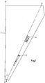
- the funnel plate 1 is cut out of a flat plate.
- two former plates are used to produce a former, which are symmetrical to the line A-A.
- outlet openings 2 are made in the funnel plate 1 by punching or drilling. If the outlet openings 2 are punched out, it is also possible to provide square, rectangular or slot-shaped openings. In addition, by chamfering the openings on the inside and outside, the air's noise can be reduced.
- one longitudinal edge is bent in a press along the bending lines B-B to produce a conically tapering edge contour 3.
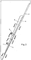
- the course of the edge contour 3 results from FIGS. 3 to 6.
- Cores are now inserted into the interior of the edge contours 3, the cross-sectional area of which corresponds to the desired cross-section of the compressed air supply chambers 4 and 5.
- a core is used for each closed compressed air supply chamber.
- a narrow cavity remains between the cores.
- the cores are made of a solvent-soluble material.
- the cores are expediently made from Styropor®.
- Each core also carries a compressed air supply nozzle 6 or 7.
- the cores are back-cast with a hardenable plastic, so that there is a wall 8 made of plastic at a distance from the tip of the edge contour 3, which carries the compressed air supply connections 6, 7. Plastic also penetrates into the cavity between two cores, which, as shown in FIG. 5, forms a partition 9.
- An epoxy resin, a silicone resin or a polyurethane resin is expediently used as the hardenable plastic.
- a solvent for the cores is introduced through the compressed air supply connections 6, 7.
- Trichlorethylene or tetrachlorethylene is expediently used as solvent, since these agents dissolve the core material, but do not attack the hardened plastic of the wall 8.
- tetrachlorethylene is expediently used as solvent, since these agents dissolve the core material, but do not attack the hardened plastic of the wall 8.
Landscapes
- Engineering & Computer Science (AREA)
- Mechanical Engineering (AREA)
- Casting Or Compression Moulding Of Plastics Or The Like (AREA)
- Folding Of Thin Sheet-Like Materials, Special Discharging Devices, And Others (AREA)
- Moulds For Moulding Plastics Or The Like (AREA)
- Printing Plates And Materials Therefor (AREA)
Description
- Die Erfindung bezieht sich auf ein Verfahren zum Herstellen eines Trichterbleches für einen Falztrichter einer Rotationsdruckmaschine, dessen Längskanten Druckluftzuführungskammern mit Austrittsöffnungen aufweisen und auf ein danach hergestelltes Trichterblech.
- Derartige Falztrichter sind aus der DE-AS 2240397 bekannt. Werden die Längskanten durch Rohre konstanten Durchmessers gebildet, so ist zwar der fertigungstechnische Aufwand gering. Aus Gründen einer einwandfreien Führung der Papierbahnen über dem Falztrichter ist es jedoch erwünscht, dass der Krümmungsradius der Längskanten zur Trichterspitze hin laufend abnimmt. Die Herstellung hierfür verwendbarer konischer Rohre ist aber fertigungstechnisch sehr aufwendig.
- Der Erfindung liegt die Aufgabe zugrunde, ein Herstellungsverfahren für ein Trichterblech der eingangs genannten Gattung sowie ein derartiges Trichterblech zu schaffen, das bei geringem Fertigungsaufwand-mit konisch zulaufenden Längskanten ausgeführt werden kann.
- Erfindungsgemäss wird dies durch die Massnahmen der Ansprüche 1 und 5 erreicht.
- Weitere Merkmale und Vorteile der Erfindung ergeben sich aus den Unteransprüchen in Verbindung mit der nachfolgenden Beschreibung eines Ausführungsbeispieles anhand der Zeichnung. Auf dieser zeigt
- Fig. 1 ein Trichterblech vor der Verformung der Randkontur in einer Rückansicht,
- Fig. das fertige Trichterblech in einer der Fig. 1 e: sprechenden Darstellung sowie die
- Fig.3 bis 6 Schnitte entlang der Linien 111-111 bis VI-VI in Fig. 2.
- Wie Fig. 1 erkennen lässt, wird das Trichterblech 1 aus einem ebenen Blech ausgeschnitten. Dabei finden zur Herstellung eines Falztrichters zwei Trichterbleche Verwendung, die zur Linie A-A symmetrisch ausgebildet sind. Nach dem Ausschneiden werden Austrittsöffnungen 2 durch Stanzen oder Bohren in das Trichterblech 1 eingebracht. Sofern die Austrittsöffnungen 2 ausgestanzt werden, besteht die Möglichkeit, auch quadratische, rechteckige oder schlitzförmige Öffnungen vorzusehen. Ausserdem kann durch Anfasen der Öffnungen innen und aussen das Austrittsgeräusch der Luft vermindert werden.
- In einem nächsten Bearbeitungsschritt wird in einer Presse die eine Längskante entlang der Biegelinien B-B zur Erzeugung einer konisch zulaufenden Randkontur 3 abgebogen. Der Verlauf der Randkontur 3 ergibt sich aus den Figuren 3 bis 6.
- In den Innenraum der Randkonturen 3 werden nunmehr Kerne eingelegt, deren Querschnittsfläche dem jeweils gewünschten Querschnitt der Druckluftzuführungskammern 4 und 5 entspricht. Dabei wird für jede abgeschlossene Druckluftzuführungskammer ein Kern verwendet. Zwischen den Kernen verbleibt ein schmaler Hohlraum. Die Kerne bestehen aus einem mittels eines Lösungsmittels auflösbaren Werkstoff. Zweckmässig sind die Kerne aus Styropor® hergestellt. Jeder Kern trägt weiterhin einen Druckluftzuführungsstutzen 6 bzw. 7.
- In einem weiteren Arbeitsgang werden die Kerne mit einem aushärtbaren Kunststoff hintergossen, so dass sich in Abstand von der Spitze der Randkontur 3 eine Wandung 8 aus Kunststoff ergibt, die die Druckluftzuführungsstutzen 6, 7 trägt. Dabei dringt in den Hohlraum zwischen zwei Kernen ebenfalls Kunststoff ein, der, wie Fig. 5 zeigt, eine Trennwand 9 bildet. Als aushärtbarer Kunststoff wird zweckmässig ein Epoxydharz, ein Silixonharz oder ein Polyurethanharz verwendet.
- Nach dem Aushärten des Kunststoffs wird durch die Druckluftzuführungsstutzen 6, 7 ein Lösungsmittel für die Kerne eingeführt. Als Lösungsmittel wird zweckmässig Trichloräthylen oder Tetrachloräthylen verwendet, da diese Mittel zwar den Kernwerkstoff auflösen, jedoch den ausgehärteten Kunststoff der Wandung 8 nicht angreifen. Nach Auflösung der Kerne wird deren Werkstoff in flüssiger Form durch die Druckluftzuführungsstutzen 6, 7 abgeführt.
- Durch das Hintergiessen verlorener, in die Randkonturen 3 eingelegter Kerne mit Kunststoff besteht die Möglichkeit, entsprechend den jeweiligen Anforderungen in einfacher Weise mehrere Druckluftzuführungskammern entlang des Randes des Trichterbleches 1 vorzusehen. Dabei kann ohne zusätzlichen Fertigungsaufwand die Querschnittsfläche dieser Kammern kontinuierlich geändert werden. Durch die vorgesehene Zahl und Querschnittsflächengestaltung der Druckluftzuführungskammern in Verbindung mit der Lage, Grösse und Form der Austrittsöffnungen kann eine optimale Luftdosierung erreicht werden. Ausserdem besteht die Möglichkeit, die einzelnen Kammern mit Luft unterschiedlichen Drucks zu beaufschlagen. Die Trennwände zwischen den Druckluftzuführungskammern 4, 5 fallen ebenfalls ohne zusätztiche Fertigungsschritte an. Durch das Hintergiessen mit aushärtbarem Kunststoff entfällt auch die Gefahr einer Verformung des Trichterbleches, die beispielsweise auftreten kann, wenn ein konisch zulaufendes Rohr an ein Trichterblech angeschweisst wird.
- Wie die Beschreibung zeigt, ist die Erfindung nicht auf das dargestellte Ausführungsbeispiel beschränkt.
Claims (6)
Applications Claiming Priority (2)
| Application Number | Priority Date | Filing Date | Title |
|---|---|---|---|
| DE19792921757 DE2921757A1 (de) | 1979-05-29 | 1979-05-29 | Verfahren zum herstellen eines trichterbleches fuer einen falztrichter einer rotationsdruckmaschine und danach hergestelltes trichterblech |
| DE2921757 | 1979-05-29 |
Publications (2)
| Publication Number | Publication Date |
|---|---|
| EP0019708A1 EP0019708A1 (de) | 1980-12-10 |
| EP0019708B1 true EP0019708B1 (de) | 1982-12-01 |
Family
ID=6071939
Family Applications (1)
| Application Number | Title | Priority Date | Filing Date |
|---|---|---|---|
| EP80101927A Expired EP0019708B1 (de) | 1979-05-29 | 1980-04-10 | Verfahren zum Herstellen eines Trichterbleches für einen Falztrichter einer Rotationsdruckmaschine und danach hergestelltes Trichterblech |
Country Status (4)
| Country | Link |
|---|---|
| US (1) | US4321051A (de) |
| EP (1) | EP0019708B1 (de) |
| JP (1) | JPS55161749A (de) |
| DE (2) | DE2921757A1 (de) |
Families Citing this family (15)
| Publication number | Priority date | Publication date | Assignee | Title |
|---|---|---|---|---|
| US4464160A (en) * | 1981-09-14 | 1984-08-07 | Tex-Fab, Inc. | Method and apparatus for forming a hem in fabric flat goods |
| JPS5957445U (ja) * | 1982-10-06 | 1984-04-14 | 小森印刷機械株式会社 | 巻紙輪転印刷機の折機 |
| JPS59159667U (ja) * | 1983-04-11 | 1984-10-26 | 株式会社小森コーポレーション | 巻紙輪転印刷機のフオ−マ構造 |
| DD215278A1 (de) * | 1983-05-26 | 1984-11-07 | Polygraph Leipzig | Laengsfalztrichter fuer rollenrotations-druckmaschinen |
| EP0240872A1 (de) * | 1986-04-10 | 1987-10-14 | Vinod Kapoor | Apparat zum Falten von Bahnen |
| FR2633869A1 (fr) * | 1988-07-05 | 1990-01-12 | Holweg Int | Mandrin de formage d'un boyau a soufflets |
| DE4228447C2 (de) * | 1992-08-26 | 1994-07-14 | Roland Man Druckmasch | Verfahren zum Herstellen eines Trichterbleches für einen Falztrichter einer Rotationsdruckmaschine |
| DE4435528C2 (de) * | 1994-10-05 | 1997-09-04 | Roland Man Druckmasch | Falztrichter für eine Druckmaschine |
| US5947411A (en) * | 1998-03-26 | 1999-09-07 | Heidelberger Druckmaschinen Ag | Method and apparatus for air flotation |
| US6673003B2 (en) * | 2001-05-09 | 2004-01-06 | The Procter & Gamble Company | Vacuum cleaning folding rail |
| US7144356B2 (en) * | 2002-05-10 | 2006-12-05 | The Procter & Gamble Company | Adjustable, self-correcting web substrate folding system |
| ATE390280T1 (de) | 2002-10-19 | 2008-04-15 | Koenig & Bauer Ag | Leitelemente einer druckeinheit |
| ATE388918T1 (de) * | 2003-02-19 | 2008-03-15 | Koenig & Bauer Ag | Druckmaschine mit einem wendewerk |
| DE102012201238B3 (de) * | 2012-01-30 | 2012-12-27 | Koenig & Bauer Aktiengesellschaft | Vorrichtung einer Rollenrotationsdruckmaschine zur Verarbeitung einer oder mehrerer bedruckter Bahnen sowie Verfahren zur Bildung eines längsgefalzten Stranges |
| DE102021103766A1 (de) * | 2021-02-17 | 2022-08-18 | Manroland Goss Web Systems Gmbh | Trichternase und Falztrichter |
Family Cites Families (4)
| Publication number | Priority date | Publication date | Assignee | Title |
|---|---|---|---|---|
| US2997296A (en) * | 1961-01-31 | 1961-08-22 | Bash Edward J La | Tape folders |
| US3111310A (en) * | 1961-12-21 | 1963-11-19 | Orville V Dutro | Folder |
| DE2240397B1 (de) * | 1972-08-17 | 1974-02-07 | Maschinenfabrik Augsburg-Nürnberg AG, 8900 Augsburg | Falztrichter fuer rotationsdruckmaschinen |
| UST952006I4 (de) * | 1975-07-28 | 1976-11-02 |
-
1979
- 1979-05-29 DE DE19792921757 patent/DE2921757A1/de not_active Withdrawn
-
1980
- 1980-04-10 DE DE8080101927T patent/DE3061194D1/de not_active Expired
- 1980-04-10 EP EP80101927A patent/EP0019708B1/de not_active Expired
- 1980-04-30 US US06/145,355 patent/US4321051A/en not_active Expired - Lifetime
- 1980-05-27 JP JP6969780A patent/JPS55161749A/ja active Granted
Also Published As
| Publication number | Publication date |
|---|---|
| DE2921757A1 (de) | 1980-12-04 |
| JPH0117981B2 (de) | 1989-04-03 |
| DE3061194D1 (en) | 1983-01-05 |
| US4321051A (en) | 1982-03-23 |
| EP0019708A1 (de) | 1980-12-10 |
| JPS55161749A (en) | 1980-12-16 |
Similar Documents
| Publication | Publication Date | Title |
|---|---|---|
| EP0019708A1 (de) | Verfahren zum Herstellen eines Trichterbleches für einen Falztrichter einer Rotationsdruckmaschine und danach hergestelltes Trichterblech | |
| DE2535733A1 (de) | Verfahren zur herstellung einer bewaesserungsleitung | |
| DE102014108463A1 (de) | Wärmeübertragerrohr und Verfahren zur Herstellung eines Wärmeübertragerrohrs | |
| DE2430656C2 (de) | Preßstempel zum Herstellen eines Külbels | |
| DE10063211C2 (de) | Verfahren zur Herstellung einer Mehrkammertube | |
| DE2557380C2 (de) | Verformungswerkzeug für die Herstellung eines gewellten Innenrohres eines doppelwandigen Tropfbewässerungsrohres mit glattwandigem Außenrohr | |
| DE2642523A1 (de) | Verfahren und vorrichtung zur herstellung eines flugzeugbauteils in profilverstaerkter schalenbauweise | |
| DE202019101313U1 (de) | Strahlregler | |
| DE102007021075B4 (de) | Verbindungsanordnung zum Verbinden zweier gekrümmter Spanten eines Luft- oder Raumfahrzeugs | |
| AT516506B1 (de) | Verfahren und Vorrichtung zum Schmieden eines stabförmigen Werkstücks | |
| DE102004018251A1 (de) | Entformstation | |
| DE19706838A1 (de) | Verfahren und Vorrichtung zur Herstellung von Kunststoff-Formteilen durch Blasformen | |
| DE19911125C1 (de) | Verfahren und Vorrichtung zum Trennen oder Lochen eines Werkstücks unter Einfluß eines unter Hochdruck stehenden Druckmediums | |
| DE19544190B4 (de) | Hydrodynamischer Retarder oder hydrodynamische Kupplung | |
| DE2447653C3 (de) | Gedruckte Schaltung | |
| DE4340081C2 (de) | Vorrichtung zum Herstellen von Wabenstrukturkörpern | |
| EP3586990B1 (de) | Verfahren zur erhöhung der mechanischen stabilität eines randbereichs | |
| DE4018129C2 (de) | Gußmodell und damit hergestellte Gußstücke | |
| DE2220301C3 (de) | Verfahren und Vorrichtung zum Einfuhren des Blasfluids in einen hohlen Vorformling aus thermoplastischem Kunststoff | |
| DE911581C (de) | Hohlblatt fuer Luftschrauben | |
| DE2030227C3 (de) | Verfahren zur Herstellung eines mit einem Anschlußstutzen versehenen Plattenradiators | |
| DE2254292A1 (de) | Schwingkoerper fuer elektroakustischen wandler | |
| DE414127C (de) | Verfahren zur Formung von tiefen Hohlkoerpern | |
| DE1660245A1 (de) | Verfahren und Vorrichtung zum Herstellen von Zwei-Komponenten-fasern | |
| DE4405630A1 (de) | Deckenauslaß |
Legal Events
| Date | Code | Title | Description |
|---|---|---|---|
| PUAI | Public reference made under article 153(3) epc to a published international application that has entered the european phase |
Free format text: ORIGINAL CODE: 0009012 |
|
| AK | Designated contracting states |
Designated state(s): CH DE FR GB SE |
|
| 17P | Request for examination filed |
Effective date: 19801220 |
|
| GRAA | (expected) grant |
Free format text: ORIGINAL CODE: 0009210 |
|
| AK | Designated contracting states |
Designated state(s): CH DE FR GB SE |
|
| REF | Corresponds to: |
Ref document number: 3061194 Country of ref document: DE Date of ref document: 19830105 |
|
| ET | Fr: translation filed | ||
| REG | Reference to a national code |
Ref country code: CH Ref legal event code: PFA Free format text: M.A.N.-ROLAND DRUCKMASCHINEN AKTIENGESELLSCHAFT |
|
| PGFP | Annual fee paid to national office [announced via postgrant information from national office to epo] |
Ref country code: CH Payment date: 19930315 Year of fee payment: 14 |
|
| PGFP | Annual fee paid to national office [announced via postgrant information from national office to epo] |
Ref country code: SE Payment date: 19930322 Year of fee payment: 14 |
|
| PG25 | Lapsed in a contracting state [announced via postgrant information from national office to epo] |
Ref country code: SE Effective date: 19940411 |
|
| PG25 | Lapsed in a contracting state [announced via postgrant information from national office to epo] |
Ref country code: LI Effective date: 19940430 Ref country code: CH Effective date: 19940430 |
|
| REG | Reference to a national code |
Ref country code: CH Ref legal event code: PL |
|
| EUG | Se: european patent has lapsed |
Ref document number: 80101927.4 Effective date: 19941110 |
|
| PGFP | Annual fee paid to national office [announced via postgrant information from national office to epo] |
Ref country code: GB Payment date: 19980312 Year of fee payment: 19 |
|
| PGFP | Annual fee paid to national office [announced via postgrant information from national office to epo] |
Ref country code: FR Payment date: 19980313 Year of fee payment: 19 |
|
| PGFP | Annual fee paid to national office [announced via postgrant information from national office to epo] |
Ref country code: DE Payment date: 19980318 Year of fee payment: 19 |
|
| PG25 | Lapsed in a contracting state [announced via postgrant information from national office to epo] |
Ref country code: GB Free format text: LAPSE BECAUSE OF NON-PAYMENT OF DUE FEES Effective date: 19990410 |
|
| GBPC | Gb: european patent ceased through non-payment of renewal fee |
Effective date: 19990410 |
|
| PG25 | Lapsed in a contracting state [announced via postgrant information from national office to epo] |
Ref country code: FR Free format text: LAPSE BECAUSE OF NON-PAYMENT OF DUE FEES Effective date: 19991231 |
|
| REG | Reference to a national code |
Ref country code: FR Ref legal event code: ST |
|
| PG25 | Lapsed in a contracting state [announced via postgrant information from national office to epo] |
Ref country code: DE Free format text: LAPSE BECAUSE OF NON-PAYMENT OF DUE FEES Effective date: 20000201 |
|
| PLBE | No opposition filed within time limit |
Free format text: ORIGINAL CODE: 0009261 |
|
| STAA | Information on the status of an ep patent application or granted ep patent |
Free format text: STATUS: NO OPPOSITION FILED WITHIN TIME LIMIT |