EP0019656B1 - Filtre à rinçage à contre-courant - Google Patents
Filtre à rinçage à contre-courant Download PDFInfo
- Publication number
- EP0019656B1 EP0019656B1 EP79103014A EP79103014A EP0019656B1 EP 0019656 B1 EP0019656 B1 EP 0019656B1 EP 79103014 A EP79103014 A EP 79103014A EP 79103014 A EP79103014 A EP 79103014A EP 0019656 B1 EP0019656 B1 EP 0019656B1
- Authority
- EP
- European Patent Office
- Prior art keywords
- water
- air
- filter
- pipes
- drainage pipes
- Prior art date
- Legal status (The legal status is an assumption and is not a legal conclusion. Google has not performed a legal analysis and makes no representation as to the accuracy of the status listed.)
- Expired
Links
Images


Classifications
-
- B—PERFORMING OPERATIONS; TRANSPORTING
- B01—PHYSICAL OR CHEMICAL PROCESSES OR APPARATUS IN GENERAL
- B01D—SEPARATION
- B01D24/00—Filters comprising loose filtering material, i.e. filtering material without any binder between the individual particles or fibres thereof
- B01D24/02—Filters comprising loose filtering material, i.e. filtering material without any binder between the individual particles or fibres thereof with the filter bed stationary during the filtration
- B01D24/20—Filters comprising loose filtering material, i.e. filtering material without any binder between the individual particles or fibres thereof with the filter bed stationary during the filtration the filtering material being provided in an open container
- B01D24/24—Downward filtration, the container having distribution or collection headers or pervious conduits
-
- B—PERFORMING OPERATIONS; TRANSPORTING
- B01—PHYSICAL OR CHEMICAL PROCESSES OR APPARATUS IN GENERAL
- B01D—SEPARATION
- B01D24/00—Filters comprising loose filtering material, i.e. filtering material without any binder between the individual particles or fibres thereof
- B01D24/46—Regenerating the filtering material in the filter
- B01D24/4626—Construction of spray heads specially adapted for regeneration of the filter material or for filtrate discharging
-
- B—PERFORMING OPERATIONS; TRANSPORTING
- B01—PHYSICAL OR CHEMICAL PROCESSES OR APPARATUS IN GENERAL
- B01D—SEPARATION
- B01D24/00—Filters comprising loose filtering material, i.e. filtering material without any binder between the individual particles or fibres thereof
- B01D24/46—Regenerating the filtering material in the filter
- B01D24/4631—Counter-current flushing, e.g. by air
Definitions
- the invention relates to a backwashable filter system for purifying water, which comprises at least one filter field with a filter base carrying a layer of granular filter mass, in or on which drainage pipes are laid for collecting the filtrate, which are in a collecting channel lying below the filter base level lead for the filtrate, the system being provided with a backflushing device for combined air / water flushing of the filter field, the feed and distribution of the backflushing media also taking place through the drainage pipes, which are provided with connecting pipes protruding into the collecting duct and having at least one air inlet opening, and finally the feed lines for the backwash media are connected to the collecting duct.
- Filter systems of the present type in which drainage pipes are laid in or on the bottom of the filter field for the removal of the filtrate from the granular filter material, are known from FR-A-597 406; the openings in the drainage pipes for the filtrate and the rinsing media are directed upwards and horizontally to the side.
- the object of the invention is to provide a simple system for a combined air / water backflushing for such drainage tube filters, in which the amount of air required is considerably reduced, so that the most uniform possible distribution of air over the entire filter field before it emerges the drainage pipe into the granular filter mass is guaranteed.
- This object is achieved in that filter nozzles with downwardly directed nozzle heads are inserted into the drainage pipes, in which flow openings of different overall cross-section for purging air and rinsing water are present, at least the large cross-section openings intended for the water being closable.
- the equal distribution of the air both in the longitudinal direction - as such, the direction of the collecting channel for the filtrate - and in the transverse direction - which means the longitudinal direction of the drainage pipes - is, as in the known system, by the formation of a double air cushion before it emerges in reached the filter field; All drainage pipes are supplied with both flushing media, there is no local separation of the air and water flushing.
- a granular filter mass 8 is stored, above which there is an storage space 14 for the raw water to be filtered.
- parallel drainage pipes 2 cover the filter base 13, which are used during the filtering operation to collect and discharge the filtrate and during backwashing to supply and distribute the flushing media.
- the drainage pipes 2 are provided with filter nozzles 15, whose heads 3 are oriented downwards, while the nozzle shafts 26 point upwards.
- Each drainage pipe 2 has a connection or immersion pipe 5 which runs vertically through the filter base 13 and which opens into a pure water collecting duct 4.
- the dip tubes 5 have air openings 9 located at the same level from their free end.
- the filtrate is discharged via a line 6 during filter operation.
- the line 6 is also the supply line for backwashing water, while the air required for backwashing is fed to the collecting duct 4 via a line 7.
- filter nozzles 15 are used according to the invention, in which a relatively low and for the flushing air the rinsing water has a relatively large total cross section at through-flow openings 33 and 31 (FIG. 3), the through-flow openings 31 depending on the liquid level 20 in the drainage pipes 2 be closed automatically for the water.
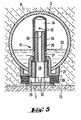
- FIG. 3 shows an embodiment of a filter nozzle of the type described above.
- the drainage pipe 2, in which the filter nozzles 15 are inserted, is supported in FIGS. 1 and 2 on the bottom 13 of the filter field 1 with the nozzle heads 3; the nozzle shaft 26 (Fig. 3) in the interior of the tube 2 is directed upwards.
- an intermediate or support ring 27 is first inserted through bores in the drainage pipe 2 and has a central threaded bore. At its inner upper end, this merges into a flow opening of smaller cross section. A flange of the nozzle shaft 26 protruding further into the tube and inserted through the throughflow opening abuts against the step that is created in this way. The shaft 26 is held by the nozzle head 3 screwed into the threaded bore of the intermediate ring 27, through which filter disks 30 simultaneously on the outside of the intermediate ring 27 are pressed.
- the internally hollow nozzle shaft 26 has adjacent its lower end first transit strömö réelleen '31, which in conjunction with a vertical cavity 28 and provided with ribs 32 horizontal cross connections 29 in the nozzle head 3, a first flow path between the filter box 1 and the inside of the drainage pipe 2 form through which the filtrate flows into the drainage pipe 2 during the filter operation and backwashing liquid into the filter field 1 during the rinsing.
- the throughflow openings 31 intended for the liquid flow have a relatively large total flow cross section.
- the nozzle shaft 26 has second throughflow openings 33 with a total flow cross section that is relatively small compared to the cross section of the first throughflow openings 31.
- a means for closing the first flow openings 31 in the cavity 34 of the nozzle shaft 26 is a float piston 35 which is displaceable with the level 20 of the water in the drain pipe 2 and through which the flow path through the flow openings 31 is closed in the drain pipe 2 when the water level 20 is lowered and at the same time off a flow path for air to the cavity 28 of the nozzle head 3 is opened to the air space above the lowered water level 20 through the flow openings 33 and a central channel 36 in the float piston 35; because air for an air purge flows on the second flow path, that is to say through the openings 33 and the channel 36, only into the cavity 28 and further through the cavity 29 and the filter disks 30 into the filter field 1 when the throughflow openings 31 are closed.
- the through-flow openings 31 are closed and released automatically by the falling or rising water level 20 in the drainage pipe 2; because when the liquid level is low, the buoyancy is no longer able to carry the float piston 35; it therefore sinks in the cavity 34 so far down that it rests on the nozzle head 3, which protrudes somewhat inwards relative to the nozzle shaft 26.
- the float piston 35 begins to float; from a certain level, it therefore releases the flow openings 31 again, while the air flow through the openings 33 is interrupted at the same time.
- the air cushion 10 When the air cushion 10 reaches the air inlet holes 9, the air simultaneously flows through the connecting pipes 4 into the drainage pipes 2. In order to get to the nozzle heads 3, the water in the drainage pipes 2 must first be displaced; a second air cushion 11 is formed in the longitudinal direction of the drainage pipes, i.e. in the transverse direction of the filter field.
- a collapse of the air cushion in the drainage pipes 2 - which could occur due to an outflow of all the supplied air through the relatively large flow openings 31 designed and designed for the water into the nozzles 15 closest to the immersion or connecting pipe 4 - thereby preventing the Flow-through openings 31 for the water are closed by the float piston 35 when the water level in the drainage pipes 2 is caused by the increasing air pressure, so that only the narrow flow-through openings 33 are available for the air inlet into the filter nozzles 15.
Claims (1)
- Installation de filtration lavable à contre-courant pour purifier de l'eau, qui comprend au moins une étendue de filtration ayant un fond de filtration portant une couche d'une masse granulaire de filtration et dans lequel ou sur lequel sont placés pour recueillir le filtrat des tubes de drainage qui mènent dans un canal collecteur se trouvant en dessous du niveau du fond de filtration, l'installation étant pourvue d'un dispositif de lavage à contre-courant pour le lavage combiné aireau de l'étendue de filtration, et les milieux de lavage à contre-courant étant amenés et distribués par les tubes de drainage qui sont équipés de tubes de raccordement présentant au moins un orifice d'entrée d'air et pénétrant dans le canal collecteur, et les conduites d'arrivée des milieux de lavage à contre-courant étant finalement raccordées au canal collecteur, installation caractérisée en ce qu'on introduit dans les tubes de drainage (2) des buses de filtration (15) ayant des têtes (3) dirigées vers le bas dans lesquelles sont disponibles des orifices de passage (33 ou 31) de sections transversales totales différentes pour l'air de lavage et l'eau de lavage, au moins les orifices (31) de passage destinés à l'eau et de section transversale importante pouvant alors être bloqués.
Priority Applications (1)
| Application Number | Priority Date | Filing Date | Title |
|---|---|---|---|
| AT79103014T ATE1737T1 (de) | 1979-05-31 | 1979-08-17 | Rueckspuelbare filteranlage. |
Applications Claiming Priority (2)
| Application Number | Priority Date | Filing Date | Title |
|---|---|---|---|
| CH508679A CH639864A5 (de) | 1979-05-31 | 1979-05-31 | Rueckspuelbare filteranlage zum reinigen von wasser. |
| CH5086/79 | 1979-05-31 |
Publications (2)
| Publication Number | Publication Date |
|---|---|
| EP0019656A1 EP0019656A1 (fr) | 1980-12-10 |
| EP0019656B1 true EP0019656B1 (fr) | 1982-11-03 |
Family
ID=4287704
Family Applications (1)
| Application Number | Title | Priority Date | Filing Date |
|---|---|---|---|
| EP79103014A Expired EP0019656B1 (fr) | 1979-05-31 | 1979-08-17 | Filtre à rinçage à contre-courant |
Country Status (4)
| Country | Link |
|---|---|
| EP (1) | EP0019656B1 (fr) |
| AT (1) | ATE1737T1 (fr) |
| CH (1) | CH639864A5 (fr) |
| DE (1) | DE2963976D1 (fr) |
Families Citing this family (4)
| Publication number | Priority date | Publication date | Assignee | Title |
|---|---|---|---|---|
| CH661954A5 (de) * | 1982-09-02 | 1987-08-31 | Sulzer Ag | Vorrichtung zur fixierung von drainagerohren. |
| FR2557558B1 (fr) * | 1984-01-02 | 1986-05-23 | Degremont Sa | Filtre immerge a remplissage de materiau granulaire |
| DE3938607A1 (de) * | 1989-11-21 | 1991-05-23 | Didier Werke Ag | Verfahren und anlage zur filtration von suspensionen, emulsionen und/oder kuehlschmierstoffen |
| CN112824329B (zh) * | 2019-11-20 | 2022-05-17 | 南京大学 | 一种模块化滤池布水布气装置及其系统和应用方法 |
Family Cites Families (4)
| Publication number | Priority date | Publication date | Assignee | Title |
|---|---|---|---|---|
| FR597406A (fr) * | 1925-11-20 | |||
| GB191421120A (en) * | 1914-10-17 | 1915-10-14 | Frank Pullen Candy | Improvements in or in connection with Filters. |
| DE647368C (de) * | 1935-01-25 | 1937-07-02 | Oskar Brandes | Vorrichtung zum Rueckspuelen von Fluessigkeitsfiltern |
| FR1013722A (fr) * | 1950-01-13 | 1952-08-04 | Trailigaz | Perfectionnements à la réalisation des filtres à sable |
-
1979
- 1979-05-31 CH CH508679A patent/CH639864A5/de not_active IP Right Cessation
- 1979-08-17 DE DE7979103014T patent/DE2963976D1/de not_active Expired
- 1979-08-17 AT AT79103014T patent/ATE1737T1/de not_active IP Right Cessation
- 1979-08-17 EP EP79103014A patent/EP0019656B1/fr not_active Expired
Also Published As
| Publication number | Publication date |
|---|---|
| DE2963976D1 (en) | 1982-12-09 |
| ATE1737T1 (de) | 1982-11-15 |
| EP0019656A1 (fr) | 1980-12-10 |
| CH639864A5 (de) | 1983-12-15 |
Similar Documents
| Publication | Publication Date | Title |
|---|---|---|
| DE1611158C3 (de) | Filtereinrichtung | |
| DE1761106C3 (de) | Filter zur Reinigung von mit Feststoffen vermischten Flüssigkeiten | |
| DE1792219A1 (de) | Vorrichtung zum Abscheiden einer suspendierten Fluessigkeit aus einer Traegerfluessigkeit | |
| DE1947538B2 (de) | Vorrichtung zur wasseraufbereitung in einem druckwind-schaltkessel | |
| DE1461395C3 (de) | Steuereinrichtung für die Flüssigkeitsströme in einer Filteranlage | |
| DE60006528T2 (de) | Filterunterdrainagesystem | |
| EP0019656B1 (fr) | Filtre à rinçage à contre-courant | |
| DE2219081A1 (de) | Siebeinsatz für die Bodenplatte eines Filterbetts | |
| DE2104861B2 (de) | Verfahren und Vorrichtung zur kontinuierlichen Filtration von Flüssigkeiten | |
| DE2353541A1 (de) | Anordnung in filtergeraeten | |
| EP0789611B1 (fr) | Dispositif a filtres en forme de bougie utilise pour la filtration de biere | |
| DE2436965C2 (de) | Filter zum Filtern von Flüssigkeiten | |
| EP0305606B1 (fr) | Dispositif de filtration à nettoyage par contre-courant | |
| EP0144360B1 (fr) | Filtres a cartouche et installation de filtrage | |
| DE3108948C2 (de) | Flüssigkeitsfilter, insbesondere für Hydraulikmedien | |
| DE10152047B4 (de) | Vorrichtung und Verfahren zur Reinigung von Abwasser | |
| DE2537608C3 (de) | Automatisch arbeitende RückspiUvorrichtung für ein Schwerkraftfilter | |
| EP0232448B1 (fr) | Tube de drainage pour filtre à tube de drainage se lavant à contre courant | |
| CH642865A5 (de) | Apparat zum reinigen einer fluessigkeit. | |
| AT282648B (de) | Einrichtung zur Feinaufbereitung von Rohwasser | |
| DE2333725A1 (de) | Verfahren und vorrichtung zur unterdrueckung von expansionserscheinungen in einem bett aus koernigem material | |
| AT412841B (de) | Filteranlage und verfahren zum betreiben einer filteranlage | |
| DE2600193C3 (fr) | ||
| CH626814A5 (fr) | ||
| DD231737A1 (de) | Liegender druckfilter |
Legal Events
| Date | Code | Title | Description |
|---|---|---|---|
| PUAI | Public reference made under article 153(3) epc to a published international application that has entered the european phase |
Free format text: ORIGINAL CODE: 0009012 |
|
| 17P | Request for examination filed | ||
| AK | Designated contracting states |
Designated state(s): AT DE FR GB IT NL |
|
| ITF | It: translation for a ep patent filed |
Owner name: ING. ZINI MARANESI & C. S.R.L. |
|
| GRAA | (expected) grant |
Free format text: ORIGINAL CODE: 0009210 |
|
| AK | Designated contracting states |
Designated state(s): AT DE FR GB IT NL |
|
| REF | Corresponds to: |
Ref document number: 1737 Country of ref document: AT Date of ref document: 19821115 Kind code of ref document: T |
|
| REF | Corresponds to: |
Ref document number: 2963976 Country of ref document: DE Date of ref document: 19821209 |
|
| PGFP | Annual fee paid to national office [announced via postgrant information from national office to epo] |
Ref country code: FR Payment date: 19840621 Year of fee payment: 6 |
|
| PGFP | Annual fee paid to national office [announced via postgrant information from national office to epo] |
Ref country code: DE Payment date: 19840824 Year of fee payment: 6 |
|
| PGFP | Annual fee paid to national office [announced via postgrant information from national office to epo] |
Ref country code: AT Payment date: 19860821 Year of fee payment: 8 |
|
| PGFP | Annual fee paid to national office [announced via postgrant information from national office to epo] |
Ref country code: NL Payment date: 19870831 Year of fee payment: 9 |
|
| PG25 | Lapsed in a contracting state [announced via postgrant information from national office to epo] |
Ref country code: GB Free format text: LAPSE BECAUSE OF NON-PAYMENT OF DUE FEES Effective date: 19880817 Ref country code: AT Effective date: 19880817 |
|
| PG25 | Lapsed in a contracting state [announced via postgrant information from national office to epo] |
Ref country code: NL Effective date: 19890301 |
|
| NLV4 | Nl: lapsed or anulled due to non-payment of the annual fee | ||
| PG25 | Lapsed in a contracting state [announced via postgrant information from national office to epo] |
Ref country code: FR Free format text: LAPSE BECAUSE OF NON-PAYMENT OF DUE FEES Effective date: 19890428 |
|
| PG25 | Lapsed in a contracting state [announced via postgrant information from national office to epo] |
Ref country code: DE Effective date: 19890503 |
|
| GBPC | Gb: european patent ceased through non-payment of renewal fee | ||
| REG | Reference to a national code |
Ref country code: FR Ref legal event code: ST |
|
| PLBE | No opposition filed within time limit |
Free format text: ORIGINAL CODE: 0009261 |
|
| STAA | Information on the status of an ep patent application or granted ep patent |
Free format text: STATUS: NO OPPOSITION FILED WITHIN TIME LIMIT |