EP0019656B1 - Backwash filtration device - Google Patents
Backwash filtration device Download PDFInfo
- Publication number
- EP0019656B1 EP0019656B1 EP79103014A EP79103014A EP0019656B1 EP 0019656 B1 EP0019656 B1 EP 0019656B1 EP 79103014 A EP79103014 A EP 79103014A EP 79103014 A EP79103014 A EP 79103014A EP 0019656 B1 EP0019656 B1 EP 0019656B1
- Authority
- EP
- European Patent Office
- Prior art keywords
- water
- air
- filter
- pipes
- drainage pipes
- Prior art date
- Legal status (The legal status is an assumption and is not a legal conclusion. Google has not performed a legal analysis and makes no representation as to the accuracy of the status listed.)
- Expired
Links
Images


Classifications
-
- B—PERFORMING OPERATIONS; TRANSPORTING
- B01—PHYSICAL OR CHEMICAL PROCESSES OR APPARATUS IN GENERAL
- B01D—SEPARATION
- B01D24/00—Filters comprising loose filtering material, i.e. filtering material without any binder between the individual particles or fibres thereof
- B01D24/02—Filters comprising loose filtering material, i.e. filtering material without any binder between the individual particles or fibres thereof with the filter bed stationary during the filtration
- B01D24/20—Filters comprising loose filtering material, i.e. filtering material without any binder between the individual particles or fibres thereof with the filter bed stationary during the filtration the filtering material being provided in an open container
- B01D24/24—Downward filtration, the container having distribution or collection headers or pervious conduits
-
- B—PERFORMING OPERATIONS; TRANSPORTING
- B01—PHYSICAL OR CHEMICAL PROCESSES OR APPARATUS IN GENERAL
- B01D—SEPARATION
- B01D24/00—Filters comprising loose filtering material, i.e. filtering material without any binder between the individual particles or fibres thereof
- B01D24/46—Regenerating the filtering material in the filter
- B01D24/4626—Construction of spray heads specially adapted for regeneration of the filter material or for filtrate discharging
-
- B—PERFORMING OPERATIONS; TRANSPORTING
- B01—PHYSICAL OR CHEMICAL PROCESSES OR APPARATUS IN GENERAL
- B01D—SEPARATION
- B01D24/00—Filters comprising loose filtering material, i.e. filtering material without any binder between the individual particles or fibres thereof
- B01D24/46—Regenerating the filtering material in the filter
- B01D24/4631—Counter-current flushing, e.g. by air
Abstract
Description
Die Erfindung betrifft eine rückspülbare Filteranlage zum Reinigen von Wasser, die wenigstens ein Filterfeld mit einem, eine Schicht körniger Filtermasse tragenden Filterboden umfasst, in oder auf dem zum Sammeln des Filtrats Drainage-Rohre verlegt sind, die in einen unter dem Filterboden-Niveau liegenden Sammelkanal für das Filtrat führen, wobei die Anlage mit einer Rückspülvorrichtung zur kombinierten Luft/Wasserspülung des Filterfeldes versehen ist, wobei weiterhin Zuführung und Verteilung der Rückspülmedien durch die Drainage-Rohre erfolgt, die mit in den Sammelkanal hineinragenden, mindestens eine Lufteinlassöffnung aufweisenden Anschlussrohren versehen sind, und wobei schliesslich die Zuführleitungen für die Rückspülmedien an den Sammelkanal angeschlossen sind.The invention relates to a backwashable filter system for purifying water, which comprises at least one filter field with a filter base carrying a layer of granular filter mass, in or on which drainage pipes are laid for collecting the filtrate, which are in a collecting channel lying below the filter base level lead for the filtrate, the system being provided with a backflushing device for combined air / water flushing of the filter field, the feed and distribution of the backflushing media also taking place through the drainage pipes, which are provided with connecting pipes protruding into the collecting duct and having at least one air inlet opening, and finally the feed lines for the backwash media are connected to the collecting duct.
Filteranlagen der vorliegenden Art, bei denen für die Ableitung des Filtrats aus dem körnigen Filtermaterial des Filterfeldes in oder auf dessen Boden Drainagerohre verlegt sind, sind aus der FR-A-597 406 bekannt; die Durchtrittsöffnungen in den Drainagerohren für das Filtrat bzw. die Spülmedien sind dabei nach oben und horizontal zur Seite gerichtet.Filter systems of the present type, in which drainage pipes are laid in or on the bottom of the filter field for the removal of the filtrate from the granular filter material, are known from FR-A-597 406; the openings in the drainage pipes for the filtrate and the rinsing media are directed upwards and horizontally to the side.
Werden diese Oeffnungen in an sich bekannter Weise mit Filterdüsen bestückt, deren Düsenköpfe gegen den Boden des Filterfeldes gerichtet sind, bereitet die Gleichverteilung der Spülluft erhebliche Schwierigkeiten, da die Durchströmquerschnitte der Düsen für eine Gleichverteilung der Luft zu gross sind, so dass durch die nahe dem Lufteintritt liegenden Düsen relativ zuviel Luft ausströmt; darüberhinaus ist infolge des grossen Gesamtströmungsquerschnitts die verbrauchte Spülluftmenge sehr gross.If these openings are equipped in a manner known per se with filter nozzles, the nozzle heads of which are directed towards the bottom of the filter field, the uniform distribution of the purge air presents considerable difficulties, since the flow cross-sections of the nozzles are too large for an equal distribution of the air, so that due to the near Air inlet nozzles relatively much air flows out; moreover, due to the large total flow cross-section, the amount of purge air consumed is very large.
Aufgabe der Erfindung ist es, für derartige Drainagerohr-Filter ein einfaches System für eine kombinierte Luft/Wasser-Rückspülung zu schaffen, bei dem die benötigte Luftmenge erheblich reduziert wird, so dass eine möglichst gleichmässige Verteilung der Luft über das ganze Filterfeld vor ihrem Austritt aus dem Drainagerohr in die körnige Filtermasse gewährleistet ist. Diese Aufgabe wird dadurch gelöst, dass in die Drainagerohre Filterdüsen mit nach unten gerichteten Düsenköpfen eingesetzt sind, in denen Durchströmöffnungen unterschiedlichen Gesamtquerschnitts für Spülluft und Spülwasser vorhanden sind, wobei mindestens die für das Wasser bestimmten Durchströmöffnungen grossen Querschnitts absperrbar sind.The object of the invention is to provide a simple system for a combined air / water backflushing for such drainage tube filters, in which the amount of air required is considerably reduced, so that the most uniform possible distribution of air over the entire filter field before it emerges the drainage pipe into the granular filter mass is guaranteed. This object is achieved in that filter nozzles with downwardly directed nozzle heads are inserted into the drainage pipes, in which flow openings of different overall cross-section for purging air and rinsing water are present, at least the large cross-section openings intended for the water being closable.
Die Gleichverteilung der Luft sowohl in Längsrichtung - als solche sei die Richtung des Sammelkanals für das Filtrat bezeichnet - als auch in Querrichtung - womit die Längsrichtung der Drainagerohre gemeint sei - wird wie bei der bekannten Anlage durch die Ausbildung eines Doppelluft-Polsters vor ihrem Austritt in das Filterfeld erreicht; alle Drainagerohre sind mit beiden Spülmedien beaufschlagt, eine örtliche Trennung der Luft- von der Wasserspülung findet nicht statt.The equal distribution of the air both in the longitudinal direction - as such, the direction of the collecting channel for the filtrate - and in the transverse direction - which means the longitudinal direction of the drainage pipes - is, as in the known system, by the formation of a double air cushion before it emerges in reached the filter field; All drainage pipes are supplied with both flushing media, there is no local separation of the air and water flushing.
Die erhebliche Reduzierung des Durchtrittsquerschnitts für die Luft in jeder einzelnen Düse gewährleistet durch den Aufbau eines Druckluft-Polsters die Gleichverteilung; durch den damit gleichzeitig stark reduzierten Gesamtquerschnitt ist die verbrauchte Luftmenge entscheidend reduziert.The considerable reduction in the passage cross-section for the air in each individual nozzle ensures uniform distribution through the construction of a compressed air cushion; the overall cross-section, which is greatly reduced, significantly reduces the amount of air consumed.
Im folgenden wird die Erfindung anhand von Ausführungsbeispielen im Zusammenhang mit der Zeichnung näher erläutert.
- Fig. 1 zeigt für ein erstes Ausführungsbeispiel einer erfindungsgemässen Filteranlage einen Längsschnitt I-I von Fig. 2 durch ein Filterfeld;
- Fig. 2 ist der Schnitt 11-11 von Fig. 1;
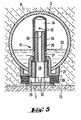
- Fig. 3 schliesslich zeigt eine Ausführungsform für eine spezielle Filterdüse.
- 1 shows a longitudinal section II of FIG. 2 through a filter field for a first exemplary embodiment of a filter system according to the invention;
- Fig. 2 is section 11-11 of Fig. 1;
- 3 finally shows an embodiment for a special filter nozzle.
Auf dem Boden 13 (Fig. 1) eines aus Beton gefertigten Filterfeldes 1 ist eine körnige Filtermasse 8 gelagert, über der sich ein Ueberstauraum 14 für das zu filtrierende Rohwasser befindet. In die Filtermasse 8 eingebettet bedecken parallel zueinander verlaufende Drainagerohre 2 den Filterboden 13, die während des Filterbetriebs zum Sammeln und Abführen des. Filtrats und während des Rückspülens zur Zuführung und Verteilung der Spülmedien dienen. Die Drainagerohre 2 sind mit Filterdüsen 15 versehen, die mit ihren Köpfen 3 nach unten orientiert sind, während die Düsenschäfte 26 nach oben zeigen.On the floor 13 (FIG. 1) of a
Jedes Drainagerohr 2 hat ein vertikal durch den Filterboden 13 verlaufendes Anschluss-oder Tauchrohr 5, das in einen Reinwassersammelkanal 4 mündet. Die Tauchrohre 5 haben in Abständen von ihrem freien Ende auf gleicher Niveauhöhe gelegene Luftöffnungen 9.Each
Aus dem Sammelkanal 4, der vertikal zur Achsrichtung der Drainagerohre 2 unter dem Boden 13 des Filterfeldes 1 über dessen ganze Länge verläuft, wird über eine Leitung 6 während des Filterbetriebs das Filtrat abgeführt. Die Leitung 6 ist gleichzeitig die Zuführleitung für Rückspülwasser, während die für das Rückspülen benötigte Luft über eine Leitung 7 dem Sammelkanal 4 zugeleitet wird.From the
Um bei Anlagen mit nach unten orientierten Düsenköpfen 3 bei abwechselnder und/oder kombinierter Luft/Wasser-Spülung eine gleichmässige Verteilung der Spülmedien über das ganze Filterfeld zu erhalten, werden gemäss der Erfindung Filterdüsen 15 eingesetzt, bei denen für die Spülluft ein relativ geringer und für das Spülwasser ein relativ grosser Gesamtquerschnitt an Durchströmöffnungen 33 bzw. 31 (Fig. 3) zur Verfügung steht, wobei in Abhängigkeit von dem Flüssigkeitsniveau 20 in den Drainagerohren 2 die Durchströmöffnungen 31 für das Wasser selbsttätig verschlossen werden. Eine Ausführungsform einer Filterdüse der vorstehend geschilderten Art zeigt Fig. 3.In order to obtain a uniform distribution of the flushing media over the entire filter field in systems with downwardly
Das Drainagerohr 2, in das die Filterdüsen 15 eingesetzt sind, ist in Fig. 1 und 2 auf dem Boden 13 des Filterfeldes 1 mit den Düsenköpfen 3 gelagert; der Düsenschaft 26 (Fig. 3) im Innern des Rohres 2 ist nach oben gerichtet.The
Für die Montage der Düsen 1 ist durch Bohrungen im Drainagerohr 2 zunächst ein Zwischen- oder Auflagering 27 gesteckt, der eine zentrale Gewindebohrung aufweist. Diese geht an ihrem inneren oberen Ende in eine Durchströmöffnung geringeren Querschnitts über. Gegen den so entstehenden Absatz stösst ein Flansch des weiter in das Rohr hineinragenden, durch die Durchströmöffnung hindurch gesteckten Düsenschaftes 26. Der Schaft 26 ist durch den in die Gewindebohrung des Zwischenrings 27 eingeschraubten Düsenkopf 3 gehalten, durch den gleichzeitig Filterscheiben 30 auf die Aussenseite des Zwischenrings 27 gepresst werden.For the assembly of the
Der innen hohle Düsenschaft 26 hat nahe seinem unteren Ende erste Durch- 'strömöffnungen 31, die in Verbindung mit einem vertikalen Hohlraum 28 und den mit Rippen 32 versehenen horizontalen Querverbindungen 29 im Düsenkopf 3 einen ersten Strömungsweg zwischen dem Filterfeld 1 und dem Innern des Drainagerohrs 2 bilden, durch den beim Filterbetrieb Filtrat in das Drainagerohr 2 und beim Spülen Rückspülflüssigkeit in das Filterfeld 1 fliessen. Die für die Flüssigkeitsströmung bestimmten Durchströmöffnungen 31 haben einen relativ grossen Gesamtströmungsquerschnitt.The internally
Auf einer Niveauhöhe oberhalb der ersten Durchströmöffnung 31 hat der Düsenschaft 26 zweite Durchströmöffnungen 33 mit gegenüber dem Querschnitt der ersten Durchströmöffnungen 31 relativ geringem Gesamtströmungsquerschnitt.At a level above the first throughflow opening 31, the
Als Mittel für das Verschliessen der ersten Durchströmöffnungen 31 ist im Hohlraum 34 des Düsenschaftes 26 ein mit der Niveauhöhe 20 des Wassers im Drainagerohr 2 verschiebbarer Schwimmerkolben 35 vorgesehen, durch den der Strömungsweg durch die Durchströmöffnungen 31 bei abgesenktem Wasserniveau 20 im Drainagerohr 2 verschlossen und gleichzeitig aus dem Luftraum über dem abgesenkten Wasserniveau 20 durch die Durchströmöffnungen 33 und einen zentralen Kanal 36 im Schwimmerkolben 35 ein Strömungsweg für Luft zum Hohlraum 28 des Düsenkopfes 3 geöffnet wird; denn Luft für eine Luftspülung strömt auf dem zweiten Strömungsweg, also durch die Oeffnungen 33 und den Kanal 36 nur in den Hohlraum 28 und weiter durch den Hohlraum 29 und die Filterscheiben 30 in das Filterfeld 1, wenn die Durchströmöffnungen 31 verschlossen sind.A means for closing the
Das Verschliessen und die Freigabe der Durchströmöffnungen 31 erfolgt selbsttätig durch das fallende bzw. steigende Wasserniveau 20 im Drainagerohr 2; denn bei niedrigem Flüssigkeitsstand vermag der Auftrieb den Schwimmerkolben 35 nicht mehr zu tragen, dieser sinkt daher im Hohlraum 34 so weit nach unten, dass er auf dem Düsenkopf 3 aufliegt, der gegenüber dem Düsenschaft 26 etwas nach innen vorspringt. Bei wieder steigendem Flüssigkeitsniveau beginnt der Schwimmerkolben 35 aufzuschwimmen; von einer gewissen Niveauhöhe ab gibt er daher die Durchströmöffnungen 31 wieder frei, während die Luftströmung durch die Oeffnungen 33 gleichzeitig unterbrochen wird.The through-
Eine im Rahmen der bekannten Luft/Wasser- Spülung durchzuführende Luftspülung nimmt mit einer Anlage gemäss dem beschriebenen ersten Ausführungsbeispiel folgenden Verlauf:
- Die Spülluft wird über die Leitung 7 in den
Kanal 5 gefördert. Da diese Luft erst durch dieLufteintrittslöcher 9 in dieAnschlussrohre 4 gelangen kann, muss vorerst das imKanal 5 befindliche Wasser bis auf die Höhe dieserLöcher 9 verdrängt werden und es kommt zur Bildung einesersten Luftpolsters 10, wodurch eine gleichmässige Verteilung der Luft über die ganze Länge des Filterfeldes, d.h. in Längsrichtung desSammelkanals 5, erzwungen wird.
- The purge air is conveyed into
duct 5 via line 7. Since this air can only get into the connectingpipes 4 through theair inlet holes 9, the water in thechannel 5 must first be displaced to the height of theseholes 9 and afirst air cushion 10 is formed, as a result of which a uniform distribution of the air over the Entire length of the filter field, ie in the longitudinal direction of thecollecting channel 5, is forced.
Erreicht das Luftpolster 10 die Lufteintrittslöcher 9, so strömt die Luft gleichzeitig durch die Anschlussrohre 4 in die Drainagerohre 2. Um zu den Düsenköpfen 3 zu gelangen, muss zunächst auch das in den Drainagerohren 2 befindliche Wasser verdrängt werden; es kommt zur Bildung eines zweiten Luftpolsters 11 in Längsrichtung der Drainagerohre, d.h. in Querrichtung des Filterfeldes.When the
Erreichen die Luftpolster 11 die Lufteintrittsöffnungen 33 der Düsen 5, so strömt die Luft gleichzeitig und gleichmässig verteilt aus allen Düsenköpfen 3 in die Filtermasse 8.When the air cushions 11 reach the
Ein Zusammenbrechen des Luftpolsters in den Drainagerohren 2 - was durch ein Abströmen der gesamten zugeführten Luft durch die relativ grossen für das Wasser bestimmten und ausgelegten Durchströmöffnungen 31 in den dem Tauchoder Anschlussrohr 4 am nächsten liegenden Düsen 15 eintreten könnte - wird dabei dadurch verhindert, dass die Durchströmöffnungen 31 für das Wasser bei durch den steigenden Luftdruck hervorgerufenem Absinken des Wasserspiegels in den Drainagerohren 2 von dem Schwimmerkolben 35 verschlossen werden, so dass für den Lufteintritt in die Filterdüsen 15 nur die engen Durchströmöffnungen 33 zur Verfügung stehen.A collapse of the air cushion in the drainage pipes 2 - which could occur due to an outflow of all the supplied air through the relatively
Claims (1)
- A backwashable filter installation for the purification of water, comprising at least one filter bed having a base bearing a layer of granular filter material, in or on which base drainage pipes are laid for collecting the filtrate, said pipes leading into a filtrate collecting duct beneath the level of the filter bed, the installation being provided with a backwashing system for combined air and water washing of the filter bed, the backwashing media further being supplied and distributed through the drainage pipes, which are provided with connecting pipes extending into the collecting duct and having at least one air inlet aperture, and the feed pipes for the backwashing medium are connected to the collecting duct, characterised in that strainers (15) with the strainer heads (3) extending downwards are fitted into the drainage pipes (2), said heads being formed with passage apertures (33 and 31) of different total cross-section for washing air and washing water, at least the large cross-section passage apertures (31) intended for the water being closable.
Priority Applications (1)
| Application Number | Priority Date | Filing Date | Title |
|---|---|---|---|
| AT79103014T ATE1737T1 (en) | 1979-05-31 | 1979-08-17 | BACKFLUSHABLE FILTER SYSTEM. |
Applications Claiming Priority (2)
| Application Number | Priority Date | Filing Date | Title |
|---|---|---|---|
| CH5086/79 | 1979-05-31 | ||
| CH508679A CH639864A5 (en) | 1979-05-31 | 1979-05-31 | BACKWASHABLE FILTER SYSTEM FOR CLEANING WATER. |
Publications (2)
| Publication Number | Publication Date |
|---|---|
| EP0019656A1 EP0019656A1 (en) | 1980-12-10 |
| EP0019656B1 true EP0019656B1 (en) | 1982-11-03 |
Family
ID=4287704
Family Applications (1)
| Application Number | Title | Priority Date | Filing Date |
|---|---|---|---|
| EP79103014A Expired EP0019656B1 (en) | 1979-05-31 | 1979-08-17 | Backwash filtration device |
Country Status (4)
| Country | Link |
|---|---|
| EP (1) | EP0019656B1 (en) |
| AT (1) | ATE1737T1 (en) |
| CH (1) | CH639864A5 (en) |
| DE (1) | DE2963976D1 (en) |
Families Citing this family (4)
| Publication number | Priority date | Publication date | Assignee | Title |
|---|---|---|---|---|
| CH661954A5 (en) * | 1982-09-02 | 1987-08-31 | Sulzer Ag | DEVICE FOR FIXING DRAINAGE TUBES. |
| FR2557558B1 (en) * | 1984-01-02 | 1986-05-23 | Degremont Sa | UNDERWATER FILTER FILLED WITH GRANULAR MATERIAL |
| DE3938607A1 (en) * | 1989-11-21 | 1991-05-23 | Didier Werke Ag | METHOD AND SYSTEM FOR FILTRATION OF SUSPENSIONS, EMULSIONS AND / OR COOLING LUBRICANTS |
| CN112824329B (en) * | 2019-11-20 | 2022-05-17 | 南京大学 | Water and gas distribution device for modular filter tank and system and application method thereof |
Family Cites Families (4)
| Publication number | Priority date | Publication date | Assignee | Title |
|---|---|---|---|---|
| FR597406A (en) * | 1925-11-20 | |||
| GB191421120A (en) * | 1914-10-17 | 1915-10-14 | Frank Pullen Candy | Improvements in or in connection with Filters. |
| DE647368C (en) * | 1935-01-25 | 1937-07-02 | Oskar Brandes | Device for backwashing liquid filters |
| FR1013722A (en) * | 1950-01-13 | 1952-08-04 | Trailigaz | Improvements in the production of sand filters |
-
1979
- 1979-05-31 CH CH508679A patent/CH639864A5/en not_active IP Right Cessation
- 1979-08-17 DE DE7979103014T patent/DE2963976D1/en not_active Expired
- 1979-08-17 EP EP79103014A patent/EP0019656B1/en not_active Expired
- 1979-08-17 AT AT79103014T patent/ATE1737T1/en not_active IP Right Cessation
Also Published As
| Publication number | Publication date |
|---|---|
| CH639864A5 (en) | 1983-12-15 |
| DE2963976D1 (en) | 1982-12-09 |
| EP0019656A1 (en) | 1980-12-10 |
| ATE1737T1 (en) | 1982-11-15 |
Similar Documents
| Publication | Publication Date | Title |
|---|---|---|
| DE2708340C3 (en) | Process for filtering a sludge or emulsion and filter device for carrying out the process | |
| DE1611158C3 (en) | Filter device | |
| DE1761106C3 (en) | Filters for cleaning liquids mixed with solids | |
| DE1792219A1 (en) | Device for separating a suspended liquid from a carrier liquid | |
| DE1947538B2 (en) | DEVICE FOR WATER TREATMENT IN A PRESSURE WIND SWITCHING BOILER | |
| DE1461395C3 (en) | Control device for the liquid flows in a filter system | |
| DE60006528T2 (en) | FILTER IN DRAINAGE SYSTEM | |
| EP0019656B1 (en) | Backwash filtration device | |
| DE2219081A1 (en) | Sieve insert for the base plate of a filter bed | |
| DE2104861B2 (en) | Method and device for the continuous filtration of liquids | |
| DE2353541A1 (en) | ARRANGEMENT IN FILTER UNITS | |
| EP0789611B1 (en) | Multiple tube filter device for filtering beer | |
| DE2436965C2 (en) | Filters for filtering liquids | |
| EP0305606B1 (en) | Back-wash filter assembly | |
| EP0144360B1 (en) | Cartridge filters and filtering installation | |
| DE3108948C2 (en) | Liquid filters, in particular for hydraulic media | |
| DE10152047B4 (en) | Apparatus and method for purifying wastewater | |
| DE2537608C3 (en) | Automatically working backwash device for a gravity filter | |
| CH642865A5 (en) | APPARATUS FOR CLEANING A LIQUID. | |
| AT282648B (en) | Equipment for the fine treatment of raw water | |
| DE1517578C3 (en) | Water treatment plant | |
| DE2333725A1 (en) | METHOD AND DEVICE FOR SUPPRESSING EXPANSION SEQUENCES IN A BED MADE OF GRAINY MATERIAL | |
| AT412841B (en) | FILTER PLANT AND METHOD FOR OPERATING A FILTER PLANT | |
| DE2600193C3 (en) | ||
| CH626814A5 (en) |
Legal Events
| Date | Code | Title | Description |
|---|---|---|---|
| PUAI | Public reference made under article 153(3) epc to a published international application that has entered the european phase |
Free format text: ORIGINAL CODE: 0009012 |
|
| 17P | Request for examination filed | ||
| AK | Designated contracting states |
Designated state(s): AT DE FR GB IT NL |
|
| ITF | It: translation for a ep patent filed |
Owner name: ING. ZINI MARANESI & C. S.R.L. |
|
| GRAA | (expected) grant |
Free format text: ORIGINAL CODE: 0009210 |
|
| AK | Designated contracting states |
Designated state(s): AT DE FR GB IT NL |
|
| REF | Corresponds to: |
Ref document number: 1737 Country of ref document: AT Date of ref document: 19821115 Kind code of ref document: T |
|
| REF | Corresponds to: |
Ref document number: 2963976 Country of ref document: DE Date of ref document: 19821209 |
|
| PGFP | Annual fee paid to national office [announced via postgrant information from national office to epo] |
Ref country code: FR Payment date: 19840621 Year of fee payment: 6 |
|
| PGFP | Annual fee paid to national office [announced via postgrant information from national office to epo] |
Ref country code: DE Payment date: 19840824 Year of fee payment: 6 |
|
| PGFP | Annual fee paid to national office [announced via postgrant information from national office to epo] |
Ref country code: AT Payment date: 19860821 Year of fee payment: 8 |
|
| PGFP | Annual fee paid to national office [announced via postgrant information from national office to epo] |
Ref country code: NL Payment date: 19870831 Year of fee payment: 9 |
|
| PG25 | Lapsed in a contracting state [announced via postgrant information from national office to epo] |
Ref country code: GB Free format text: LAPSE BECAUSE OF NON-PAYMENT OF DUE FEES Effective date: 19880817 Ref country code: AT Effective date: 19880817 |
|
| PG25 | Lapsed in a contracting state [announced via postgrant information from national office to epo] |
Ref country code: NL Effective date: 19890301 |
|
| NLV4 | Nl: lapsed or anulled due to non-payment of the annual fee | ||
| PG25 | Lapsed in a contracting state [announced via postgrant information from national office to epo] |
Ref country code: FR Free format text: LAPSE BECAUSE OF NON-PAYMENT OF DUE FEES Effective date: 19890428 |
|
| PG25 | Lapsed in a contracting state [announced via postgrant information from national office to epo] |
Ref country code: DE Effective date: 19890503 |
|
| GBPC | Gb: european patent ceased through non-payment of renewal fee | ||
| REG | Reference to a national code |
Ref country code: FR Ref legal event code: ST |
|
| PLBE | No opposition filed within time limit |
Free format text: ORIGINAL CODE: 0009261 |
|
| STAA | Information on the status of an ep patent application or granted ep patent |
Free format text: STATUS: NO OPPOSITION FILED WITHIN TIME LIMIT |