EP0018622B1 - Zündeinrichtung für Brennkraftmaschinen, Öl- und Gasbrenner - Google Patents
Zündeinrichtung für Brennkraftmaschinen, Öl- und Gasbrenner Download PDFInfo
- Publication number
- EP0018622B1 EP0018622B1 EP80102307A EP80102307A EP0018622B1 EP 0018622 B1 EP0018622 B1 EP 0018622B1 EP 80102307 A EP80102307 A EP 80102307A EP 80102307 A EP80102307 A EP 80102307A EP 0018622 B1 EP0018622 B1 EP 0018622B1
- Authority
- EP
- European Patent Office
- Prior art keywords
- ignition
- line
- capacitor
- discharge path
- distributor
- Prior art date
- Legal status (The legal status is an assumption and is not a legal conclusion. Google has not performed a legal analysis and makes no representation as to the accuracy of the status listed.)
- Expired
Links
- 238000002485 combustion reaction Methods 0.000 title claims abstract description 7
- 239000003990 capacitor Substances 0.000 claims abstract description 34
- 238000010438 heat treatment Methods 0.000 claims 1
- 230000001629 suppression Effects 0.000 description 5
- 239000007789 gas Substances 0.000 description 3
- 238000010586 diagram Methods 0.000 description 2
- 230000000694 effects Effects 0.000 description 2
- 238000000034 method Methods 0.000 description 2
- 239000000203 mixture Substances 0.000 description 2
- 230000002411 adverse Effects 0.000 description 1
- 230000008092 positive effect Effects 0.000 description 1
- 231100000331 toxic Toxicity 0.000 description 1
- 230000002588 toxic effect Effects 0.000 description 1
Images
Classifications
-
- F—MECHANICAL ENGINEERING; LIGHTING; HEATING; WEAPONS; BLASTING
- F02—COMBUSTION ENGINES; HOT-GAS OR COMBUSTION-PRODUCT ENGINE PLANTS
- F02P—IGNITION, OTHER THAN COMPRESSION IGNITION, FOR INTERNAL-COMBUSTION ENGINES; TESTING OF IGNITION TIMING IN COMPRESSION-IGNITION ENGINES
- F02P9/00—Electric spark ignition control, not otherwise provided for
- F02P9/002—Control of spark intensity, intensifying, lengthening, suppression
Definitions
- the invention relates to an ignition device for internal combustion engines, oil and gas burners and. The like.
- an ignition voltage source having an ignition coil
- at least one discharge path being connected to the secondary side of the ignition coil, in which an ignition distributor and at least one spark plug are provided.
- the ignition distributor is used in multi-cylinder engines in connection with a corresponding number of spark plugs. Depending on the cylinder just fired, there is then a discharge path in which the distributor and the respective spark plug are provided.
- a spark plug connector in which the sheath, the hollow element and the dielectric in between form a capacitor and in which the capacitor is connected in parallel with the spark plug electrodes in such a way that no resistors are included in the parallel circuit.
- the ignition performance of the ignition system is thus improved in such a way that the ignition spark is intensified and thus a better combustion of the fuel-air mixture results. Only the spark plug is bridged locally by the capacitor, so that the other resistors provided on the secondary side continue to have an adverse effect.
- US-A-3 361 932 shows an ignition device without a distributor and a line part in which only a capacitor is arranged, that is to say no additional resistors. However, a control gap is provided in the other part of the line in addition to the spark plug as an interruption point, which itself represents a considerable resistance.
- the invention has for its object to improve an ignition device of the type described in such a way that the combustion is more economical and the resulting toxic exhaust gases are reduced.
- this is achieved in that all of the interruption points in the discharge gap, that is to say the ignition distributor and the spark plug, are connected in parallel to the secondary side of the ignition coil and a capacitor is arranged in this line, and that neither in the line nor in the parallel part of the line Discharge paths additional resistors are provided.
- the invention is therefore based on the idea of improving the entire ignition device, bringing about an overall higher ignition current at the spark plug, specifically with a given ignition voltage source with an ignition coil, in order thereby to achieve an increased initial ignition of the fuel-air mixture. It is essential that all interruption points in the discharge path that are provided there are bridged by the line, that is to say the ignition distributor and the spark plug. According to the invention, a capacitor is then arranged in this line.
- additional resistances are not provided in this line or in the parallel part of the discharge gap, the term "additional resistances” being understood to mean those resistances which could be provided in addition to the ignition distributor, which in any case forms a low resistance, and the spark plug.
- the capacitor arranged parallel to the discharge gap is charged with a voltage which can no longer be broken down over the discharge gap which has already collapsed again. This prevents the phase-shifted reactive current from flowing back into the ignition coil.
- the voltage of the capacitor is additionally available during the next ignition process, in which the spark plug is ionized again. The voltage of the capacitor is released as additional current and thus activates the ignition process. This creates the possibility of achieving a faster energy output at the spark plug.
- the ignition device In any case, energy is stabilized at each spark gap provided in the parallel part of the discharge gap. In particular, this takes place in the area of the ignition distributor. Its contact resistance is reduced and the energy throughput is increased. This also has a positive effect on all subsequent spark gaps, for example on the spark plug. The efficiency of the entire ignition system is increased significantly. This increase also extends to the effect of spark gaps that are in an afterburning system or the like.
- the invention is independent of the type of ignition voltage source, which can be designed in a conventional manner or as an electronic ignition system or the like. The arrangement of the capacitor bridging all spark gaps in the discharge path simultaneously brings interference suppression, so that the arrangement of an interference suppression resistor can be dispensed with in most cases.
- the spark plugs can additionally be bridged by a bypass line, in each of which another capacitor is arranged. In this way, a higher energy input is achieved on the different rollover routes. It goes without saying that both the line and the bypass lines each end at ground or are conductively connected to the part which is connected to the housing of the ignition chamber. This is usually the engine.
- an afterburner ignition, an auxiliary heater or the like can also be switched on, in other words devices that require ignition. It is then no longer necessary to provide a separate ignition system for such devices. Rather, the ignition system of an internal combustion engine which is already present can advantageously be used for this purpose. It goes without saying that such an afterburner ignition, auxiliary heater or the like is then bridged by the line with the capacitor.
- An interference suppression resistor can be arranged between the secondary side of the ignition coil and the branch point of the line having the capacitor. It is essential that this interference suppression resistor is not covered, that is, it is not arranged in the line and also not in the parallel part of the discharge path.
- these capacitors can be coordinated with one another.
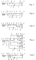
- Fig. 1 representative of the ignition voltage source, only its last part, namely the ignition coil 1, is shown.
- a discharge path 3 connects to the secondary side 2 of the ignition coil 1 and ultimately leads to the ground 4.
- An ignition distributor 9 and a spark plug 6 are provided in series in the manner shown in the discharge path.
- a line 7 is now connected to the secondary side 2 of the ignition coil 1, which also leads to ground 4 or in any case to the opposite pole of the spark plug 6.
- the capacitor 8 is arranged, which bridges all spark gaps in the discharge gap 3, i.e. the Spark gap of the distributor 9 and the spark plug 6.
- Fig. 2 differs from the circuit of FIG. 1 only in that an afterburner ignition 5 is additionally provided in the discharge path 3, as is used in multi-cylinder engines with exhaust gas afterburning.
- the line 7 bridges the afterburner 5, the ignition distributor 9 and the respective spark plug 6. It is a simplified diagram of a four-cylinder or a six-cylinder engine.
- the circuit according to FIG. 3 is constructed similarly to that according to FIG. 2.
- the discharge path 3 with the afterburner ignition 5, the distributor 9 and the spark plug 6 is therefore again provided.
- the line 7 with the capacitor 8 is arranged, which leads from the branch point 10 on the discharge path 3 to the ground 4.
- a bypass line 11 is provided, which starts from a branch point 12 between the distributor 9 and the spark plug 6 and is routed parallel to the ground 4.
- a further capacitor 13 is arranged in this bypass line 11.
- the capacitor 13 serves only to bypass the spark plug 6.
- the capacitors 8 and 13 are expediently matched to one another. For example, they can have the same design.
- Fig. 4 shows the circuit diagram for a four-cylinder engine, the ignition system is additionally suppressed.
- the suppression resistor 14 is provided here, which is arranged between the secondary side 2 of the ignition coil 1 and the branch point 10 of the line 7.
- the distributor 9 is shown here in somewhat more detail. It can also be seen that a further capacitor 13, each with a further bypass line 11, is provided for each of the four spark plugs 6. An afterburner is not provided here, for example.
Landscapes
- Engineering & Computer Science (AREA)
- Chemical & Material Sciences (AREA)
- Combustion & Propulsion (AREA)
- Mechanical Engineering (AREA)
- General Engineering & Computer Science (AREA)
- Ignition Installations For Internal Combustion Engines (AREA)
Description
- Die Erfindung bezieht sich auf eine Zündeinrichtung für Brennkraftmaschinen, Öl- und Gasbrenner u. dgl., mit einer eine Zündspule aufweisenden Zündspannungsquelle, wobei an die Sekundärseite der Zündspule mindestens eine Entladungsstrecke angeschlossen ist, in der ein Zündverteiler und mindestens eine Zündkerze vorgesehen sind. Es versteht sich, daß der Zündverteiler bei Mehrzylindermotoren im Zusammenhang mit einer entsprechenden Anzahl von Zündkerzen Anwendung findet. Je nach dem gerade gezündeten Zylinder ergibt sich dann jeweils eine Entladungsstrecke, in der der Zündverteiler und die jeweilige Zündkerze vorgesehen sind.
- Aus der DE-A-1 902199 ist ein Zündkerzenstecker bekannt, bei dem die Umhüllung, das Hohlelement und das dazwischenliegende Dielektrikum einen Kondensator bilden und bei denen der Kondensator parallel zu den Zündkerzenelektroden derart geschaltet ist, daß in dem Parallelkreis keine Widerstände eingeschlossen sind. Damit wird die Zündleistung der Zündanlage derart verbessert, daß eine Intensivierung des Zündfunkens stattfindet und somit eine bessere Verbrennung des Kraftstoff-Luft-Gemisches resultiert. Von dem Kondensator wird lediglich die Zündkerze örtlich überbrückt, so daß sich die anderen, sekundärseitig vorgesehenen Widerstände weiterhin nachteilig auswirken.
- Die US-A-3 361 932 zeigt eine Zündeinrichtung ohne Verteiler und einen Leitungsteil, in welchem ausschließlich ein Kondensator angeordnet ist, also keine zusätzlichen Widerstände. Dafür ist aber in dem anderen Teil der Leitung neben der Zündkerze noch ein Kontrollspalt als Unterbrechungsstelle vorgesehen, der selbst einen erheblichen Widerstand darstellt.
- In der Literaturstelle Bosch »Technische Unterrichtung Batteriezündung (SZ)« ist darauf hingewiesen, daß als Kondensator wirkende Teile der (ohnehin vorhandenen) Zündschaltung, beispielsweise Zündleitung gegen Masse die Zündenergie vermindern. Ein parallel zu den Zündkerzenelektroden angebrachter Kondensator ist nicht vorhanden. Es ist aber weder in der Textstelle angedeutet, noch möglich, beispielsweise die Zündleitung als Kondensator zu benutzen, also eine wesentliche Speicherung zu erzielen.
- Der Erfindung liegt die Aufgabe zugrunde, eine Zündeinrichtung der eingangs beschriebenen Art derart zu verbessern, daß die Verbrennung wirtschaftlicher abläuft und die entstehenden toxischen Abgase reduziert werden.
- Erfindungsgemäß wird dies dadurch erreicht, daß an die Sekundärseite der Zündspule eine sämtliche Unterbrechungsstellen in der Entladungsstrecke, also den Zündverteiler und die Zündkerze überbrückende Leitung parallel angeschlossen und in dieser Leitung ein Kondensator angeordnet ist, und daß weder in der Leitung noch in dem parallelen Teil der Entladungsstrekke zusätzliche Widerstände vorgesehen sind. Die Erfindung geht damit von dem Gedanken aus, die gesamte Zündeinrichtung zu verbessern, einen insgesamt höheren Zündstrom an der Zündkerze zur Wirkung zu bringen, und zwar bei vorgegebener Zündspannungsquelle mit Zündspule, um dadurch eine verstärkte Initialzündung des Kraftstoff-Luft-Gemisches zu erzielen. Wesentlich ist, daß sämtliche Unterbrechungsstellen in der Entladungsstrecke, die dort vorgesehen sind, von der Leitung überbrückt werden, also der Zündverteiler und die Zündkerze. In dieser Leitung ist dann erfindungsgemäß ein Kondensator angeordnet. Wesentlich ist weiterhin, daß weder in dieser Leitung noch im parallelen Teil der Entladungsstrecke zusätzliche Widerstände vorgesehen sind, wobei unter dem Begriff »zusätzliche Widerstände« solche Widerstände verstanden werden, die zusätzlich zu dem ohnehin einen geringen Widerstand bildenden Zündverteiler und der Zündkerze vorgesehen sein könnten. Der parallel zu der Entladungsstrecke angeordnete Kondensator wird nach der allerersten Zündung mit einer Spannung aufgeladen, die sich über die bereits wieder zusammengebrochene Entladungsstrecke nicht mehr abbauen kann. Es wird also das Rückfließen des phasenverschobenen Blindstroms in die Zündspule verhindert. Beim nächstfolgenden Zündvorgang, bei dem die Ionisation an der Zündkerze wieder erfolgt, steht die Spannung des Kondensators zusätzlich zur Verfügung. Die Spannung des Kondensators wird als zusätzlicher Strom frei und aktiviert den Zündvorgang damit. Damit ist die Möglichkeit geschaffen, eine schnellere Energieabgabe an der Zündkerze zu erzielen.
- Durch die erfindungsgemäße Zündeinrichtung werden in verschiedener Hinsicht Vorteile erreicht. In jedem Falle erfolgt eine Energiestabilisierung an jeder in dem parallelen Teil Entladungsstrecke vorgesehenen Funkenstrecke. Insbesondere erfolgt dies im Bereich des Zündverteilers. Sein Übergangswiderstand wird verringert und dadurch der Energiedurchsatz erhöht. Dies wirkt sich in der Folge auch zugleich bei allen folgenden Funkenstrecken, beispielsweise an der Zündkerze positiv aus. Der Wirkungsgrad der gesamten Zündanlage wird wesentlich erhöht. Diese Erhöhung erstreckt sich auch auf die Wirkung von Funkenstrecken, die sich in einem Nachverbrennungssystem o. dgl. befinden. Die Erfindung ist unabhängig von der Art der Zündspannungsquelle, die in herkömmlicher Bauart oder als elektronische Zündanlage o. dgl. ausgebildet sein kann. Die Anordnung des alle Funkenstrecken in der Entladungstrecke überbrückenden Kondensator bringt gleichzeitig eine Entstörung, so daß in den meisten Fällen auf die Anordnung eines Entstörwiderstandes verzichtet werden kann.
- Die Zündkerzen können zusätzlich durch je eine Umgehungsleitung überbrückt sein, in der jeweils ein weiterer Kondensator angeordnet ist. Auf die Weise wird individuell eine höhere Energieeinbringung an den verschiedenen Überschlagstrecken erreicht. Es versteht sich, daß sowohl die Leitung als auch die Umgehungsleitungen jeweils an Masse enden bzw. mit dem Teil leitend verbunden sind, der mit dem Gehäuse des Zündraumes in Verbindung steht. Dies ist in aller Regel der Motor.
- In dem parallelen Teil der Entladungsstrecke kann zusätzlich auch eine Nachbrennerzündung, eine Standheizung o. dgl. eingeschaltet sein, also jeweils Einrichtungen, die einer Zündung bedürfen. Es ist dann nicht mehr erforderlich, eine gesonderte Zündanlage für derartige Einrichtungen bereitzustellen. Es kann vielmehr die ohnehin vorhandene Zündanlage einer Brennkraftmaschine hierzu vorteilhaft mitbenutzt werden. Es versteht sich, daß auch eine solche Nachbrennerzündung, eine Standheizung o. dgl. dann von der Leitung mit dem Kondensator überbrückt ist.
- Zwischen der Sekundärseite der Zündspule und dem Abzweigpunkt der den Kondensator aufweisenden Leitung kann ein Entstörwiderstand angeordnet sein. Wesentlich ist, daß dieser Entstörwiderstand nicht mit überdeckt wird, also nicht in der Leitung und auch nicht in dem parallelen Teil der Entladungsstrecke angeordnet ist.
- Bei Anwendung von mehreren Kondensatoren bzw. einem gemeinsamen Kondensator in der Leitung und weiteren Kondensatoren für jede einzelne Zündkerze können diese Kondensatoren insgesamt aufeinander abgestimmt sein.
- Ausführungsbeispiele der Erfindung werden anhand der Zeichnungen dargestellt und beschrieben. Es zeigt
- Fig. 1 eine schematische Schaltungsanordnung der Zündeinrichtung in einer ersten Ausführungsform,
- Fig. 2 eine schematische Schaltungsanordnung der Zündeinrichtung in einer zweiten Ausführungsform,
- Fig. 3 eine schematische Schaltungsanordnung der Zündeinrichtung in einer dritten Ausführungsform, '
- Fig.4 ein weiteres Ausführungsbeispiel der Zündeinrichtung für einen Vierzylindermotor und
- Fig. 5 eine schematisierte Zündeinrichtung unter Einschluß einer Nachverbrennungsanlage.
- In Fig. 1 ist stellvertretend für die Zündspannungsquelle lediglich deren letztes Teil, nämlich die Zündspule 1, dargestellt. Wie ersichtlich, schließt an die Sekundärseite 2 der Zündspule 1 eine Entladungsstrecke 3 an, die letztlich zur Masse 4 führt. In der Entladungsstrecke ist ein Zündverteiler 9 und eine Zündkerze 6 in der gezeigten Weise in Reihe geschaltet vorgesehen. Es handelt sich beispielsweise um einen Mehrzylindermotor. An die Sekundärseite 2 der Zündspule 1 ist nun eine Leitung 7 angeschlossen, die ebenfalls zur Masse 4 führt oder jedenfalls zu dem Gegenpol der Zündkerze 6. In dieser Leitung 7 ist der Kondensator 8 angeordnet, der sämtliche Funkenstrecken in der Entladungsstrecke 3 überbrückt, also die Funkenstrecke des Zündverteilers 9 und der Zündkerze 6.
- Fig. 2 unterscheidet sich von der Schaltung nach Fig. 1 nur dadurch, daß in der Entladungsstrecke 3 zusätzlich eine Nachbrennerzündung 5 vorgesehen ist, wie er bei Mehrzylindermotoren mit einer Abgasnachverbrennung angewendet wird. Hier überbrückt die Leitung 7 die Nachbrenneinrichtung 5, den Zündverteiler 9 und die jeweilige Zündkerze 6. Es handelt sich um ein vereinfachtes Schema eines Vierzylinder- oder eines Sechszylindermotors.
- Die Schaltung gemäß Fig. 3 ist ähnlich aufgebaut wie die nach Fig. 2. Es ist also wiederum die Entladungsstrecke 3 mit der Nachbrennerzündung 5, dem Zündverteiler 9 und der Zündkerze 6 vorgesehen. Parallel dazu ist die Leitung 7 mit dem Kondensator 8 angeordnet, die vom Abzweigpunkt 10 an der Entladungsstrecke 3 bis zur Masse 4 führt. Zusätzlich ist eine Umgehungsleitung 11 vorgesehen, die von einem Abzweigpunkt 12 zwischen dem Zündverteiler 9 und der Zündkerze 6 ausgeht und parallel zur Masse 4 geführt ist. In dieser Umgehungsleitung 11 ist ein weiterer Kondensator 13 angeordnet. Der Kondensator 13 dient lediglich der Überbrückung der Zündkerze 6. Die Kondensatoren 8 und 13 sind zweckmäßig aufeinander abgestimmt. Sie können beispielsweise gleich ausgebildet sein.
- Fig. 4 zeigt den Schaltplan für einen Vierzylindermotor, dessen Zündanlage zusätzlich noch entstört ist. Es ist hier der Entstörwiderstand 14 vorgesehen, der zwischen der Sekundärseite 2 der Zündspule 1 und dem Abzweigpunkt 10 der Leitung 7 angeordnet ist. Der Zündverteiler 9 ist hier etwas ausführlicher dargestellt. Ebenso ersieht man, daß für jede der vier Zündkerzen 6 ein weiterer Kondensator 13 mit je einer weiteren Umgehungsleitung 11 vorgesehen sind. Eine Nachbrenneinrichtung ist hier beispielsweise nicht vorgesehen.
- Bei der Zündeinrichtung gemäß Fig. 5 sind sämtliche Funkenstrecken durch die Leitung 7 mit dem Kondensator 8 überbrückt. Zusätzlich ist die Nachbrenneinrichtung 5 mit einer Parallelleitung 15 überbrückt, in der ein weiterer Kondensator 16 angeordnet ist. Es versteht sich, daß die Anlagen gemäß Fig. 3 und 5 auch kombiniert werden können, indem nämlich Umgehungsleitungen 11 und eine Parallelleitung 15 kombiniert werden.
Claims (5)
Priority Applications (1)
| Application Number | Priority Date | Filing Date | Title |
|---|---|---|---|
| AT80102307T ATE8169T1 (de) | 1979-05-02 | 1980-04-29 | Zuendeinrichtung fuer brennkraftmaschinen, oelund gasbrenner. |
Applications Claiming Priority (2)
| Application Number | Priority Date | Filing Date | Title |
|---|---|---|---|
| DE2917617A DE2917617C2 (de) | 1979-05-02 | 1979-05-02 | Zündeinrichtung für Brennkraftmaschinen, Öl- und Gasbrenner u. dgl. |
| DE2917617 | 1979-05-02 |
Publications (2)
| Publication Number | Publication Date |
|---|---|
| EP0018622A1 EP0018622A1 (de) | 1980-11-12 |
| EP0018622B1 true EP0018622B1 (de) | 1984-06-27 |
Family
ID=6069715
Family Applications (1)
| Application Number | Title | Priority Date | Filing Date |
|---|---|---|---|
| EP80102307A Expired EP0018622B1 (de) | 1979-05-02 | 1980-04-29 | Zündeinrichtung für Brennkraftmaschinen, Öl- und Gasbrenner |
Country Status (3)
| Country | Link |
|---|---|
| EP (1) | EP0018622B1 (de) |
| AT (1) | ATE8169T1 (de) |
| DE (1) | DE2917617C2 (de) |
Families Citing this family (3)
| Publication number | Priority date | Publication date | Assignee | Title |
|---|---|---|---|---|
| US4487192A (en) * | 1983-04-18 | 1984-12-11 | Ford Motor Co | Plasma jet ignition system |
| US4548174A (en) * | 1984-09-28 | 1985-10-22 | Ford Motor Company | Dual plug ignition system |
| EP0181961B1 (de) * | 1984-11-22 | 1988-06-29 | Bernard Hue | Impulsoszillatorzündung für Verbrennungskraftmaschinen |
Family Cites Families (9)
| Publication number | Priority date | Publication date | Assignee | Title |
|---|---|---|---|---|
| CH155574A (de) * | 1931-01-08 | 1932-06-30 | Maderna Antonio | Vorschaltfunkenstrecke zum Vergrössern der Intensität der Zündfunken von Verbrennungsmotoren. |
| CH173500A (de) * | 1932-12-28 | 1934-11-30 | Bosch Robert Ag | Einrichtung zur Verhinderung der Ausstrahlung elektromagnetischer Wellen an Zündanlagen für Verbrennungsmotoren. |
| GB1077004A (en) * | 1963-05-01 | 1967-07-26 | Rotax Ltd | Spark ignition apparatus |
| US3324350A (en) * | 1964-03-27 | 1967-06-06 | Bendix Corp | Electrical sparking system |
| DE1902199C3 (de) * | 1969-01-17 | 1975-06-05 | Heinz 3414 Hardegsen Baur | Zündkerzenstecker |
| GB1334230A (en) * | 1970-01-29 | 1973-10-17 | Lucas Industries Ltd | Spark ignition systems for internaal combustion engines |
| DE2363804A1 (de) * | 1973-12-21 | 1975-06-26 | Uwe Holtin | Kondensatorzuendkerze |
| DE2554517A1 (de) * | 1974-12-26 | 1976-07-08 | Ford Werke Ag | Zuendkerze fuer verbrennungsmotoren |
| JPS59706B2 (ja) * | 1978-03-03 | 1984-01-07 | 林精鋼株式会社 | ガソリンエンヂンに於けるスパ−クの強化装置 |
-
1979
- 1979-05-02 DE DE2917617A patent/DE2917617C2/de not_active Expired
-
1980
- 1980-04-29 EP EP80102307A patent/EP0018622B1/de not_active Expired
- 1980-04-29 AT AT80102307T patent/ATE8169T1/de not_active IP Right Cessation
Non-Patent Citations (1)
| Title |
|---|
| BOSCH TECHNISCHE UNTERRICHTUNG -VDT-UBE 120/3 * |
Also Published As
| Publication number | Publication date |
|---|---|
| EP0018622A1 (de) | 1980-11-12 |
| ATE8169T1 (de) | 1984-07-15 |
| DE2917617A1 (de) | 1980-11-13 |
| DE2917617C2 (de) | 1984-04-19 |
Similar Documents
| Publication | Publication Date | Title |
|---|---|---|
| DE4241471C2 (de) | Verbrennungsermittlungsvorrichtung für eine Brennkraftmaschine | |
| DE4133049C2 (de) | Zündvorrichtung für Verbrennungsmotoren | |
| EP0892172A2 (de) | Verfahren zum Betrieb einer direkteinspritzenden Otto-Brennkraftmaschine | |
| DE2927058C2 (de) | Steuereinrichtung für eine Zündspule | |
| EP0157006B1 (de) | Mehrkerzige und verteilerlose Zündanlage für Brennkraftmaschinen | |
| DE2823391C2 (de) | ||
| DE2607278A1 (de) | Zuendkerze fuer verbrennungsmotoren | |
| DE3314157A1 (de) | Anregungskreis fuer lasersysteme, insbesondere fuer te-hochenergielaser, mit einstellung der vorionisierung | |
| DE4239803C2 (de) | Ionisationsstromdetektoreinrichtung für eine Brennkraftmaschine | |
| DE2917617C2 (de) | Zündeinrichtung für Brennkraftmaschinen, Öl- und Gasbrenner u. dgl. | |
| DE3441997A1 (de) | Zuendkerze fuer eine brennkraftmaschine | |
| DE2652541A1 (de) | Elektronisches zuendsystem fuer brennkraftmaschinen | |
| DE4117808C2 (de) | Zündanlagen für Brennkraftmaschinen mit Hochspannungsschalter | |
| DE3515526A1 (de) | Kontaktlose zuendanlage | |
| DE2811049A1 (de) | Zuendsystem fuer einen verbrennungsmotor | |
| EP0591686A2 (de) | Verbindungsteil einer Zündanlage | |
| DE1182473B (de) | Verteiler- und unterbrecherlose Zuendanlage fuer Mehrzylinderbrennkraftmaschinen | |
| DE69428626T2 (de) | Ionisierungsfühler für Verbrennungsmotoren | |
| DE383504C (de) | Funkenpruefer fuer Explosionsmotoren | |
| EP0181961A1 (de) | Impulsoszillatorzündung für Verbrennungskraftmaschinen | |
| DE3145169A1 (de) | "anordnung zur erzielung von hochspannung" | |
| DE2259378C3 (de) | Schutzschaltung für elektrische Zunder | |
| DE2612695B2 (de) | Schaltungsanordnung | |
| DE2319670A1 (de) | Verfahren und einrichtung zur abgasentgiftung von brennkraftmaschinen | |
| DE10010753C2 (de) | Vorrichtung zur Zündung eines Brennstoffgemisches eines Kraftfahrzeugmotors |
Legal Events
| Date | Code | Title | Description |
|---|---|---|---|
| PUAI | Public reference made under article 153(3) epc to a published international application that has entered the european phase |
Free format text: ORIGINAL CODE: 0009012 |
|
| AK | Designated contracting states |
Designated state(s): AT CH NL |
|
| 17P | Request for examination filed |
Effective date: 19810508 |
|
| GRAA | (expected) grant |
Free format text: ORIGINAL CODE: 0009210 |
|
| AK | Designated contracting states |
Designated state(s): AT CH LI NL |
|
| REF | Corresponds to: |
Ref document number: 8169 Country of ref document: AT Date of ref document: 19840715 Kind code of ref document: T |
|
| PLBE | No opposition filed within time limit |
Free format text: ORIGINAL CODE: 0009261 |
|
| STAA | Information on the status of an ep patent application or granted ep patent |
Free format text: STATUS: NO OPPOSITION FILED WITHIN TIME LIMIT |
|
| 26N | No opposition filed | ||
| PGFP | Annual fee paid to national office [announced via postgrant information from national office to epo] |
Ref country code: CH Payment date: 19920428 Year of fee payment: 13 |
|
| PGFP | Annual fee paid to national office [announced via postgrant information from national office to epo] |
Ref country code: AT Payment date: 19920429 Year of fee payment: 13 |
|
| PGFP | Annual fee paid to national office [announced via postgrant information from national office to epo] |
Ref country code: NL Payment date: 19920430 Year of fee payment: 13 |
|
| PG25 | Lapsed in a contracting state [announced via postgrant information from national office to epo] |
Ref country code: AT Effective date: 19930429 |
|
| PG25 | Lapsed in a contracting state [announced via postgrant information from national office to epo] |
Ref country code: LI Effective date: 19930430 Ref country code: CH Effective date: 19930430 |
|
| PG25 | Lapsed in a contracting state [announced via postgrant information from national office to epo] |
Ref country code: NL Effective date: 19931101 |
|
| NLV4 | Nl: lapsed or anulled due to non-payment of the annual fee | ||
| REG | Reference to a national code |
Ref country code: CH Ref legal event code: PL |