EP0017829B1 - Kreiselpumpe und ihr Gehäuse - Google Patents
Kreiselpumpe und ihr Gehäuse Download PDFInfo
- Publication number
- EP0017829B1 EP0017829B1 EP80101683A EP80101683A EP0017829B1 EP 0017829 B1 EP0017829 B1 EP 0017829B1 EP 80101683 A EP80101683 A EP 80101683A EP 80101683 A EP80101683 A EP 80101683A EP 0017829 B1 EP0017829 B1 EP 0017829B1
- Authority
- EP
- European Patent Office
- Prior art keywords
- duct
- chamber
- rotor
- rotary pump
- shaft
- Prior art date
- Legal status (The legal status is an assumption and is not a legal conclusion. Google has not performed a legal analysis and makes no representation as to the accuracy of the status listed.)
- Expired
Links
- 230000003467 diminishing effect Effects 0.000 claims 1
- 238000004804 winding Methods 0.000 claims 1
- 239000007788 liquid Substances 0.000 abstract description 15
- 238000011144 upstream manufacturing Methods 0.000 abstract description 3
- 230000003247 decreasing effect Effects 0.000 abstract 1
- 230000010355 oscillation Effects 0.000 abstract 1
- 230000002035 prolonged effect Effects 0.000 abstract 1
- 239000007787 solid Substances 0.000 abstract 1
- 238000004519 manufacturing process Methods 0.000 description 5
- 239000002184 metal Substances 0.000 description 2
- 239000000126 substance Substances 0.000 description 2
- 238000010009 beating Methods 0.000 description 1
- 238000005266 casting Methods 0.000 description 1
- 230000007423 decrease Effects 0.000 description 1
- 239000011521 glass Substances 0.000 description 1
- 239000003673 groundwater Substances 0.000 description 1
- 230000002401 inhibitory effect Effects 0.000 description 1
- 238000012423 maintenance Methods 0.000 description 1
- 239000000463 material Substances 0.000 description 1
- 238000005086 pumping Methods 0.000 description 1
- 230000000630 rising effect Effects 0.000 description 1
- 238000009423 ventilation Methods 0.000 description 1
- 238000013022 venting Methods 0.000 description 1
Images
Classifications
-
- F—MECHANICAL ENGINEERING; LIGHTING; HEATING; WEAPONS; BLASTING
- F04—POSITIVE - DISPLACEMENT MACHINES FOR LIQUIDS; PUMPS FOR LIQUIDS OR ELASTIC FLUIDS
- F04D—NON-POSITIVE-DISPLACEMENT PUMPS
- F04D29/00—Details, component parts, or accessories
- F04D29/40—Casings; Connections of working fluid
- F04D29/42—Casings; Connections of working fluid for radial or helico-centrifugal pumps
- F04D29/44—Fluid-guiding means, e.g. diffusers
- F04D29/445—Fluid-guiding means, e.g. diffusers especially adapted for liquid pumps
-
- E—FIXED CONSTRUCTIONS
- E04—BUILDING
- E04D—ROOF COVERINGS; SKY-LIGHTS; GUTTERS; ROOF-WORKING TOOLS
- E04D13/00—Special arrangements or devices in connection with roof coverings; Protection against birds; Roof drainage ; Sky-lights
- E04D13/04—Roof drainage; Drainage fittings in flat roofs, balconies or the like
- E04D13/08—Down pipes; Special clamping means therefor
-
- F—MECHANICAL ENGINEERING; LIGHTING; HEATING; WEAPONS; BLASTING
- F04—POSITIVE - DISPLACEMENT MACHINES FOR LIQUIDS; PUMPS FOR LIQUIDS OR ELASTIC FLUIDS
- F04D—NON-POSITIVE-DISPLACEMENT PUMPS
- F04D29/00—Details, component parts, or accessories
- F04D29/40—Casings; Connections of working fluid
- F04D29/42—Casings; Connections of working fluid for radial or helico-centrifugal pumps
- F04D29/426—Casings; Connections of working fluid for radial or helico-centrifugal pumps especially adapted for liquid pumps
- F04D29/4266—Casings; Connections of working fluid for radial or helico-centrifugal pumps especially adapted for liquid pumps made of sheet metal
Definitions
- the invention relates to a centrifugal pump, in particular one with a rotor, which is accommodated in a working space which is provided in order to be at least partially immersed in the liquid to be conveyed.
- a centrifugal pump in particular one with a rotor
- Such pumps are known in large numbers and serve a variety of purposes, from pumping out the groundwater to lifting chemicals from drums and other vessels. Since this type of flooded pump with a drive motor generally arranged above the liquid level usually consists of a few parts, places little demands on the seals and is accordingly low-maintenance, it is used primarily wherever dirty or aggressive media are to be pumped, and also where cheapness of manufacture and extremely long, trouble-free operation are important. Both require an acceptable level of efficiency at a relatively low number of revolutions, such as that provided by a shaded-pole motor coupled directly to the shaft of the impeller cheaply and reliably.
- the type of pumps mentioned at the outset is particularly suitable for use as so-called barrel pumps that can be lowered into a container, it is also desirable to keep the outer dimensions of the pump body as small as possible so that the pump can be lowered through a narrow opening in a container.
- a further pump is described in German design specification 1.155.677, in which the rotor rotates in a working space delimited by a cylindrical outer surface concentric with the rotor axis. From there, the liquid, which is set in rotation, passes through a worm gear into a venting chamber, which it leaves again through a pressure port attached tangentially to it.
- Such a pump is too bulky for the tasks provided here, and the shape of the ventilation space with the pressure connector attached to it also requires the production of relatively complex castings.
- the U.S. Patent 2,618,223 proposes a simpler pump which is particularly easy to manufacture from metal strips welded together in a bent form.
- the aim of the invention is to create a pump of the type mentioned at the outset which avoids these disadvantages and at the same time can be built as compactly as possible.
- the invention proposes a pump with a rotor which rotates in a working space which is delimited by a circumferential surface which is essentially concentric with the axis of rotation of the rotor, one end face of which is connected to the outlet line of the pump, entirely within that parallel to the axis of rotation
- Certain largest clear width of the working space begins worm gear, which winds around this axis with a progressively smaller radius, and the first section of which forms an opening that is open towards the side of the working space, which is characterized in that the worm gear is viewed in the direction of flow at the same time winds around the turning axis of the rotor with an increasingly greater slope until it runs essentially parallel to it.
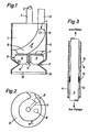
- FIG. 1 denotes an essentially cylindrical base body or stator, for example made of plastic, on the upper end of which a pressure line 2 and a guide tube 4 containing the drive shaft 3 are screwed.
- An electric motor (not shown) acts on the upper end of the shaft 3, while the rotor 5 is mounted on its lower end. The sense of rotation of the same is indicated by the arrow F in FIG. 2.
- the lower bearing of the shaft 3 is formed by its passage through the stator; since this bearing is lubricated by the liquid to be pumped, it can have a relatively large clearance, for example 3/10 mm. As described further below, the liquid contained therein can optionally also be placed under a slight excess pressure.
- the rotor 5 forms an impeller with four flat blades 6, which are parallel to the shaft 3 and which are fastened to an overhead, round base plate 7.
- the wings 6 are beveled at their lower, outer circumference at an angle ⁇ of approximately 30 ° -50 °.
- a helical passage 8 is recessed, which - seen in the direction of flow, that is, in the direction of arrow G - leads from the periphery of the working space surrounding the impeller to the pressure line 2.
- the radius of the worm measured from shaft 3 progressively decreases, while at the same time the pitch of the worm parallel to shaft 3 increases progressively until it becomes infinite at the upper mouth of the worm gear, so that it slants without kinks into the line parallel to the shaft .
- this passage if milled out of the base body, will be open to the outside, i.e. below point L in FIG. 1 can only be completed radially outwards when the sleeve 9 provided in this embodiment surrounds the base body.
- This sleeve also limits the working space surrounding the impeller and occasionally forms the intake port 10 of the pump. It can also, in a manner not shown, be extended upwards and be designed as a support tube for the entire pump. In other manufacturing processes, however, the aisle can also be enclosed on all sides in the base body from its outlet opening into the pressure line 2 to its opposite junction in the periphery of the working space. In the lower mouth area, the course of which can be seen clearly from FIG.
- the part of the passage cut out of the base body tapers and forms only a tapering channel. If one imagines this to be a passageway with a reasonably constant cross-section, then this would ultimately lie almost entirely in the working space, from which the helical passageway is not separated in its upstream estuary. In this part, which is open on the side, together with the depth of the gutter recessed from the base body, the incline of the corridor, which is thought to be a full cross-section, drops to almost zero.
- This open part which in FIG. 2 extends almost over 360 °, will preferably not extend over less than about 180 ° and will flow evenly into the work area.
- the whole aisle should of course be as free of kinks as possible.
- the presence of a base body is not necessary, since the aisle e.g. can also be formed by a suitably fastened tube which is wound into a screw.
- the sleeve 9 made of sheet metal in the described embodiment is pushed over the base body and fastened to it. It is constricted at point 11, at the same angle as the impeller. Below it, it expands again and carries an intake filter 12 at its lower end 10.
- the sleeve on the constriction 11 is closed on the end face, as indicated by the dash-dotted line A.
- the suction can then take place through one or more through bores in the base body, which connect the working space with the outside space around the pump without touching the screw flight.
- Such a bore is shown in dash-dotted lines in FIG. 2 and is designated by B.
- the suction on the top of the stator that this enables can be advantageous.
- FIG. 3 shows a section of the shaft 3 leading from the impeller 5 to the drive motor (not shown). This is guided loosely, for example with a play of 1/2 mm, in the guide tube 4.
- the space 13 between the shaft and the tube will be at least partially filled with the liquid to be pumped during operation of the pump, due to the excess pressure existing in the upper part of the working space and the aforementioned loose mounting of the shaft in the base body.
- the pressure of the liquid in the intermediate space 13 can be achieved by attaching a pressure duct D (FIGS. 1 and 2), which has a high pressure point in the screw passage the space surrounding the wave can be increased.
- a flow-inhibiting baffle 14 is advantageously provided in the upper part of the guide tube 4 and the guide tube itself above it with a backflow opening 15 provided.
- the play between the shaft and the chicane can be, for example, approximately 0.2 mm, which is sufficient to allow an increased, shock-absorbing excess pressure to arise in the space below.
Landscapes
- Engineering & Computer Science (AREA)
- Mechanical Engineering (AREA)
- General Engineering & Computer Science (AREA)
- Architecture (AREA)
- Civil Engineering (AREA)
- Structural Engineering (AREA)
- Structures Of Non-Positive Displacement Pumps (AREA)
- Iron Core Of Rotating Electric Machines (AREA)
- Preparation Of Compounds By Using Micro-Organisms (AREA)
Priority Applications (1)
| Application Number | Priority Date | Filing Date | Title |
|---|---|---|---|
| AT80101683T ATE7946T1 (de) | 1979-04-09 | 1980-03-28 | Kreiselpumpe und ihr gehaeuse. |
Applications Claiming Priority (2)
| Application Number | Priority Date | Filing Date | Title |
|---|---|---|---|
| CH3327/79 | 1979-04-09 | ||
| CH332779A CH643918A5 (de) | 1979-04-09 | 1979-04-09 | Kreiselpumpe. |
Publications (2)
| Publication Number | Publication Date |
|---|---|
| EP0017829A1 EP0017829A1 (de) | 1980-10-29 |
| EP0017829B1 true EP0017829B1 (de) | 1984-06-13 |
Family
ID=4253569
Family Applications (1)
| Application Number | Title | Priority Date | Filing Date |
|---|---|---|---|
| EP80101683A Expired EP0017829B1 (de) | 1979-04-09 | 1980-03-28 | Kreiselpumpe und ihr Gehäuse |
Country Status (8)
| Country | Link |
|---|---|
| US (1) | US4349311A (enExample) |
| EP (1) | EP0017829B1 (enExample) |
| JP (1) | JPS55139998A (enExample) |
| AT (1) | ATE7946T1 (enExample) |
| CH (1) | CH643918A5 (enExample) |
| DE (1) | DE3013138A1 (enExample) |
| DK (1) | DK148105C (enExample) |
| NO (1) | NO151979C (enExample) |
Families Citing this family (5)
| Publication number | Priority date | Publication date | Assignee | Title |
|---|---|---|---|---|
| FR2516987B1 (fr) * | 1981-11-23 | 1986-08-14 | Peugeot | Pompe rotative, notamment pour liquide de refroidissement d'un moteur a combustion interne |
| US4448573A (en) * | 1982-03-25 | 1984-05-15 | General Electric Company | Single-stage, multiple outlet centrifugal blower |
| DE3814721A1 (de) * | 1988-04-30 | 1989-11-09 | Asea Brown Boveri | Radialluefter mit integriertem schmutzabscheider |
| DE4041545A1 (de) * | 1990-02-21 | 1991-08-22 | Klein Schanzlin & Becker Ag | Kreiselpumpe |
| CN103016361B (zh) * | 2012-12-12 | 2015-05-13 | 君禾泵业股份有限公司 | 低吸水水泵 |
Family Cites Families (24)
| Publication number | Priority date | Publication date | Assignee | Title |
|---|---|---|---|---|
| US406394A (en) * | 1889-07-02 | Joseph j | ||
| US11544A (en) * | 1854-08-22 | William | ||
| US976565A (en) * | 1909-11-22 | 1910-11-22 | El Campo Machine Company | Well-pumping mechanism. |
| CH95098A (de) * | 1921-05-09 | 1922-06-16 | Bucher Guyer J | Zentrifugal-Jauchepumpe. |
| FR676564A (fr) * | 1929-06-12 | 1930-02-25 | Ventilateur | |
| US2007856A (en) * | 1934-03-16 | 1935-07-09 | Haldeman James Fred | Fountain |
| FR831864A (fr) * | 1937-04-15 | 1938-09-15 | Neu Sa | Perfectionnement apporté aux ventilateurs hélico-centrifuges |
| US2331641A (en) * | 1941-01-21 | 1943-10-12 | Jack E Walker | Shaft sealing means for pumps |
| CH243663A (de) * | 1944-12-16 | 1946-07-31 | Flueck Hans | Zentrifugalpumpe. |
| US2445182A (en) * | 1946-11-01 | 1948-07-13 | Deming Co | Means for connecting a driving motor to the shaft of a rotary pump |
| GB673062A (en) * | 1947-12-31 | 1952-06-04 | Sfindex | Improvements in guiding means for annular flow of fluids |
| US2618223A (en) * | 1948-10-21 | 1952-11-18 | Ransohoff Inc N | Centrifugal pump housing |
| US2910946A (en) * | 1953-01-17 | 1959-11-03 | Ask Emil Julius | Pumps |
| DE1026475B (de) * | 1955-02-24 | 1958-03-20 | Realisations Ind Fournier & Mo | Halbaxialluefter mit axial radialer Austrittsspirale und mit kegeliger Laufradnabe |
| US2930325A (en) * | 1958-05-09 | 1960-03-29 | William D Beard | Elevated discharge sump pump |
| DE1155677B (de) * | 1960-01-14 | 1963-10-10 | Ernst Van Gerfsheim | Selbstansaugende Kreiselpumpe fuer Schmutz- und Abwaesser mit einer unterhalb des Druckstutzens angeordneten Fuell- und Entlueftungskammer |
| GB986339A (en) * | 1963-12-22 | 1965-03-17 | Robert Mortimer Penney | Centrifugal pump |
| GB1041935A (en) * | 1964-08-31 | 1966-09-07 | Miklos Patay | Improvements in centrifugal pumps |
| CH450925A (de) * | 1965-07-30 | 1968-05-15 | Flux Geraete Gmbh | Pumpe, insbesondere Fasspumpe |
| GB1352209A (en) * | 1971-11-30 | 1974-05-08 | Bp Chem Int Ltd | Submersible pump |
| FR2169496A5 (enExample) * | 1972-01-28 | 1973-09-07 | Sodery | |
| GB1406827A (en) * | 1972-11-08 | 1975-09-17 | Reid K D | Mounting of rotatable impeller shafts |
| DE2307060C3 (de) * | 1973-02-13 | 1980-06-26 | Siemens Ag, 1000 Berlin Und 8000 Muenchen | Eintauchpumpe |
| NL7708887A (en) * | 1977-08-11 | 1979-02-13 | Stork Koninklijke Maschf | Pump with axial flow impeller - has tangential branch on housing above impeller forming outlet |
-
1979
- 1979-04-09 CH CH332779A patent/CH643918A5/de not_active IP Right Cessation
-
1980
- 1980-03-28 AT AT80101683T patent/ATE7946T1/de not_active IP Right Cessation
- 1980-03-28 US US06/135,089 patent/US4349311A/en not_active Expired - Lifetime
- 1980-03-28 EP EP80101683A patent/EP0017829B1/de not_active Expired
- 1980-04-01 DK DK140280A patent/DK148105C/da not_active IP Right Cessation
- 1980-04-03 DE DE19803013138 patent/DE3013138A1/de active Granted
- 1980-04-08 NO NO801003A patent/NO151979C/no unknown
- 1980-04-09 JP JP4671780A patent/JPS55139998A/ja active Pending
Also Published As
| Publication number | Publication date |
|---|---|
| NO801003L (no) | 1980-10-10 |
| DE3013138A1 (de) | 1980-10-23 |
| DE3013138C2 (enExample) | 1992-02-13 |
| US4349311A (en) | 1982-09-14 |
| JPS55139998A (en) | 1980-11-01 |
| DK148105B (da) | 1985-03-04 |
| ATE7946T1 (de) | 1984-06-15 |
| DK140280A (da) | 1980-10-10 |
| EP0017829A1 (de) | 1980-10-29 |
| DK148105C (da) | 1989-11-20 |
| CH643918A5 (de) | 1984-06-29 |
| NO151979B (no) | 1985-04-01 |
| NO151979C (no) | 1985-07-10 |
Similar Documents
| Publication | Publication Date | Title |
|---|---|---|
| DE69005510T2 (de) | Pumpe um Gas von einer zu pumpenden Flüssigkeit abzutrennen. | |
| DE1628335A1 (de) | Radialventilator mit axialer Ausstroemung | |
| DE2223087A1 (de) | Fluegelzellenverdichter | |
| EP2188532B1 (de) | Pumpenlaufrad und pumpe umfassend ein derartiges pumpenlaufrad | |
| DE102012216196A1 (de) | Pumpe | |
| DE4428633A1 (de) | Kraftstoffpumpe zum Zuführen von Kraftstoff zu einem Fahrzeugmotor | |
| DE7507522U (de) | Kreiselpumpe | |
| EP0017829B1 (de) | Kreiselpumpe und ihr Gehäuse | |
| DE4338931C2 (de) | Verstopfungsfreie Kreiselpumpe | |
| WO2000047899A1 (de) | Seitenkanalpumpe | |
| DE69307835T2 (de) | Pumpengehäuse Vorrichtung | |
| DE69119765T2 (de) | Pumpe mit spiralförmigen schaufeln | |
| DE19513962B4 (de) | Radiale Kreiselpumpe | |
| DE4039712C2 (de) | Peripheralpumpe | |
| DE69106779T2 (de) | Einstufige Kreiselpumpe mit einem peripherisch-axialen Diffusor. | |
| DE2024215C3 (de) | Schaumpumpe | |
| DE2903277A1 (de) | Schraubenpumpe, insbesondere zur foerderung von abwasser u.dgl. | |
| DE4239071A1 (de) | Tauchpumpenaggregat | |
| EP2990651B1 (de) | Pumpengehäuse | |
| DE3211230A1 (de) | Kreiselpumpe, insbesondere fuer schmutz- und abwasser | |
| DE2924822C2 (de) | Schneckenzentrifugal-Verdrängerpumpe | |
| DE957097C (de) | Selbstansaugende Fluegelradpumpe | |
| DE20304488U1 (de) | Flüssigkeitsbetriebene, geschwindigkeitserhöhende Vorrichtung | |
| DE69903904T2 (de) | Waagerechte selbstansaugende Pumpe mit axialem Einlass | |
| DE69312629T2 (de) | Pumpe mit axialem Förderstrom |
Legal Events
| Date | Code | Title | Description |
|---|---|---|---|
| PUAI | Public reference made under article 153(3) epc to a published international application that has entered the european phase |
Free format text: ORIGINAL CODE: 0009012 |
|
| AK | Designated contracting states |
Designated state(s): AT BE FR GB IT NL SE |
|
| 17P | Request for examination filed |
Effective date: 19810409 |
|
| ITCL | It: translation for ep claims filed |
Representative=s name: FUMERO BREVETTI S.N.C. |
|
| ITF | It: translation for a ep patent filed | ||
| GRAA | (expected) grant |
Free format text: ORIGINAL CODE: 0009210 |
|
| AK | Designated contracting states |
Designated state(s): AT BE FR GB IT NL SE |
|
| REF | Corresponds to: |
Ref document number: 7946 Country of ref document: AT Date of ref document: 19840615 Kind code of ref document: T |
|
| ET | Fr: translation filed | ||
| PLBE | No opposition filed within time limit |
Free format text: ORIGINAL CODE: 0009261 |
|
| STAA | Information on the status of an ep patent application or granted ep patent |
Free format text: STATUS: NO OPPOSITION FILED WITHIN TIME LIMIT |
|
| 26N | No opposition filed | ||
| PGFP | Annual fee paid to national office [announced via postgrant information from national office to epo] |
Ref country code: SE Payment date: 19910228 Year of fee payment: 12 |
|
| PGFP | Annual fee paid to national office [announced via postgrant information from national office to epo] |
Ref country code: GB Payment date: 19910304 Year of fee payment: 12 |
|
| PGFP | Annual fee paid to national office [announced via postgrant information from national office to epo] |
Ref country code: AT Payment date: 19910319 Year of fee payment: 12 |
|
| PGFP | Annual fee paid to national office [announced via postgrant information from national office to epo] |
Ref country code: FR Payment date: 19910320 Year of fee payment: 12 |
|
| PGFP | Annual fee paid to national office [announced via postgrant information from national office to epo] |
Ref country code: BE Payment date: 19910321 Year of fee payment: 12 |
|
| ITTA | It: last paid annual fee | ||
| PGFP | Annual fee paid to national office [announced via postgrant information from national office to epo] |
Ref country code: NL Payment date: 19910331 Year of fee payment: 12 |
|
| PG25 | Lapsed in a contracting state [announced via postgrant information from national office to epo] |
Ref country code: GB Effective date: 19920328 Ref country code: AT Effective date: 19920328 |
|
| PG25 | Lapsed in a contracting state [announced via postgrant information from national office to epo] |
Ref country code: SE Effective date: 19920329 |
|
| PG25 | Lapsed in a contracting state [announced via postgrant information from national office to epo] |
Ref country code: BE Effective date: 19920331 |
|
| BERE | Be: lapsed |
Owner name: MILZ ARTHUR Effective date: 19920331 |
|
| PG25 | Lapsed in a contracting state [announced via postgrant information from national office to epo] |
Ref country code: NL Effective date: 19921001 |
|
| NLV4 | Nl: lapsed or anulled due to non-payment of the annual fee | ||
| GBPC | Gb: european patent ceased through non-payment of renewal fee | ||
| PG25 | Lapsed in a contracting state [announced via postgrant information from national office to epo] |
Ref country code: FR Effective date: 19921130 |
|
| REG | Reference to a national code |
Ref country code: FR Ref legal event code: ST |
|
| EUG | Se: european patent has lapsed |
Ref document number: 80101683.3 Effective date: 19921005 |