EP0016866B1 - Dispositif pour rendre ineffectives les différences de tension de sortie d'un transformateur de pression dans des appareils à bande magnétique, causées par des fluctuations de température - Google Patents
Dispositif pour rendre ineffectives les différences de tension de sortie d'un transformateur de pression dans des appareils à bande magnétique, causées par des fluctuations de température Download PDFInfo
- Publication number
- EP0016866B1 EP0016866B1 EP79105148A EP79105148A EP0016866B1 EP 0016866 B1 EP0016866 B1 EP 0016866B1 EP 79105148 A EP79105148 A EP 79105148A EP 79105148 A EP79105148 A EP 79105148A EP 0016866 B1 EP0016866 B1 EP 0016866B1
- Authority
- EP
- European Patent Office
- Prior art keywords
- pressure transducer
- temperature
- output
- magnetic tape
- voltage
- Prior art date
- Legal status (The legal status is an assumption and is not a legal conclusion. Google has not performed a legal analysis and makes no representation as to the accuracy of the status listed.)
- Expired
Links
Images
Classifications
-
- G—PHYSICS
- G11—INFORMATION STORAGE
- G11B—INFORMATION STORAGE BASED ON RELATIVE MOVEMENT BETWEEN RECORD CARRIER AND TRANSDUCER
- G11B15/00—Driving, starting or stopping record carriers of filamentary or web form; Driving both such record carriers and heads; Guiding such record carriers or containers therefor; Control thereof; Control of operating function
- G11B15/56—Driving, starting or stopping record carriers of filamentary or web form; Driving both such record carriers and heads; Guiding such record carriers or containers therefor; Control thereof; Control of operating function the record carrier having reserve loop, e.g. to minimise inertia during acceleration measuring or control in connection therewith
- G11B15/58—Driving, starting or stopping record carriers of filamentary or web form; Driving both such record carriers and heads; Guiding such record carriers or containers therefor; Control thereof; Control of operating function the record carrier having reserve loop, e.g. to minimise inertia during acceleration measuring or control in connection therewith with vacuum column
-
- G—PHYSICS
- G01—MEASURING; TESTING
- G01L—MEASURING FORCE, STRESS, TORQUE, WORK, MECHANICAL POWER, MECHANICAL EFFICIENCY, OR FLUID PRESSURE
- G01L9/00—Measuring steady of quasi-steady pressure of fluid or fluent solid material by electric or magnetic pressure-sensitive elements; Transmitting or indicating the displacement of mechanical pressure-sensitive elements, used to measure the steady or quasi-steady pressure of a fluid or fluent solid material, by electric or magnetic means
- G01L9/02—Measuring steady of quasi-steady pressure of fluid or fluent solid material by electric or magnetic pressure-sensitive elements; Transmitting or indicating the displacement of mechanical pressure-sensitive elements, used to measure the steady or quasi-steady pressure of a fluid or fluent solid material, by electric or magnetic means by making use of variations in ohmic resistance, e.g. of potentiometers, electric circuits therefor, e.g. bridges, amplifiers or signal conditioning
- G01L9/025—Measuring steady of quasi-steady pressure of fluid or fluent solid material by electric or magnetic pressure-sensitive elements; Transmitting or indicating the displacement of mechanical pressure-sensitive elements, used to measure the steady or quasi-steady pressure of a fluid or fluent solid material, by electric or magnetic means by making use of variations in ohmic resistance, e.g. of potentiometers, electric circuits therefor, e.g. bridges, amplifiers or signal conditioning with temperature compensating means
Definitions
- the invention relates to a device for rendering deviations in the output voltage of a pressure transducer caused by temperature changes when measuring the pressure in the buffer chamber of magnetic tape devices working with an analog control.
- Magnetic tape devices for data processing systems generally use so-called buffer chambers, in which a part of the magnetic tape is temporarily stored.
- buffer chambers in which a part of the magnetic tape is temporarily stored.
- digital control of the tape winding depending on whether the barriers in the buffer chamber are above or below, mostly light barriers
- analog control in which, e.g. with the help of a pressure transducer which measures the pressure prevailing in a certain part of the buffer chamber and dependent on the position of the belt loop in the buffer chamber and converts it into an electrical quantity, e.g. a voltage is converted (electronic computing systems 1968, pp. 181-186)
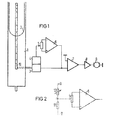
- Figure 2 shows a particularly advantageous embodiment for the device 4. This is from a hot conductor 12 arranged on the pressure transducer 3 itself, which is connected in series with a fixed resistor 11 to a fixed voltage + U, - U and at whose connection point A with the fixed resistor 11 the temperature-dependent voltage is tapped.
Landscapes
- Physics & Mathematics (AREA)
- General Physics & Mathematics (AREA)
- Measuring Fluid Pressure (AREA)
- Measuring Magnetic Variables (AREA)
Claims (2)
Priority Applications (1)
| Application Number | Priority Date | Filing Date | Title |
|---|---|---|---|
| AT79105148T ATE1122T1 (de) | 1979-04-06 | 1979-12-13 | Einrichtung zum unwirksammachen von durch temperaturschwankungen verursachten abweichungen der ausgangsspannung eines druckwandlers in magnetbandgeraeten. |
Applications Claiming Priority (2)
| Application Number | Priority Date | Filing Date | Title |
|---|---|---|---|
| DE2914037 | 1979-04-06 | ||
| DE2914037A DE2914037C2 (de) | 1979-04-06 | 1979-04-06 | Einrichtung zum Unwirksammachen von durch Temperaturschwankungen verursachten Abweichungen der Ausgangsspannung eines Druckwandlers in Magnetbandgeräten |
Publications (2)
| Publication Number | Publication Date |
|---|---|
| EP0016866A1 EP0016866A1 (fr) | 1980-10-15 |
| EP0016866B1 true EP0016866B1 (fr) | 1982-05-26 |
Family
ID=6067703
Family Applications (1)
| Application Number | Title | Priority Date | Filing Date |
|---|---|---|---|
| EP79105148A Expired EP0016866B1 (fr) | 1979-04-06 | 1979-12-13 | Dispositif pour rendre ineffectives les différences de tension de sortie d'un transformateur de pression dans des appareils à bande magnétique, causées par des fluctuations de température |
Country Status (4)
| Country | Link |
|---|---|
| US (1) | US4306689A (fr) |
| EP (1) | EP0016866B1 (fr) |
| AT (1) | ATE1122T1 (fr) |
| DE (1) | DE2914037C2 (fr) |
Cited By (1)
| Publication number | Priority date | Publication date | Assignee | Title |
|---|---|---|---|---|
| US6074629A (en) * | 1998-07-27 | 2000-06-13 | J. M. Huber Corporation | Dentifrice with a dye absorbing silica for imparting a speckled appearance thereto |
Families Citing this family (3)
| Publication number | Priority date | Publication date | Assignee | Title |
|---|---|---|---|---|
| DE3431517C2 (de) * | 1984-08-28 | 1986-09-04 | Kernforschungsanlage Jülich GmbH, 5170 Jülich | Verfahren zur Druckmessung mit einem Gasreibungsvakuummeter und Gasreibungsvakuummeter zur Durchführung des Verfahrens |
| US5228635A (en) * | 1990-01-26 | 1993-07-20 | Sony Corporation | Apparatus having a vacuum chamber for controlling a tape tension thereof/vacuum chamber apparatus for controlling tape tension |
| JP3187819B2 (ja) * | 1990-01-26 | 2001-07-16 | ソニー株式会社 | テープテンション制御装置 |
Family Cites Families (6)
| Publication number | Priority date | Publication date | Assignee | Title |
|---|---|---|---|---|
| US3354318A (en) * | 1964-04-20 | 1967-11-21 | Ampex | Loop sensing system for magnetic tape transports wherein loop intercepts light beam |
| GB1195121A (en) * | 1967-05-16 | 1970-06-17 | Int Computers Ltd | Improvements in or relating to Position Sensing Apparatus. |
| US3701494A (en) * | 1970-04-20 | 1972-10-31 | Honeywell Inc | Electropneumatically controlled servo for tape mechanism |
| US3967188A (en) * | 1973-05-24 | 1976-06-29 | Bell & Howell Company | Temperature compensation circuit for sensor of physical variables such as temperature and pressure |
| CH616743A5 (en) * | 1977-07-01 | 1980-04-15 | Bbc Brown Boveri & Cie | Device for measuring the density of gaseous media. |
| DE2840957B1 (de) * | 1978-09-20 | 1980-01-24 | Siemens Ag | Einrichtung zum Unwirksammachen von durch Temperaturschwankungen verursachten Abweichungen der Ausgangsspannung eines Druckwandlers in Magnetbandgeraeten |
-
1979
- 1979-04-06 DE DE2914037A patent/DE2914037C2/de not_active Expired
- 1979-12-13 AT AT79105148T patent/ATE1122T1/de not_active IP Right Cessation
- 1979-12-13 EP EP79105148A patent/EP0016866B1/fr not_active Expired
-
1980
- 1980-02-25 US US06/123,985 patent/US4306689A/en not_active Expired - Lifetime
Cited By (1)
| Publication number | Priority date | Publication date | Assignee | Title |
|---|---|---|---|---|
| US6074629A (en) * | 1998-07-27 | 2000-06-13 | J. M. Huber Corporation | Dentifrice with a dye absorbing silica for imparting a speckled appearance thereto |
Also Published As
| Publication number | Publication date |
|---|---|
| EP0016866A1 (fr) | 1980-10-15 |
| DE2914037C2 (de) | 1983-12-08 |
| DE2914037A1 (de) | 1980-10-16 |
| ATE1122T1 (de) | 1982-06-15 |
| US4306689A (en) | 1981-12-22 |
Similar Documents
| Publication | Publication Date | Title |
|---|---|---|
| EP0869335A2 (fr) | Dispositif et procédé pour la mesure et le controle du débit d'un fluide | |
| EP0221251A1 (fr) | Méthode pour compenser des erreurs d'un capteur à caractéristique non linéaire et dispositif pour sa mise en oeuvre | |
| DE2139999A1 (de) | Zustandsfuhlerschaltung in Brücken anordnung | |
| DE2105357A1 (de) | Gerat zum Messen des Flusses von in Leitungen stromenden Medien | |
| EP0016866B1 (fr) | Dispositif pour rendre ineffectives les différences de tension de sortie d'un transformateur de pression dans des appareils à bande magnétique, causées par des fluctuations de température | |
| EP2197117B1 (fr) | Unité de commutation destinée à produire une tension de sortie en fonction d'une valeur de données numérique et procédé de calibrage de l'unité de commutation | |
| DE2615162C2 (de) | Schaltungsanordnung zur Linearisierung der Ausgangssignale von Meßfühlern | |
| DE102007053943A1 (de) | Wärmeleitungs-Gasdruckmeßanordnung | |
| DE3202476C2 (de) | Vorrichtung zum Regeln der Temperatur in einem Ofen | |
| DE10102791A1 (de) | Elektrischer Messumformer | |
| DE2840957C2 (fr) | ||
| CH616743A5 (en) | Device for measuring the density of gaseous media. | |
| DE2203306C2 (de) | Schaltungsanordnung zur Nullpunktsverschiebung von Meßspannungen | |
| EP0249797B1 (fr) | Vanne de régulation de pression | |
| DE2163749C3 (de) | Verfahren zur Eliminierung der Temperatureinflüsse einer Schaltungsanordnung mit nicht linearer Kennliniencharakteristik | |
| DE2451281C3 (de) | Meßverstärker | |
| DE3024328A1 (de) | Einrichtung zur messung einer physikalischen groesse | |
| DE1007510B (de) | Kompensations-Vorrichtung zum Messen oder Aufzeichnen einer physikalischen Groesse | |
| DE2453704C2 (de) | Schaltungsanordnung eines Signalverstärkers für ein mittels einer Meßbrücke erzeugtes Signal | |
| EP1378063A2 (fr) | Procede et circuit permettant la linearisation de courbes caracteristiques non lineaires | |
| DE1551038C (de) | Einrichtung zur Regelung einer Dampf kraftanlage in Blockschaltung einer Konden sationsdampfturbine | |
| DE1573718C (de) | Prüfmaschine mit nach einem vorgege benen Sollwert erfolgender Regelung der Prufkraft | |
| DE19635162A1 (de) | Meßvorrichtung | |
| DE1934252C3 (de) | Schaltungsanordnung zum Betrieb mehrerer Regelkreise im Gleichlauf | |
| DE1951942A1 (de) | Messgroessenumformer,insbesondere fuer kapazitiv wirksame Geber |
Legal Events
| Date | Code | Title | Description |
|---|---|---|---|
| PUAI | Public reference made under article 153(3) epc to a published international application that has entered the european phase |
Free format text: ORIGINAL CODE: 0009012 |
|
| AK | Designated contracting states |
Designated state(s): AT BE CH FR GB IT NL |
|
| 17P | Request for examination filed |
Effective date: 19801029 |
|
| ITF | It: translation for a ep patent filed |
Owner name: STUDIO JAUMANN |
|
| GRAA | (expected) grant |
Free format text: ORIGINAL CODE: 0009210 |
|
| AK | Designated contracting states |
Designated state(s): AT BE CH FR GB IT NL |
|
| REF | Corresponds to: |
Ref document number: 1122 Country of ref document: AT Date of ref document: 19820615 Kind code of ref document: T |
|
| PGFP | Annual fee paid to national office [announced via postgrant information from national office to epo] |
Ref country code: CH Payment date: 19830228 Year of fee payment: 4 |
|
| PGFP | Annual fee paid to national office [announced via postgrant information from national office to epo] |
Ref country code: AT Payment date: 19831202 Year of fee payment: 5 |
|
| PGFP | Annual fee paid to national office [announced via postgrant information from national office to epo] |
Ref country code: NL Payment date: 19831220 Year of fee payment: 5 |
|
| PG25 | Lapsed in a contracting state [announced via postgrant information from national office to epo] |
Ref country code: CH Effective date: 19831231 Ref country code: BE Effective date: 19831231 |
|
| PGFP | Annual fee paid to national office [announced via postgrant information from national office to epo] |
Ref country code: BE Payment date: 19831231 Year of fee payment: 5 |
|
| REG | Reference to a national code |
Ref country code: CH Ref legal event code: PL |
|
| PG25 | Lapsed in a contracting state [announced via postgrant information from national office to epo] |
Ref country code: AT Effective date: 19841213 |
|
| PGFP | Annual fee paid to national office [announced via postgrant information from national office to epo] |
Ref country code: FR Payment date: 19841220 Year of fee payment: 6 |
|
| BERE | Be: lapsed |
Owner name: SIEMENS A.G. BERLIN UND MUNCHEN Effective date: 19841213 |
|
| PG25 | Lapsed in a contracting state [announced via postgrant information from national office to epo] |
Ref country code: NL Effective date: 19850701 |
|
| NLV4 | Nl: lapsed or anulled due to non-payment of the annual fee | ||
| GBPC | Gb: european patent ceased through non-payment of renewal fee | ||
| PG25 | Lapsed in a contracting state [announced via postgrant information from national office to epo] |
Ref country code: FR Free format text: LAPSE BECAUSE OF NON-PAYMENT OF DUE FEES Effective date: 19880831 |
|
| REG | Reference to a national code |
Ref country code: FR Ref legal event code: ST |
|
| PG25 | Lapsed in a contracting state [announced via postgrant information from national office to epo] |
Ref country code: GB Free format text: LAPSE BECAUSE OF NON-PAYMENT OF DUE FEES Effective date: 19881118 |
|
| PLBE | No opposition filed within time limit |
Free format text: ORIGINAL CODE: 0009261 |
|
| STAA | Information on the status of an ep patent application or granted ep patent |
Free format text: STATUS: NO OPPOSITION FILED WITHIN TIME LIMIT |