EP0016664A1 - Vorrichtung zum Ausrichten und Regeln des Spielraums zwischen zwei Schienenköpfen - Google Patents
Vorrichtung zum Ausrichten und Regeln des Spielraums zwischen zwei Schienenköpfen Download PDFInfo
- Publication number
- EP0016664A1 EP0016664A1 EP80400071A EP80400071A EP0016664A1 EP 0016664 A1 EP0016664 A1 EP 0016664A1 EP 80400071 A EP80400071 A EP 80400071A EP 80400071 A EP80400071 A EP 80400071A EP 0016664 A1 EP0016664 A1 EP 0016664A1
- Authority
- EP
- European Patent Office
- Prior art keywords
- frame
- rails
- rail
- presses
- press
- Prior art date
- Legal status (The legal status is an assumption and is not a legal conclusion. Google has not performed a legal analysis and makes no representation as to the accuracy of the status listed.)
- Granted
Links
Images


Classifications
-
- E—FIXED CONSTRUCTIONS
- E01—CONSTRUCTION OF ROADS, RAILWAYS, OR BRIDGES
- E01B—PERMANENT WAY; PERMANENT-WAY TOOLS; MACHINES FOR MAKING RAILWAYS OF ALL KINDS
- E01B29/00—Laying, rebuilding, or taking-up tracks; Tools or machines therefor
- E01B29/42—Undetachably joining or fastening track components in or on the track, e.g. by welding, by gluing; Pre-assembling track components by gluing; Sealing joints with filling components
- E01B29/46—Devices for holding, positioning, or urging together the rail ends
-
- Y—GENERAL TAGGING OF NEW TECHNOLOGICAL DEVELOPMENTS; GENERAL TAGGING OF CROSS-SECTIONAL TECHNOLOGIES SPANNING OVER SEVERAL SECTIONS OF THE IPC; TECHNICAL SUBJECTS COVERED BY FORMER USPC CROSS-REFERENCE ART COLLECTIONS [XRACs] AND DIGESTS
- Y10—TECHNICAL SUBJECTS COVERED BY FORMER USPC
- Y10T—TECHNICAL SUBJECTS COVERED BY FORMER US CLASSIFICATION
- Y10T29/00—Metal working
- Y10T29/53—Means to assemble or disassemble
- Y10T29/53978—Means to assemble or disassemble including means to relatively position plural work parts
Definitions
- the present invention relates to a device for adjusting the alignment and the intermediate distance of two rail ends for the connection of these two ends by splicing or by welding, which also makes it possible to deburr the weld formed, in the case where the two ends were connected by welding.
- the adjustment of the rails consists in adjusting the intermediate distance between the two ends to be connected, in aligning the internal vertical sides of the mushrooms of the rails to be connected, and in slightly bending the ends to raise them upwards, this bending being essentially intended for the connection by welding.
- Deburring consists in eliminating the weld bead at least on the top and both sides of the rail head and if possible on the whole of the rail profile.
- the adjustment operations are carried out essentially by means of an appropriate set of shims while the deburring operations are carried out either by hand or by machine o
- the device described in the aforementioned patent application comprises a rigid horizontal frame with an open structure capable of overlapping the two rails, providing around the two ends to connect an access zone delimited by the open structure of the frame; two primary presses and two second presses mounted in alignment on the frame and arranged such that the two primary presses are en- t re both side presses and that each assembly formed by a primary media and a secondary press can enclose one the two rails at Port Pressure d er; a retractable assembly interlayer distance adjusting and deburring carried by the frame and de- p cable between a rest position where it is ap- p u i on the frame and a working position where it is in the frame access area, said retractable assembly comprising a frame movable inside the frame access area in a direction parallel to that of the rails, this frame being provided with locking means able to make the frame integral with one or the other of the two rails to achieve an intermediate distance adjustment before the connection operation and being provided with a deburring tool capable of eliminating the
- the secondary presses are integral with the frame and the vertical adjustment of the rails is carried out by vertically adjustable bearing points capable of cooperating with the top of the rail head, respectively at the level of each secondary press.
- the present invention aims to avoid these drawbacks by providing another embodiment of the device of the aforementioned patent application to allow the vertical adjustment of the rails, which is characterized in that each secondary press is movable vertically relative to the built under the action of a jack and that two vertically adjustable bearing stops, capable of cooperating with the top of the rail head, are provided respectively between each of the two primary presses and the secondary press associated therewith.
- each secondary press is advantageously mounted on a support movable vertically under the action of a double-acting cylinder connected between the support and the frame.
- Each support is connected to the frame by links articulated each on the support and on the frame to ensure the maintenance of each support relative to the frame
- the frame of the device of the invention is supported at each end by a bogie having a jack permitting the displacement of the frame between a lowered operating position and a raised position for transport.
- Each bogie has two suspended axles which not only provide a suspension function but also make it possible to follow the vertical deformations of the rail during adjustment operations when the frame is in the service position.
- the invention also provides the installation of a device or two devices in parallel on a traveling gantry on two axles maniè- r e to be able to simultaneously perform the setting operations and optionally deburring on the two rails of the same way.
- Figures 3 to 6 show a side view of a device according to the invention worn on two bogies during four successive phases of an adjustment operation
- FIG. 7 is a top view of a traveling gantry equipped with a device similar to that of FIGS. 3 to 6 and provided with means for moving the device laterally from one row of rails to the other on a railway track;
- Figures 8 and 9 are respec - tively a side view and a top view of a gantry crane is equipped with two devices similar to that of Figures 3 to 6 enable to simultaneously perform operations of setting and / or deburring on the two rows of rails of a railroad track.
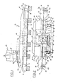
- FIG. 1 and 2 There is shown in Figures 1 and 2 a device according to the aforementioned patent application, applied to a left rail 12 and a right rail 14 placed on sleepers, which should be connected to their ends.
- the device comprises a rigid horizontal frame 10 with an open structure comprising two overlapping elements 16 and 18 fixed between them by two longitudinal beams 20 and 22.
- the overlapping element 16 is constituted by an inverted U-shaped element 24 able to overlap the rail 12 and provided with an extension 26.
- the overlapping element 18 is constituted by an inverted U-shaped element 28, capable of overlapping the rail 14 - and provided with an extension 30.
- the frame 10 of the device is placed in such a way that the middle of the latter substantially coincides with the junction of the two ends of the rails to be connected.
- the open structure of the frame which is constituted by the inside of the frame delimited by the two inverted U-shaped elements 2 4 and 28 and by the two side members 20 and 22, constitutes an access zone around the two ends of rails to be connected to allow adjustment, connection and possibly deburring operations, if the connection is made by welding.
- the overlapping element 16 is provided with a primary press 32 fixed on the inverted U-shaped element 24 and a secondary press 34 fixed on the extension 26.
- the overlapping element 18 is provided with a primary press 36 attached to the the E- ENT inverted U-28 and a secondary press 38 fixed to the extension 30, presses 36 and 38 being in alignment with the presses 32 and 34.
- the two primary presses 32 and 36 are located between the two secondary presses 34 and 38, the primary press 32, as well as the secondary press 34 being provided to grip the left rail 12, the primary press 36 and the secondary press 38 being designed to grip the right rail 14.
- the frame 10 is also provided with a retractable assembly for adjusting the intermediate distance and for deburring 40 carried by two pivoting arms 42 actuated by a double-acting cylinder 44 and movable between a rest position where it is supported on the frame 10 (see Figure 1) and a working position where it is in the access area of the frame (position shown in dotted lines in Figure 1 and position shown in Figure 2).
- the retractable assembly 40 is formed by a frame with two legs 46 and 48 connected together by two longitudinal members 50 and 52.
- the retractable assembly 40 is movable inside the access zone of the frame 10 under the action two double-acting cylinders 54 and 56, acting in a direction parallel to that of the rails, the body of which bears on the inverted U-shaped element 24 of the overlapping element 16 and the rod of which is connected to the leg 48 of the retractable assembly 40, that is to say at the leg furthest from the point of support of the jacks 54 and 56 on the frame 10.
- the legs 46 and 48 of the retractable assembly 40 are respectively provided with a tunnel 58 and a tunnel 60 allowing respectively the passage of the rail 12 and that of the rail 14.
- the passage tunnels 58 and 60 can receive corners of clamping allowing the blocking of the corresponding leg on one of the rails in order to allow an intermediate distance adjustment operation, one of the two legs being further provided with a retractable deburring tool to eliminate the welded bead formed after the connection operation, if the latter is carried out by welding.
- the primary press 32 consists of a fixed jaw 62 adjustable in the horizontal plane and able to come into abutment against one side of the rail 12 (core with mushroom) and a movable jaw 64 movable horizontally and perpendicular to the rail 12 and suitable coming to bear against the other side of the rail 12, the movable jaw 64 being subjected to the action of a single-acting cylinder 66 intended to bring it closer to the jaw 62 and to the action of two return springs 68 and 70 intended to move it away from the fixed jaw 62.
- the jack 66 can be double-acting and the springs 68 and 70 can be omitted.
- the primary press 36 comprises a fixed jaw 72 adjustable in the horizontal plane and able to bear against one side of the rail 14 (core or mushroom) and a movable jaw 74 movable horizontally and perpendicular to the rail 14 and capable of coming to bear against the other side of the rail 14, the movable jaw 74 being subjected to the action of a single-acting cylinder 76 intended to bring it closer to the fixed jaw 72 and to the action of two return springs 78 and 80 intended to move it away from the fixed jaw 72.
- the jack 76 can be double-acting and the springs 78 and 80 can be deleted.
- the secondary press 34 includes a fixed movable jaw 102 and a mobile jaw 104 movable horizontally and perpendicularly to the rail 12 under the action of a double-acting cylinder 106.
- the secondary press 38 comprises a fixed or mobile jaw 108 and a movable jaw 110 movable horizontally and perpendicular to the web of the rail 14 under the action of a double-acting cylinder 12.
- the frame 10 is further provided with two vertically adjustable support points 114 and 116 capable of cooperating respectively with the top of the head of the rail 12 and with the top of the head of the rail 14 at the level of the secondary presses 34 and 38.
- the points support 114 and 116 are adjustable respectively by means of heads 115 and 117 capable of being actuated by an appropriate key. When the primary presses and secondary presses are tightened, these support points abut on the top of the rail mushrooms and thus cooperate with the primary presses to slightly lift the ends up.
- the intermediate distance between the two butt ends to be welded is not suitable, then the intermediate distance is adjusted.
- the leg 48 of the retractable assembly 40 is then blocked on the right rail 14 by means of suitable corners and the jacks 54 and 56 are then actuated so that the frame formed by the two legs 46 and 48 and by the two side members 50 and 52 moves from left to right (direction of figure 2).
- This movement of the frame and therefore of the leg 48 causes the right rail 14 to move away from the left rail 12, which remains stationary, and consequently the increase in the intermediate distance. It then suffices to again block the presses 36 and 38, to retract the jacks 54 and 56 of the retractable assembly and to return the latter to the rest position by means of the jack 44.
- the two rails 12 and 14 being suitably adjusted and kept clamped by the presses 32, 34, 36 and 38, the connection operation of the ends is then carried out in a conventional manner, either by welding or by splicing.
- FIG 3 a device according to the invention, designated by the reference generalized r ale 210.
- This device comprises a frame 212 with an open structure defining an access zone and provided with two primary presses 214 and 216, as previously described with reference to Figures 1 and 2.
- This frame is also provided with a retractable assembly 218 for adjusting the intermediate distance and for deburring carried by an arm 220 and movable between a rest position where it is in abutment on the frame and a working position where it is located in the access area of the building.
- the retractable assembly includes all the features of the retractable assembly 40 of Figures 1 and 2.
- the frame 212 has two ends 222 and 224 desti - born supporting the frame via two respective bogies 226 and 228 These two bogies each have two suspended axles and a column 230 or 232 allowing both the pivoting of each end of the frame on its corresponding bogie as well as the height adjustment of the frame relative to the bogies.
- double-acting cylinders 234 and 236 are provided respectively on the bogies 226 and 228 to allow the height of the frame to be modified relative to the bogies.
- one of the bogies is provided with a motor (not shown) to allow the autonomous movement of the device on the railway.
- the frame is provided with two supports 238 and 240 each provided with an end press 242 or 244.
- the support 238 is connected to the frame 212 by connecting rods 246 and by a double-acting vertical cylinder 248.
- the support 240 is connected to the frame 212 by rods 250 and by a vertical cylinder 252 with double effect.
- the frame In the position shown in Figure 3, the frame is in a high position, or transport position, allowing the free movement of the device on a left rail 254 and a right rail 256 previously unclamped from their sleepers, which should be connect the respective ends 258 and 260.
- a temporary splice 262 has been installed between the ends 258 and 260 to allow the passage of the device.
- the device is in a position such that the middle of the frame is in the connection area of the two end of rails.
- the frame 212 is further provided with two support stops 2 64 and 266, adjustable vertically, able to cooperate respectively with the top of the rail head 254 and the rail head 256 between, on the one hand, the primary press 214 and the secondary press 242 and, on the other hand, the primary press 216 and the secondary press 244.
- These stops comprise a simple screw system for ensuring their adjustment in the vertical position; this setting will generally be preset for a type of rail and may be modified in the event of a change in the type of rail.
- the temporary splint 262 is removed and the jacks 234 and 236 are actuated so as to lower the frame 212 and cause the stops 264 and 266 to come into contact with the rails 254 and 256.
- the end piece 258 is raised relative to the end piece 260 so that the stop 264 first comes to press on the top of the head of the rail 254 while gradually causing the flexing of the rail 254 (FIG. 4) and that the stop 266 then comes to press on the underside of the head of the rail 256 (FIG. 5).
- the device is in the low position, the suspensions of the bogies 226 and 228 being relaxed and the weight of the device being transferred to the stops 264 and 266 to cause the two rails to bend.
- the jacks 248 and 252 are actuated to bring the secondary presses 242 and 244 into a suitable position and these presses are blocked on the sides of the rails 254 and 256.
- the ends can be raised or lowered independently. 258 and 160 with a "beam effect" in the - (. cf. Fig 6) termultipleaire stops 264 and 266.
- the intermediate distance is adjusted by means of the assembly 218 as was said with reference to the device in FIGS. 1 and 2.
- the presses are then actuated primary 214 and 216 so as to maintain the rails in the connection position, the secondary presses being always maintained and this connection is made by splicing or welding and in addition a deburring operation is carried out in the latter case.
- the primary presses are loosened 214 and 216 and the secondary presses 242 and 244 and then the device is brought to the high position, or transport position.
- the supports 238 and 240 are also reassembled by acting on the jacks 248 e-252. The device can then be moved to another connection area.
- the two bogies also include means making it possible to move the frame laterally in order to allow the connection to be made both to the right and to the left of the track, these means being for example produced as described below with reference to FIG. 7.
- FIG. 7 shows a rolling gantry comprising two platforms 268 and 270 held fixedly between them and each comprising a single axle (not shown) to allow the gantry to move on the two rows of rails 272 and 274 of a railroad track.
- the platforms 268 and 270 are each provided respectively with slides 276 and 278 arranged horizontally and transversely with respect to the direction of the rails.
- the two slides each slide to accommodate a carriage 280 and 282 serving to support a device 210 according to the invention, similar to that of FIGS. 3 to 6, by means of two columns 284 and 286 respectively, allowing the height adjustment of the device 210. in relation to the gantry crane.
- the carriages 280 and 282 are movable by appropriate means (jacks, chain transmissions, etc.) to allow the device 210 to be placed at will either above the line of rails 272, or above the line of rails 274. The device is then used as described above with reference to FIGS. 2 to 6.
- FIGS. 8 and 9 show a rolling gantry 288, identical to that of FIG. 7, comprising two platforms 290 and 292 fixedly held together and each comprising a single axle 294 and 296 to allow the gantry to move on the two rows of rails 298 and 299 of a railroad track.
- the platform 292 is also provided with two horizontal slides 304 and 306 arranged parallel and above rails 298 and 299.
- the slides 300 and 304 slide to receive respective carriages 308 and 310 which support a device 210, similar to that of FIGS. 3 to 6, by means of two columns 312 and 314 respectively, allowing the height adjustment of the device 210 relative to at the gantry.
- the runners 302 and 306 slide to receive respective carriages 316 and 318 which support a device 210 ', identical to the device 210, by means of two columns respectively 312 and 314 allowing the height adjustment of the device 210' relative to the chassis.
- FIG. 8 shows a chain transmission 324 making it possible to move the carriage 316 on its slide 302.
- the device of Figures 3 to 6 can be derailed, that is to say moved laterally out of the way. For this, it suffices to lift the frame 212 by means of the jacks 234 and 236, to put in place rail elements perpendicular to the railway track, to fully retract the jacks 234 and 236 so that the casters integral with the frame (not shown ) come to bear on the rail elements and that the two bogies 226 and 228 are lifted above the railroad tracks.
- the device of the invention can be used in the context of laying or repairing railways.
Priority Applications (1)
| Application Number | Priority Date | Filing Date | Title |
|---|---|---|---|
| AT80400071T ATE2280T1 (de) | 1979-01-24 | 1980-01-17 | Vorrichtung zum ausrichten und regeln des spielraums zwischen zwei schienenkoepfen. |
Applications Claiming Priority (2)
| Application Number | Priority Date | Filing Date | Title |
|---|---|---|---|
| FR7901798 | 1979-01-24 | ||
| FR7901798A FR2447421A2 (fr) | 1979-01-24 | 1979-01-24 | Dispositif de reglage de l'alignement et de la distance intercalaire de deux abouts de rails |
Publications (2)
| Publication Number | Publication Date |
|---|---|
| EP0016664A1 true EP0016664A1 (de) | 1980-10-01 |
| EP0016664B1 EP0016664B1 (de) | 1983-01-19 |
Family
ID=9221159
Family Applications (1)
| Application Number | Title | Priority Date | Filing Date |
|---|---|---|---|
| EP80400071A Expired EP0016664B1 (de) | 1979-01-24 | 1980-01-17 | Vorrichtung zum Ausrichten und Regeln des Spielraums zwischen zwei Schienenköpfen |
Country Status (10)
| Country | Link |
|---|---|
| US (1) | US4313382A (de) |
| EP (1) | EP0016664B1 (de) |
| JP (1) | JPS55101602A (de) |
| AT (1) | ATE2280T1 (de) |
| AU (1) | AU526780B2 (de) |
| BR (1) | BR8000432A (de) |
| CA (1) | CA1139154A (de) |
| DE (1) | DE3061650D1 (de) |
| FR (1) | FR2447421A2 (de) |
| OA (1) | OA06444A (de) |
Cited By (2)
| Publication number | Priority date | Publication date | Assignee | Title |
|---|---|---|---|---|
| EP0045688A1 (de) * | 1980-07-30 | 1982-02-10 | C. Delachaux | Einrichtung zum Richten von zwei durch Schweissen zu verbindenden Schienenenden |
| US5136140A (en) * | 1990-05-02 | 1992-08-04 | Franz Plasser Bahnbaumaschinen-Industriegesellschaft M.B.H. | Rail tensioning apparatus |
Families Citing this family (13)
| Publication number | Priority date | Publication date | Assignee | Title |
|---|---|---|---|---|
| CH654363A5 (fr) * | 1983-07-05 | 1986-02-14 | Rail Wel Inc | Machine pour le positionnement correct et la soudure bout a bout de deux extremites de rails. |
| US4753424A (en) * | 1986-03-05 | 1988-06-28 | Nippon Kokan Kabushiki Kaisha | Method of clamping rails for pressure welding the same and clamping apparatus therefor |
| IT1232099B (it) * | 1989-05-23 | 1992-01-23 | Valditerra S P A | Procedimento per la saldatura continua di tronchi di rotaia, e rotabile attrezzato per la sua attuazione |
| WO1999031322A1 (en) | 1997-12-16 | 1999-06-24 | Thelen Richard L | Rail welding apparatus incorporating rail restraining device, weld containment device and weld delivery unit |
| US6163003A (en) * | 1998-06-12 | 2000-12-19 | Chemetron-Railway Products, Inc. | Method and apparatus for controlling forging force during flash butt welding of railway rails |
| US6637727B1 (en) | 2002-04-22 | 2003-10-28 | Templeton, Kenly & Co. | Rail puller including a clamping beam and two clamping members and a method thereof |
| US20050067381A1 (en) * | 2003-01-27 | 2005-03-31 | Coomer Daniel J. | On-site rail welding apparatus |
| AT501272B8 (de) * | 2005-03-30 | 2007-02-15 | Plasser Bahnbaumasch Franz | Verfahren zum entfernen schadhafter schienenstücke eines gleises und maschine |
| CN101971695A (zh) * | 2008-03-12 | 2011-02-09 | 切梅特朗-铁路产品公司 | 轨道现场铁轨焊接系统 |
| AU2009344628B2 (en) * | 2009-04-16 | 2014-06-12 | Davide Vaia | Welding head for rail welding |
| EP2483979B1 (de) * | 2009-09-30 | 2017-04-05 | Orange | Vorrichtung zur verlegung eines signalkabels |
| US8844915B2 (en) * | 2012-02-29 | 2014-09-30 | Superior Industrial Services | Fixture and method of welding locomotive sills |
| US20150345544A1 (en) * | 2015-08-14 | 2015-12-03 | Caterpillar Inc. | System and method of insertion for shim |
Citations (3)
| Publication number | Priority date | Publication date | Assignee | Title |
|---|---|---|---|---|
| DE1271740B (de) * | 1966-01-05 | 1968-07-04 | Elektro Thermit Gmbh | Vorrichtung zur Durchfuehrung von aluminothermischen Schienenverbindungsschweissungen |
| FR2141406A1 (de) * | 1971-06-01 | 1973-01-26 | Sncf | |
| US3726232A (en) * | 1970-07-16 | 1973-04-10 | Trakwork Equipment Co | Track welding system |
Family Cites Families (6)
| Publication number | Priority date | Publication date | Assignee | Title |
|---|---|---|---|---|
| GB1478852A (en) * | 1974-08-20 | 1977-07-06 | Greenside Hydraulics Ltd | Rail tensioning devices |
| US3982091A (en) * | 1974-10-15 | 1976-09-21 | H. A. Schlatter Ag | Welding apparatus |
| AU517045B2 (en) * | 1977-07-08 | 1981-07-02 | C. Delachaux SA | Aligning and setting gap between rails |
| CH621502A5 (de) * | 1977-09-09 | 1981-02-13 | Schlatter Ag | |
| AT357595B (de) * | 1977-12-28 | 1980-07-25 | Plasser Bahnbaumasch Franz | Fahrbare schienenschweissmaschine |
| CH632948A5 (de) * | 1978-11-10 | 1982-11-15 | Schlatter Ag | Einrichtung zum stirnseitigen aneinanderschweissen zweier profilstangen. |
-
1979
- 1979-01-24 FR FR7901798A patent/FR2447421A2/fr active Granted
-
1980
- 1980-01-17 DE DE8080400071T patent/DE3061650D1/de not_active Expired
- 1980-01-17 EP EP80400071A patent/EP0016664B1/de not_active Expired
- 1980-01-17 AT AT80400071T patent/ATE2280T1/de not_active IP Right Cessation
- 1980-01-21 US US06/113,791 patent/US4313382A/en not_active Expired - Lifetime
- 1980-01-22 AU AU54806/80A patent/AU526780B2/en not_active Ceased
- 1980-01-23 CA CA000344255A patent/CA1139154A/fr not_active Expired
- 1980-01-23 BR BR8000432A patent/BR8000432A/pt unknown
- 1980-01-24 OA OA57004A patent/OA06444A/xx unknown
- 1980-01-24 JP JP771180A patent/JPS55101602A/ja active Granted
Patent Citations (3)
| Publication number | Priority date | Publication date | Assignee | Title |
|---|---|---|---|---|
| DE1271740B (de) * | 1966-01-05 | 1968-07-04 | Elektro Thermit Gmbh | Vorrichtung zur Durchfuehrung von aluminothermischen Schienenverbindungsschweissungen |
| US3726232A (en) * | 1970-07-16 | 1973-04-10 | Trakwork Equipment Co | Track welding system |
| FR2141406A1 (de) * | 1971-06-01 | 1973-01-26 | Sncf |
Cited By (2)
| Publication number | Priority date | Publication date | Assignee | Title |
|---|---|---|---|---|
| EP0045688A1 (de) * | 1980-07-30 | 1982-02-10 | C. Delachaux | Einrichtung zum Richten von zwei durch Schweissen zu verbindenden Schienenenden |
| US5136140A (en) * | 1990-05-02 | 1992-08-04 | Franz Plasser Bahnbaumaschinen-Industriegesellschaft M.B.H. | Rail tensioning apparatus |
Also Published As
| Publication number | Publication date |
|---|---|
| FR2447421B2 (de) | 1982-06-11 |
| DE3061650D1 (en) | 1983-02-24 |
| OA06444A (fr) | 1981-07-31 |
| AU526780B2 (en) | 1983-01-27 |
| CA1139154A (fr) | 1983-01-11 |
| ATE2280T1 (de) | 1983-02-15 |
| JPS55101602A (en) | 1980-08-02 |
| EP0016664B1 (de) | 1983-01-19 |
| FR2447421A2 (fr) | 1980-08-22 |
| BR8000432A (pt) | 1980-10-07 |
| US4313382A (en) | 1982-02-02 |
| JPS6128041B2 (de) | 1986-06-28 |
| AU5480680A (en) | 1980-07-31 |
Similar Documents
| Publication | Publication Date | Title |
|---|---|---|
| EP0016664B1 (de) | Vorrichtung zum Ausrichten und Regeln des Spielraums zwischen zwei Schienenköpfen | |
| EP0019984B1 (de) | Zug zum Erneuern eines Eisenbahngleises | |
| EP0355240B1 (de) | Zug zur Erneuerung eines Eisenbahngleises | |
| CA1119887A (fr) | Dispositif de reglage de l'alignement et de la distance intercalaire de deux abouts de rails | |
| CA1140600A (fr) | Dispositif de reglage de deux abouts de rails a raccorder par soudure | |
| EP0045688B1 (de) | Einrichtung zum Richten von zwei durch Schweissen zu verbindenden Schienenenden | |
| EP0132227B1 (de) | Vorrichtung zum einwandfreien Ausrichten und Schienenstossschweissen von zwei Schienenenden | |
| EP0501183B1 (de) | Vorrichtung zur Wiederprofilierung von Eisenbahnschienen | |
| WO2018069615A1 (fr) | Système de transport, de chargement et de déchargement de rails d'une voie ferroviaire | |
| EP0564555B1 (de) | Vorrichtung um seitliches umladen von containern zu gewährleisten | |
| EP0358697B1 (de) | Lenk- und tragevorrichtung für ein eisenbahnfahrzeug | |
| FR2667628A1 (fr) | Machine roulante de traitement de voie ferree, en particulier machine de bourrage, de levage et de dressage de voie ferree pour la zone d'aiguillage et de croisement. | |
| EP0446130A1 (de) | Anlage zum Richten | |
| EP0505240B1 (de) | Vorrichtung zum Ver- und Ersetzen von Eisenbahnelementen und Verfahren zur Verwendung dieser Vorrichtung | |
| FR2615898A1 (fr) | Machine cribleuse de lit de ballast de voie ferree a chaine transporteuse ou degarnisseuse sans fin | |
| FR2572432A1 (fr) | Chariot sur rails pour le remplacement ou la pose et la depose ainsi que pour le transport de travees de voie ferree. | |
| EP0332489B1 (de) | Stellvorrichtung für ein Eisenbahnfahrzeug auf einer Raddrehbank | |
| FR2547514A1 (fr) | Systeme de remplacement de cages de laminoirs a profiles, chariot porte-cages multifonctions pour la mise en place sur les sites de laminage et le transport vers les sites de premontage | |
| CH653072A5 (fr) | Machine ferroviaire pour la pose et la depose de troncons ou d'appareils de voie montes. | |
| EP3326885B1 (de) | Keil zum wiedereingleisen eines auf schienen geführten fahrzeugs, und entsprechendes verfahren zur wiedereingleisung | |
| FR2668441A1 (fr) | Dispositif anti-derive d'un vehicule ferroviaire circulant sur une voie ferree. | |
| EP0364348B1 (de) | Vorrichtung, verschiebbar auf zwei einander kreuzenden, durch einen Höhenunterschied getrennten Rollenbahnen, wie eine Eisenbahn und ein Rangiergleis auf einem Bahnsteig | |
| FR2465030A1 (fr) | Machine de positionnement de traverses sur le ballast d'une voie ferree | |
| EP0332040A1 (de) | Eisenbahnwagen zum Transport von Platten auf Böcken | |
| FR2562573A1 (fr) | Dispositif de levage de voie ferree |
Legal Events
| Date | Code | Title | Description |
|---|---|---|---|
| PUAI | Public reference made under article 153(3) epc to a published international application that has entered the european phase |
Free format text: ORIGINAL CODE: 0009012 |
|
| AK | Designated contracting states |
Designated state(s): AT BE CH DE GB IT NL SE |
|
| 17P | Request for examination filed |
Effective date: 19810427 |
|
| R17P | Request for examination filed (corrected) |
Effective date: 19810306 |
|
| ITF | It: translation for a ep patent filed |
Owner name: UFFICIO TECNICO ING. A. MANNUCCI |
|
| GRAA | (expected) grant |
Free format text: ORIGINAL CODE: 0009210 |
|
| AK | Designated contracting states |
Designated state(s): AT BE CH DE GB IT NL SE |
|
| REF | Corresponds to: |
Ref document number: 2280 Country of ref document: AT Date of ref document: 19830215 Kind code of ref document: T |
|
| REF | Corresponds to: |
Ref document number: 3061650 Country of ref document: DE Date of ref document: 19830224 |
|
| PGFP | Annual fee paid to national office [announced via postgrant information from national office to epo] |
Ref country code: AT Payment date: 19900123 Year of fee payment: 11 |
|
| PGFP | Annual fee paid to national office [announced via postgrant information from national office to epo] |
Ref country code: SE Payment date: 19900125 Year of fee payment: 11 |
|
| PGFP | Annual fee paid to national office [announced via postgrant information from national office to epo] |
Ref country code: NL Payment date: 19900131 Year of fee payment: 11 |
|
| PGFP | Annual fee paid to national office [announced via postgrant information from national office to epo] |
Ref country code: BE Payment date: 19900213 Year of fee payment: 11 |
|
| PG25 | Lapsed in a contracting state [announced via postgrant information from national office to epo] |
Ref country code: AT Effective date: 19910117 |
|
| PG25 | Lapsed in a contracting state [announced via postgrant information from national office to epo] |
Ref country code: SE Effective date: 19910118 |
|
| PG25 | Lapsed in a contracting state [announced via postgrant information from national office to epo] |
Ref country code: BE Effective date: 19910131 |
|
| PG25 | Lapsed in a contracting state [announced via postgrant information from national office to epo] |
Ref country code: NL Effective date: 19910801 |
|
| NLV4 | Nl: lapsed or anulled due to non-payment of the annual fee | ||
| PGFP | Annual fee paid to national office [announced via postgrant information from national office to epo] |
Ref country code: DE Payment date: 19920129 Year of fee payment: 13 |
|
| ITTA | It: last paid annual fee | ||
| PGFP | Annual fee paid to national office [announced via postgrant information from national office to epo] |
Ref country code: GB Payment date: 19920203 Year of fee payment: 13 Ref country code: CH Payment date: 19920203 Year of fee payment: 13 |
|
| PG25 | Lapsed in a contracting state [announced via postgrant information from national office to epo] |
Ref country code: GB Effective date: 19930117 |
|
| PG25 | Lapsed in a contracting state [announced via postgrant information from national office to epo] |
Ref country code: CH Effective date: 19930131 |
|
| GBPC | Gb: european patent ceased through non-payment of renewal fee |
Effective date: 19930117 |
|
| REG | Reference to a national code |
Ref country code: CH Ref legal event code: PL |
|
| PG25 | Lapsed in a contracting state [announced via postgrant information from national office to epo] |
Ref country code: DE Effective date: 19931001 |
|
| EUG | Se: european patent has lapsed |
Ref document number: 80400071.9 Effective date: 19910910 |
|
| PLBE | No opposition filed within time limit |
Free format text: ORIGINAL CODE: 0009261 |
|
| STAA | Information on the status of an ep patent application or granted ep patent |
Free format text: STATUS: NO OPPOSITION FILED WITHIN TIME LIMIT |