EP0016664A1 - Apparatus for aligning and setting the gap between two rail-ends - Google Patents
Apparatus for aligning and setting the gap between two rail-ends Download PDFInfo
- Publication number
- EP0016664A1 EP0016664A1 EP80400071A EP80400071A EP0016664A1 EP 0016664 A1 EP0016664 A1 EP 0016664A1 EP 80400071 A EP80400071 A EP 80400071A EP 80400071 A EP80400071 A EP 80400071A EP 0016664 A1 EP0016664 A1 EP 0016664A1
- Authority
- EP
- European Patent Office
- Prior art keywords
- frame
- rails
- rail
- presses
- press
- Prior art date
- Legal status (The legal status is an assumption and is not a legal conclusion. Google has not performed a legal analysis and makes no representation as to the accuracy of the status listed.)
- Granted
Links
Images


Classifications
-
- E—FIXED CONSTRUCTIONS
- E01—CONSTRUCTION OF ROADS, RAILWAYS, OR BRIDGES
- E01B—PERMANENT WAY; PERMANENT-WAY TOOLS; MACHINES FOR MAKING RAILWAYS OF ALL KINDS
- E01B29/00—Laying, rebuilding, or taking-up tracks; Tools or machines therefor
- E01B29/42—Undetachably joining or fastening track components in or on the track, e.g. by welding, by gluing; Pre-assembling track components by gluing; Sealing joints with filling components
- E01B29/46—Devices for holding, positioning, or urging together the rail ends
-
- Y—GENERAL TAGGING OF NEW TECHNOLOGICAL DEVELOPMENTS; GENERAL TAGGING OF CROSS-SECTIONAL TECHNOLOGIES SPANNING OVER SEVERAL SECTIONS OF THE IPC; TECHNICAL SUBJECTS COVERED BY FORMER USPC CROSS-REFERENCE ART COLLECTIONS [XRACs] AND DIGESTS
- Y10—TECHNICAL SUBJECTS COVERED BY FORMER USPC
- Y10T—TECHNICAL SUBJECTS COVERED BY FORMER US CLASSIFICATION
- Y10T29/00—Metal working
- Y10T29/53—Means to assemble or disassemble
- Y10T29/53978—Means to assemble or disassemble including means to relatively position plural work parts
Landscapes
- Engineering & Computer Science (AREA)
- Architecture (AREA)
- Civil Engineering (AREA)
- Structural Engineering (AREA)
- Escalators And Moving Walkways (AREA)
- Butt Welding And Welding Of Specific Article (AREA)
- Machines For Laying And Maintaining Railways (AREA)
- Electrical Discharge Machining, Electrochemical Machining, And Combined Machining (AREA)
- Control Of Vehicles With Linear Motors And Vehicles That Are Magnetically Levitated (AREA)
- Leg Units, Guards, And Driving Tracks Of Cranes (AREA)
- Paper (AREA)
- Vehicle Body Suspensions (AREA)
- Body Structure For Vehicles (AREA)
- Mounting, Exchange, And Manufacturing Of Dies (AREA)
- Railway Tracks (AREA)
Abstract
Chaque presse secondaire (242, 244) est déplaçable verticalement par rapport au bâti sous l'action d'un vérin (248, 252) et que deux butées d'appui (264, 266) réglables verticalement, aptes à coopérer avec le dessus du champignon du rail, sont prévues respectivement entre chacune des deux presses primaires (214, 216) et la presse secondaire (242, 244) qui lui est associée.Each secondary press (242, 244) is vertically movable relative to the frame under the action of a jack (248, 252) and that two support stops (264, 266) adjustable vertically, able to cooperate with the top of the rail head, are provided respectively between each of the two primary presses (214, 216) and the secondary press (242, 244) associated therewith.
Description
La présente invention concerne un dispositif de réglage de l'alignement et de la distance intercalaire de deux abouts de rails pour le raccordement de ces deux abouts par éclissage ou par soudure, qui permet également de réaliser l'ébavurage de la soudure formée, dans le cas ou le raccordement des deux abouts a été réalisé par soudure.The present invention relates to a device for adjusting the alignment and the intermediate distance of two rail ends for the connection of these two ends by splicing or by welding, which also makes it possible to deburr the weld formed, in the case where the two ends were connected by welding.
Dans les opérations de raccordement de deux abouts de rails, en particulier de rails de chemin de fer, il faut procéder avant leur raccordement à un réglage des rails. En outre, lorsque le raccordement est réalisé par soudure, par exemple par soudure aluminothermique, il faut procéder après soudure à un ébavurage au moins partiel et si possible total du bourrelet de soudure formé.In the operations of connecting two ends of rails, in particular railway rails, an adjustment of the rails must be carried out before their connection. In addition, when the connection is made by welding, for example by thermite welding, it is necessary to carry out after welding a deburring at least partial and if possible total of the welded bead formed.
Le réglage des rails consiste à régler la distance intercalaire entre les deux abouts à raccorder, à aligner les côtés verticaux intérieurs des champignons des rails à raccorder, et à cintrer légèrement les abouts pour les relever vers le haut, ce cintrage étant essentiellement destiné au raccordement par soudure.The adjustment of the rails consists in adjusting the intermediate distance between the two ends to be connected, in aligning the internal vertical sides of the mushrooms of the rails to be connected, and in slightly bending the ends to raise them upwards, this bending being essentially intended for the connection by welding.
L'ébavurage consiste à éliminer le bourrelet de soudure au moins sur le dessus et les deux côtés du champignon du rail et si possible sur la totalité du profil du rail.Deburring consists in eliminating the weld bead at least on the top and both sides of the rail head and if possible on the whole of the rail profile.
Les opérations de réglage se font essentiellement au moyen de jeu de cales approprié alors que les opérations d'ébavurage se font soit à la main, soit à la machineo The adjustment operations are carried out essentially by means of an appropriate set of shims while the deburring operations are carried out either by hand or by machine o
Etant donné que presque toutes ces opérations se font à la main, elles présentent de nom- breux inconvénients en ce sens qu'elles sont longues à réaliser, qu'elles ne présentent pas toujours la fiabilité souhaitable et qu'elles nécessitent une main-d'oeuvre qualifiée.Since almost all of these operations are done by hand, they present NOM b reu x drawbacks in that they are slow to realize that they do not always have the desired reliability and require a hand - qualified work.
Pour éviter ces inconvénients, la Demande- resse a proposé dans la demande de brevet français 77 21157 déposée le 8 juillet 1977 un dispositif permettant de réaliser toutes ces opérations plus rapi- dement, avec plus de fiabilité, et avec un minimum de main-d'oeuvre qualifiée.To avoid these drawbacks, the Application- ress ea proposed in the French patent application 77 21 157 filed July 8, 1977 a device all to achieve these operations more rapi- edema nt, more reliably, and with minimal hand - qualified work.
Le dispositif décrit dans la demande de brevet précitée comprend un bâti horizontal rigide à structure ouverte apte à chevaucher les deux rails en ménageant autour des deux abouts à raccorder une zone d'accès délimitée par la structure ouverte du bâti; deux presses primaires et deux presses secondaires montées alignées sur le bâti et disposées de manière telle que les deux presses primaires se trouvent en- tre les deux presses secondaires et que chaque ensemble formé par une presse primaire et une presse secondaire puisse enserrer l'un des deux rails à raccor- der; un ensemble escamotable de réglage de distance intercalaire et d'ébavurage porté par le bâti et dé- plaçable entre une position de repos où il est en ap- pui sur le bâti et une position de travail où il se trouve dans la zone d'accès du bâti, ledit ensemble escamotable comportant un cadre déplaçable à l'intérieur de la zone d'accès du bâti dans une direction parallèle à celle des rails, ce cadre étant muni de moyens de blocage aptes à rendre le cadre solidaire de l'un ou l'autre des deux rails pour réaliser un réglage de distance intercalaire avant l'opération de raccordement et étant muni d'un outil d'ébavurage apte à éliminer le bourrelet de soudure après l'opération de raccordement, dans le cas où celle-ci est réalisée par soudure.The device described in the aforementioned patent application comprises a rigid horizontal frame with an open structure capable of overlapping the two rails, providing around the two ends to connect an access zone delimited by the open structure of the frame; two primary presses and two second presses mounted in alignment on the frame and arranged such that the two primary presses are en- t re both side presses and that each assembly formed by a primary media and a secondary press can enclose one the two rails at Port Pressure d er; a retractable assembly interlayer distance adjusting and deburring carried by the frame and de- p cable between a rest position where it is ap- p u i on the frame and a working position where it is in the frame access area, said retractable assembly comprising a frame movable inside the frame access area in a direction parallel to that of the rails, this frame being provided with locking means able to make the frame integral with one or the other of the two rails to achieve an intermediate distance adjustment before the connection operation and being provided with a deburring tool capable of eliminating the weld bead after the connection operation, in the case where this is carried out by welding.
Dans le mode de réalisation décrit dans la demande de brevet précitée, les presses secondaires sont solidaires du bâti et le réglage vertical des rails est réalisé par des points d'appui réglables verticalement aptes à coopérer avec le dessus du champignon des rails, respectivement au niveau de chaque presse secondaire.In the embodiment described in the aforementioned patent application, the secondary presses are integral with the frame and the vertical adjustment of the rails is carried out by vertically adjustable bearing points capable of cooperating with the top of the rail head, respectively at the level of each secondary press.
Un tel mode de réalisation a toutefois pour inconvénient de ne pas permettre d'effectuer facilement un réglage vertical des rails en toute circonstance .However, such an embodiment has the drawback of not making it possible to easily adjust the rails vertically in all circumstances.
La présente invention vise à éviter ces inconvénients en prévoyant un autre mode de réalisation du dispositif de la demande de brevet précitée pour permettre d'effectuer le réglage vertical des rails, qui est caractérisé par le fait que chaque presse secondaire est déplaçable verticalement par rapport au bâti sous l'action d'un vérin et que deux butées d'appui réglables verticalement, aptes à coopérer avec le dessus du champignon du rail, sont prévues respectivement entre chacune des deux presses primaires et la presse secondaire qui lui est associée.The present invention aims to avoid these drawbacks by providing another embodiment of the device of the aforementioned patent application to allow the vertical adjustment of the rails, which is characterized in that each secondary press is movable vertically relative to the built under the action of a jack and that two vertically adjustable bearing stops, capable of cooperating with the top of the rail head, are provided respectively between each of the two primary presses and the secondary press associated therewith.
Selon l'invention, chaque presse secondaire est avantageusement montée sur un support déplaçable verticalement sous l'action d'un vérin à double effet relié entre le support et le bâti.According to the invention, each secondary press is advantageously mounted on a support movable vertically under the action of a double-acting cylinder connected between the support and the frame.
Chaque support est relié au bâti par des biellettes articulées chacune sur le support et sur le bâti pour assurer le maintien de chaque support par rapport au bâtiEach support is connected to the frame by links articulated each on the support and on the frame to ensure the maintenance of each support relative to the frame
Le bâti du dispositif de l'invention est supporté à chaque extrémité par un bogie comportant un vérin autorisant le déplacement du bâti entre u- ne position basse de service et une position haute de transport.The frame of the device of the invention is supported at each end by a bogie having a jack permitting the displacement of the frame between a lowered operating position and a raised position for transport.
Chaque bogie comporte deux essieux suspendus qui non seulement assurent une fonction de suspension mais permettent aussi de suivre les déformations verticales du rail lors des opérations de réglage lorsque le bâti est en position de service.Each bogie has two suspended axles which not only provide a suspension function but also make it possible to follow the vertical deformations of the rail during adjustment operations when the frame is in the service position.
L'invention prévoit également le montage d'un dispositif ou de deux dispositifs en parallèle sur un portique roulant sur deux essieux de maniè- re à pouvoir réaliser simultanément les opérations de réglage et éventuellement d'ébavurage sur les deux files de rails d'une même voie.The invention also provides the installation of a device or two devices in parallel on a traveling gantry on two axles maniè- r e to be able to simultaneously perform the setting operations and optionally deburring on the two rails of the same way.
D'autres caractéristiques et avantages de l'invention seront mieux compris à la lecture de la description qui va suivre et qui se réfère aux dessins annexés donnés uniquement à titre d'exemple et sur lesquels :
- La figure 1 est une vue en élévation de face du dispositif de la demande de brevet précitée, dans lequel l'ensemble escamotable d'ébavurage est en position de repos;
- la figure 2 est une vue de dessus du dispo- sitif de la figure 1, l'ensemble escamotable étant en position de travail pour réaliser une opération d'ébavurage;
- Figure 1 is a front elevational view of the device of the aforementioned patent application, in which the retractable deburring assembly is in the rest position;
- Figure 2 is a top view of the Avail- s itive of Figure 1, the retractable assembly is in the working position to carry out a deflashing operation;
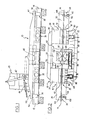
les figures 3 à 6 représentent une vue de côté d'un dispositif selon l'invention porté sur deux bogies au cours de quatre phases successives d'une opération de réglage;Figures 3 to 6 show a side view of a device according to the invention worn on two bogies during four successive phases of an adjustment operation;
la figure 7 est une vue de dessus d'un portique roulant équipé d'un dispositif analogue à celui des figures 3 à 6 et pourvu de moyens pour déplacer latéralement le dispositif d'une file de rails à l'autre sur une voie ferrée; etFIG. 7 is a top view of a traveling gantry equipped with a device similar to that of FIGS. 3 to 6 and provided with means for moving the device laterally from one row of rails to the other on a railway track; and
les figures 8 et 9 représentent respecti- vement une vue de côté et une vue de dessus d'un portique roulant équipé de deux dispositifs analogues à celui des figures 3 à 6 pour permettre de réaliser simultanément des opérations de réglage et/ou d'ébavurage sur les deux files de rails d'une voie ferrée.Figures 8 and 9 are respec - tively a side view and a top view of a gantry crane is equipped with two devices similar to that of Figures 3 to 6 enable to simultaneously perform operations of setting and / or deburring on the two rows of rails of a railroad track.
Pour faciliter la description du dispositif de l'invention, on décrira au préalable en référence aux figures 1 et 2 le dispositif connu par la demande de brevet français 77 21157 déjà citée.To facilitate the description of the device of the invention, the device known from French patent application 77 21157 already cited will be described with reference to FIGS. 1 and 2.
On a représenté sur les figures 1 et 2 un dispositif selon la demande de brevet précitée, appliqué sur un rail de gauche 12 et un rail de droite 14 posés sur traverses, dont il convient de réaliser le raccordement de leurs abouts. Le dispositif comprend un bâti horizontal rigide 10 à structure ouverte comportant deux éléments de chevauchement 16 et 18 fixés entre eux par deux longerons longitudinaux 20 et 22. L'élément de chevauchement 16 est constitué par un élément en U renversé 24 apte à chevaucher le rail 12 et muni d'un prolongement 26. De même, l'élément de chevauchement 18 est constitué par un élément en U renversé 28, apte à chevaucher le rail 14--et muni d'un prolongement 30.There is shown in Figures 1 and 2 a device according to the aforementioned patent application, applied to a
Le bâti 10 du dispositif est placé de manière telle que le milieu de celui-ci coïncide sensiblement avec la jonction des deux abouts de rails à raccorder. De cette manière, la structure ouverte du bâti, qui est constituée par l'intérieur du bâti délimité par les deux éléments en forme de U renversé 24 et 28 et par les deux longerons 20 et 22, constitue une zone d'accès autour des deux abouts de rails à raccorder pour permettre les opérations de réglage, de raccordement et éventuellement d'ébavurage, dans le cas où le raccordement est réalisé par soudure.The
L'élément de chevauchement 16 est muni d'une presse primaire 32 fixée sur l'élément en U renversé 24 et d'une presse secondaire 34 fixée sur le prolongement 26. De même, l'élément de chevauchement 18 est muni d'une presse primaire 36 fixée sur l'é- lément en U renversé 28 et d'une presse secondaire 38 fixée sur le prolongement 30, les presses 36 et 38 étant dans l'alignement des presses 32 et 34.The overlapping
Les deux presses primaires 32 et 36 se trouvent entre les deux presses secondaires 34 et 38, la presse primaire 32, ainsi que la presse secondaire 34 étant prévues pour enserrer le rail de gauche 12, la presse primaire 36 et la presse secondaire 38`étant prévues pour enserrer le rail de droite 14.The two
Le bâti 10 est en outre muni d'un ensemble escamotable de réglage de distance intercalaire et d'ébavurage 40 porté par deux bras pivotants 42 actionnés par un vérin à double effet 44 et déplaçable entre une position de repos où il est en appui sur le bâti 10 (cf. figure 1) et une position de travail où il se trouve dans la zone d'accès du bâti (position représentée en traits pointillés sur la figure 1 et position représentée sur la figure 2).The
L'ensemble escamotable 40 est formé par un cadre à deux jambages 46 et 48 reliés entre eux par deux longerons 50 et 52. L'ensemble escamotable 40 est déplaçable à l'intérieur de la zone d'accès du bâti 10 sous l'action de deux vérins à double effet 54 et 56, agissant dans une direction parallèle à celle des rails, dont le corps prend appui sur l'élément en U renversé 24 de l'élément de chevauchement 16 et dont la tige est reliée au jambage 48 de l'ensemble escamotable 40, c'est-à-dire au jambage le plus éloigné du point d'appui des vérins 54 et 56 sur le bâti 10.The
Les jambages 46 et 48 de l'ensemble escamotable 40 sont pourvus respectivement d'un tunnel 58 et d'un tunnel 60 permettant respectivement le passage du rail 12 et celui du rail 14. Les tunnels de passage 58 et 60 peuvent recevoir des coins de serrage permettant le blocage du jambage correspondant sur l'un des rails en vue de permettre une opération de réglage de distance intercalaire, l'un des deux jambages étant en outre pourvu d'un outil d'ébavurage escamotable pour éliminer le bourrelet de soudure formé après l'opération de raccordement, dans le cas où cette dernière est réalisée par soudure.The
La presse primaire 32 se compose d'une mâchoire fixe 62 réglable dans le plan horizontal et apte à venir en appui contre un côté du rail 12 (âme eu champignon) et d'une mâchoire mobile 64 déplaçable horizontalement et perpendiculairement au rail 12 et apte à venir en appui contre l'autre côté du rail 12, la mâchoire mobile 64 étant soumise à l'action d'un vérin à simple effet 66 destiné à la rapprocher de la mâchoire 62 et à l'action de deux ressorts de rappel 68 et 70 destinés à l'éloigner de la mâchoire fixe 62. En variante, le vérin 66 peut être à double effet et les ressorts 68 et 70 peuvent être supprimés.The
De même, la presse primaire 36 comporte une mâchoire fixe 72 réglable dans le plan horizontal et apte à venir en appui contre un côté du rail 14 (âme ou champignon) et une mâchoire mobile 74 déplaçable horizontalement et perpendiculairement au rail 14 et apte à venir en appui contre l'autre côté du rail 14, la mâchoire mobile 74 étant soumise à l'action d'un vérin à simple effet 76 destiné à la rapprocher de la mâchoire fixe 72 et à l'action de deux ressorts de rappel 78 et 80 destinés à l'éloigner de la mâchoire fixe 72. En variante, le vérin 76 peut être à double effet et les ressorts 78 et 80 peuvent être supprimés.Likewise, the
La presse secondaire 34 comporte une mâchoirefixe eu mobile 102 et une mâchoire mobile 104 déplaçable horizontalement et perpendiculairement au rail 12 sous l'action d'un vérin à double effet 106. De même, la presse secondaire 38 comporte une mâchoire fixe ou mobile 108et une mâchoire mobile 110 déplaçable horizontalement et perpendiculairement à l'âme du rail 14 sous l'action d'un vérin à double effet 12.The
Le bâti 10 est en outre muni de deux points d'appui réglables verticalement 114 et 116 aptes à coopérer respectivement avec le dessus du champignon du rail 12 et avec le dessus du champignon du rail 14 au niveau des presses secondaires 34 et 38. Les points d'appui 114 et 116 sont réglables respectivement au moyen de têtes 115 et 117 susceptibles d'être actionnées par une clé appropriée. Lors du serrage des presses primaires et des presses secondaires, ces points d'appui viennent en butée sur le dessus des champignons des rails et coopèrent ainsi avec les presses primaires pour réaliser un léger relevage des abouts vers le haut.The
Dans le cas où la distance intercalaire entre les deux abouts à souder n'est pas convenable, on effectue alors le réglage de cette distance intercalaire.In the event that the intermediate distance between the two butt ends to be welded is not suitable, then the intermediate distance is adjusted.
Pour cela, on abaisse l'ensemble escamota- blé 40 au muyen du vérin 44 pour l'amener en position de travail.For this, we lower the
S'il s'agit d'augmenter la distance intercalaire, on desserre uniquement la presse primaire 36 et la presse secondaire 38 qui enserraient le rail de droite 14, le rail de gauche 12 restant enserré au moyen de la presse primaire 32 et de la presse secondaire 34.If it is a question of increasing the intermediate distance, only the
On bloque alors le jambage 48 de l'ensemble escamotable 40 sur le rail de droite 14 au moyen de coins appropriés et on actionne ensuite les vérins 54 et 56 de manière que le cadre formé par les deux jambages 46 et 48 et par les deux longerons 50 et 52 se déplace de la gauche vers la droite (sens de la figure 2). Ce déplacement du cadre et par conséquent du jambage 48 provoque l'éloignement du rail de droite 14 par rapport au rail de gauche 12, qui reste immobile, et par suite l'augmentation de la distance intercalaire. Il suffit alors de bloquer à nouveau les presses 36 et 38, de rétracter les vérins 54 et 56 de l'ensemble escamotable et de ramener ce dernier en position de repos au moyen du vérin 44.The
S'il s'agit de diminuer la distance intercalaire, on desserre uniquement la presse primaire 32 et la presse secondaire 34 qui enserraient le rail de gauche 12, le rail de droite 14 restant enserré au moyen de la presse primaire 36 et de la presse secondaire 38. On bloque alors le jambage 46 de l'ensemble escamotable 40 sur le rail de gauche 12 au moyen des coins précités et on actionne ensuite les vérins 54 et 56 pour provoquer le déplacement du cadre et par conséquent du jambage 46 de la gauche vers la droite (sens de la figure 2). Ce déplacement provoque le rapprochement du rail de gauche 12 par rapport au rail de droite 14, qui reste immobile, et par suite la diminution de la distance intercalaire. Il suffit alors de bloquer à nouveau les presses 32 et 34, de rétracter les vérins 54 et 56 de l'ensemble escamotable et de ramener ce dernier en position de repos au moyen du vérin 44.If it is a question of reducing the intermediate distance, only the
Les deux rails 12 et 14 étant convenablement réglés et maintenus enserrés par les presses 32, 34, 36 et 38, on procède alors de façon classique à l'opération de raccordement des abouts, soit par soudure, soit par éclissage.The two
On décrira maintenant le dispositif de l'invention en référence particulière aux figures 3 à 6,The device of the invention will now be described with particular reference to FIGS. 3 to 6,
On a représenté sur la figure 3 un dispositif selon l'invention, désigné par la référence géné- rale 210. Ce dispositif comprend un bâti 212 à structure ouverte délimitant une zone d'accès et muni de deux presses primaires 214 et 216, comme décrit précédemment en référence aux figures 1 et 2.There is shown in Figure 3 a device according to the invention, designated by the reference generalized r
Ce bâti est également pourvu d'un ensemble escamotable 218 de réglage de distance intercalaire et d'ébavurage porté par un bras 220 et déplaçable entre une position de repos où il est en appui sur le bâti et une position de travail où il se trouve dans la zone d'accès du bâti. Cet ensemble escamotable reprend l'ensemble des caractéristiques de l'ensemble escamotable 40 des figures 1 et 2. Le bâti 212 est pourvu de deux extrémités 222 et 224 desti- nées à supporter le bâti par l'intermédiaire de deux bogies respectifs 226 et 228. Ces deux bogies comportent chacun deux essieux suspendus et une colonne 230 ou 232 autorisant à la fois le pivotement de chaque extrémité du bâti sur son bogie correspondant ainsi que le réglage en hauteur du bâti par rapport aux bogies. A cet effet, des vérins à double effet 234 et 236 sont prévus respectivement sur les bogies 226 et 228 pour permettre de modifier la hauteur du bâti par rapport aux bogies. En outre, l'un des bogies est pourvu d'un moteur (non représenté) pour permettre le déplacement autonome du dispositif sur voie ferrée.This frame is also provided with a
Par ailleurs, le bâti est pourvu de deux supports 238 et 240 munis chacun d'une presse d'extrémité 242 ou 244. Le support 238 est relié au bâti 212 par des biellettes 246 et par un vérin vertical 248 à double effet. De même, le support 240 est relié au bâti 212 par des biellettes 250 et par un vérin vertical 252 à double effet.Furthermore, the frame is provided with two
Dans la position représentée sur la figure 3, le bâti est dans une position haute, ou position de transport, autorisant le libre déplacement du dispositif sur un rail de gauche 254 et un rail de droite 256 préalablement débridés de leurs traverses, dont il convient de raccorder les abouts respectifs 258 et 260. Une éclisse provisoire 262 a été installée entre les abouts 258 et 260 pour permettre le passage du dispositif.In the position shown in Figure 3, the frame is in a high position, or transport position, allowing the free movement of the device on a
Dans la position de la figure 3, le dispositif se trouve dans une position telle que le milieu du bâti se trouve dans la zone de raccordement des deux abouts de rails. Le bâti 212 est en outre pourvu de deux butées d'appui 264 et 266, réglables verticalement, aptes à coopérer respectivement avec le dessus du champignon du rail 254 et du champignon du rail 256 entre, d'une part, la presse primaire 214 et la presse secondaire 242 et, d'autre part, la presse primaire 216 et la presse secondaire 244. Ces butées comportent un simple système à vis pour assurer leur réglage en position verticale; ce réglage sera en général préétabli pour un type de rail et pourra être modifié en cas de changement de type de rail.In the position of Figure 3, the device is in a position such that the middle of the frame is in the connection area of the two end of rails. The
Une fois le dispositif centré sur la position de raccordement, on enlève l'éclisse provisoire 262 et on actionne les vérins 234 et 236 de manière à abaisser le bâti 212 et à provoquer la venue en contact des butées 264 et 266 avec les rails 254 et 256. Dans l'exemple représenté sur les figures 3 à 6, l'about 258 se trouve relevé par rapport à l'about 260 en sorte que la butée 264 vient d'abord appuyer sur le dessus du champignon du rail 254 en provoquant progressivement le fléchissement du rail 254 (figure 4) et que la butée 266 vient ensuite appuyer sur le dessous du champignon du rail 256 (figure 5).Once the device is centered on the connection position, the
Une fois les vérins 234 et 236 suffisamment rétractés, le dispositif se trouve en position basse, les suspensions des bogies 226 et 228 étant détendues et le poids du dispositif se trouvant reporté sur les butées 264 et 266 pour faire fléchir les deux rails. On actionne les vérins 248 et 252 pour amener les presses secondaires 242 et 244 en position convenable et on bloque ces presses sur les côtés des rails 254 et 256. En actionnant alors les vérins 248 et 252 on peut relever ou abaisser de façon indépendante les abouts 258 et 160 grâce à un "effet de fléau" par l'in- termédiaire des butées 264 et 266 (cf. Fig. 6).Once the
Une fois le réglage vertical des rails ainsi effectué, on procède au réglage de la distance intercalaire au moyen de l'ensemble 218 comme il a été dit en référence au dispositif des figures 1 et 2. Ce réglage étant effectué, on actionne alors les presses primaires 214 et 216 de manière à maintenir les rails en position de raccordement, les presses secondaires étant toujours maintenues et on effectue ce raccordement par éclissage ou par soudure et on réalise en plus une opération d'ébavurage dans ce dernier cas.Once the vertical adjustment of the rails has thus been carried out, the intermediate distance is adjusted by means of the
On desserre ensuite les presses primaires 214 et 216 et les presses secondaires 242 et 244 et on amène ensuite le dispositif en position haute, ou position de transport. On remonte également les supports 238 et 240 en agissant sur les vérins 248 e- 252. Le dispositif peut être alors déplacé vers une autre zone de raccordement.Then the primary presses are loosened 214 and 216 and the
Les deux bogies comportent également des moyens permettant de déplacer latéralement le bâti pour permettre d'effectuer le raccordement aussi bien à droite qu'à gauche de la voie, ces moyens étant par exemple réalisés comme décrit ci-après en référence à la figure 7.The two bogies also include means making it possible to move the frame laterally in order to allow the connection to be made both to the right and to the left of the track, these means being for example produced as described below with reference to FIG. 7.
On a représenté sur la figure 7 un portique roulant comportant deux plate-formes 268 et 270 maintenues fixement entre elles et comportant chacune un seul essieu (non représenté) pour permettre au portique de se déplacer sur les deux files de rails 272 et 274 d'une voie ferrée.FIG. 7 shows a rolling gantry comprising two
Les plate-formes 268 et 270 sont munies chacune respectivement de glissières 276 et 278 disposées horizontalement et transversalement par rapport à la direction des rails. Les deux glissières reçoivent chacune à coulissement un chariot 280 et 282 servant à supporter un dispositif 210 selon.l'invention, analogue à celui des figures 3 à 6, par l'intermédiaire respectivement de deux colonnes 284 et 286 autorisant le réglage en hauteur du dispositif 210.par rapport au portique roulant.The
Les chariots 280 et 282 sont déplaçables par des moyens appropriés (vérins, transmissions à chaîne, etc....) pour permettre de placer le dispositif 210 à volonté soit au dessus de la file de rails 272, soit au dessus de la file de rails 274. Le dispositif s'utilise ensuite comme décrit précédemment en référence aux figures 2 à 6.The
On a représenté sur les figures 8 et 9 un portique roulant 288, identique à celui de la figure 7, comportant deux plate-formes 290 et 292 maintenues fixement entre elles et comportant chacune un seul essieu 294 et 296 pour permettre au portique de se déplacer sur les deux files de rails 298 et 299 d'une voie ferrée.FIGS. 8 and 9 show a rolling
La plate-forme=290 est munie de deux glissié- res horizontales 300 et 302 disposées parallèlement et au dessus des files de rails 298 et 299. La plate-forme 292 est munie également de deux glissières horizontales 304 et 306 disposées parallèlement et au dessus des files de rails 298 et 299.The platform = 290 is provided with two
Les glissières 300 et 304 reçoivent à coulissement des chariots respectifs 308 et 310 qui supportent un dispositif 210, analogue à celui des figures 3 à 6, par l'intermédiaire respectivement de deux colonnes 312 et 314 autorisant le réglage en hauteur du dispositif 210 par rapport au portique.The
De façon similaire, les glissières 302 et 306 reçoivent à coulissement des chariots respectifs 316 et 318 qui supportent un dispositif 210', identique au dispositif 210, par 1'intermédiaire respectivement de deux colonnes 312 et 314 autorisant le réglage en hauteur du dispositif 210' par rapport au châssis.Similarly, the
Les chariots 310 et 318 sont montés à coulissement libre sur leurs glissières respectives, alors que les chariots 308 et 316 sont déplaçables le long de leurs glissières respectives par des moyens appropriés. Ainsi, on a représenté sur la figure 8 une transmission à chaîne 324 permettant de réaliser le déplacement du chariot 316 sur sa glissière 302.The
On peut ainsi effectuer des opérations de réglage et/ou d'ébavurage simultanément sur les deux files de rails, 298 et 299 . Dans le cas où les zones de raccordement respectives des deux files de rails, 298 et 299 ne sont pas exactement en vis-à-vis, il suffit de déplacer l'un ou l'autre des dispositifs 210 et 210'.ou les deux à la fois le long de leurs glissières de support.It is thus possible to carry out adjustment and / or deburring operations simultaneously on the two rows of rails, 298 and 299. In case the zones respective connection of the two rows of rails, 298 and 299 are not exactly opposite, it suffices to move one or the other of the
Le dispositif des figures 3 à 6 peut être déraillé, c'est-à-dire déplacé latéralement hors de la voie. Pour cela, il suffit de soulever le bâti 212 grâce aux vérin 234 et 236, de mettre en place des éléments de rails perpendiculairement à la voie ferrée, de rétracter complètement les vérins 234 et 236 en sorte que des roulettes solidaires du bâti (non représentées) viennent porter sur les éléments de rails et que les deux bogies 226 et 228 se soulèvent au-dessus de la voie ferrée.The device of Figures 3 to 6 can be derailed, that is to say moved laterally out of the way. For this, it suffices to lift the
Le dispositif de l'invention peut être utilisé dans le cadre de la pose ou de la réfection de voies ferrées.The device of the invention can be used in the context of laying or repairing railways.
Il est bien entendu que l'invention ne se limite pas au mode de réalisation spécifiquement décrit et représenté et que l'on peut y apporter des variantes de détail sans sortir du cadre de l'invention.It is understood that the invention is not limited to the embodiment specifically described and shown and that it is possible to provide variants of detail without departing from the scope of the invention.
Claims (7)
Priority Applications (1)
| Application Number | Priority Date | Filing Date | Title |
|---|---|---|---|
| AT80400071T ATE2280T1 (en) | 1979-01-24 | 1980-01-17 | DEVICE FOR ALIGNING AND ADJUSTING THE SPACE BETWEEN TWO RAIL HEADS. |
Applications Claiming Priority (2)
| Application Number | Priority Date | Filing Date | Title |
|---|---|---|---|
| FR7901798A FR2447421A2 (en) | 1979-01-24 | 1979-01-24 | DEVICE FOR ADJUSTING THE ALIGNMENT AND THE INTERSECTION DISTANCE OF TWO END OF TRACKS |
| FR7901798 | 1979-01-24 |
Publications (2)
| Publication Number | Publication Date |
|---|---|
| EP0016664A1 true EP0016664A1 (en) | 1980-10-01 |
| EP0016664B1 EP0016664B1 (en) | 1983-01-19 |
Family
ID=9221159
Family Applications (1)
| Application Number | Title | Priority Date | Filing Date |
|---|---|---|---|
| EP80400071A Expired EP0016664B1 (en) | 1979-01-24 | 1980-01-17 | Apparatus for aligning and setting the gap between two rail-ends |
Country Status (10)
| Country | Link |
|---|---|
| US (1) | US4313382A (en) |
| EP (1) | EP0016664B1 (en) |
| JP (1) | JPS55101602A (en) |
| AT (1) | ATE2280T1 (en) |
| AU (1) | AU526780B2 (en) |
| BR (1) | BR8000432A (en) |
| CA (1) | CA1139154A (en) |
| DE (1) | DE3061650D1 (en) |
| FR (1) | FR2447421A2 (en) |
| OA (1) | OA06444A (en) |
Cited By (2)
| Publication number | Priority date | Publication date | Assignee | Title |
|---|---|---|---|---|
| EP0045688A1 (en) * | 1980-07-30 | 1982-02-10 | C. Delachaux | Setting arrangement for two rail ends to be joined by welding |
| US5136140A (en) * | 1990-05-02 | 1992-08-04 | Franz Plasser Bahnbaumaschinen-Industriegesellschaft M.B.H. | Rail tensioning apparatus |
Families Citing this family (13)
| Publication number | Priority date | Publication date | Assignee | Title |
|---|---|---|---|---|
| CH654363A5 (en) * | 1983-07-05 | 1986-02-14 | Rail Wel Inc | MACHINE FOR CORRECT POSITIONING AND BUTTON WELDING OF TWO END OF RAILS. |
| US4753424A (en) * | 1986-03-05 | 1988-06-28 | Nippon Kokan Kabushiki Kaisha | Method of clamping rails for pressure welding the same and clamping apparatus therefor |
| IT1232099B (en) * | 1989-05-23 | 1992-01-23 | Valditerra S P A | PROCEDURE FOR THE CONTINUOUS WELDING OF RAIL TRUNKS, ROTABLE AND EQUIPPED FOR ITS IMPLEMENTATION |
| WO1999031322A1 (en) | 1997-12-16 | 1999-06-24 | Thelen Richard L | Rail welding apparatus incorporating rail restraining device, weld containment device and weld delivery unit |
| US6163003A (en) * | 1998-06-12 | 2000-12-19 | Chemetron-Railway Products, Inc. | Method and apparatus for controlling forging force during flash butt welding of railway rails |
| US6637727B1 (en) | 2002-04-22 | 2003-10-28 | Templeton, Kenly & Co. | Rail puller including a clamping beam and two clamping members and a method thereof |
| US20050067381A1 (en) * | 2003-01-27 | 2005-03-31 | Coomer Daniel J. | On-site rail welding apparatus |
| AT501272B8 (en) * | 2005-03-30 | 2007-02-15 | Plasser Bahnbaumasch Franz | METHOD FOR REMOVING DAMAGED RAILWAYS OF A TRAIL AND MACHINE |
| CN101971695A (en) * | 2008-03-12 | 2011-02-09 | 切梅特朗-铁路产品公司 | In-track rail welding system |
| EP2419237B1 (en) * | 2009-04-16 | 2014-09-03 | Davide Vaia | Welding head for rail welding |
| EP2483979B1 (en) * | 2009-09-30 | 2017-04-05 | Orange | Device for installing a transmission cable |
| US8844915B2 (en) * | 2012-02-29 | 2014-09-30 | Superior Industrial Services | Fixture and method of welding locomotive sills |
| US20150345544A1 (en) * | 2015-08-14 | 2015-12-03 | Caterpillar Inc. | System and method of insertion for shim |
Citations (3)
| Publication number | Priority date | Publication date | Assignee | Title |
|---|---|---|---|---|
| DE1271740B (en) * | 1966-01-05 | 1968-07-04 | Elektro Thermit Gmbh | Device for performing aluminothermic rail connection welds |
| FR2141406A1 (en) * | 1971-06-01 | 1973-01-26 | Sncf | |
| US3726232A (en) * | 1970-07-16 | 1973-04-10 | Trakwork Equipment Co | Track welding system |
Family Cites Families (6)
| Publication number | Priority date | Publication date | Assignee | Title |
|---|---|---|---|---|
| GB1478852A (en) * | 1974-08-20 | 1977-07-06 | Greenside Hydraulics Ltd | Rail tensioning devices |
| US3982091A (en) * | 1974-10-15 | 1976-09-21 | H. A. Schlatter Ag | Welding apparatus |
| AU517045B2 (en) * | 1977-07-08 | 1981-07-02 | C. Delachaux SA | Aligning and setting gap between rails |
| CH621502A5 (en) * | 1977-09-09 | 1981-02-13 | Schlatter Ag | |
| AT357595B (en) * | 1977-12-28 | 1980-07-25 | Plasser Bahnbaumasch Franz | DRIVABLE RAIL WELDING MACHINE |
| CH632948A5 (en) * | 1978-11-10 | 1982-11-15 | Schlatter Ag | DEVICE FOR WELDING TWO PROFILE RODS TOGETHER. |
-
1979
- 1979-01-24 FR FR7901798A patent/FR2447421A2/en active Granted
-
1980
- 1980-01-17 DE DE8080400071T patent/DE3061650D1/en not_active Expired
- 1980-01-17 AT AT80400071T patent/ATE2280T1/en not_active IP Right Cessation
- 1980-01-17 EP EP80400071A patent/EP0016664B1/en not_active Expired
- 1980-01-21 US US06/113,791 patent/US4313382A/en not_active Expired - Lifetime
- 1980-01-22 AU AU54806/80A patent/AU526780B2/en not_active Ceased
- 1980-01-23 BR BR8000432A patent/BR8000432A/en unknown
- 1980-01-23 CA CA000344255A patent/CA1139154A/en not_active Expired
- 1980-01-24 JP JP771180A patent/JPS55101602A/en active Granted
- 1980-01-24 OA OA57004A patent/OA06444A/en unknown
Patent Citations (3)
| Publication number | Priority date | Publication date | Assignee | Title |
|---|---|---|---|---|
| DE1271740B (en) * | 1966-01-05 | 1968-07-04 | Elektro Thermit Gmbh | Device for performing aluminothermic rail connection welds |
| US3726232A (en) * | 1970-07-16 | 1973-04-10 | Trakwork Equipment Co | Track welding system |
| FR2141406A1 (en) * | 1971-06-01 | 1973-01-26 | Sncf |
Cited By (2)
| Publication number | Priority date | Publication date | Assignee | Title |
|---|---|---|---|---|
| EP0045688A1 (en) * | 1980-07-30 | 1982-02-10 | C. Delachaux | Setting arrangement for two rail ends to be joined by welding |
| US5136140A (en) * | 1990-05-02 | 1992-08-04 | Franz Plasser Bahnbaumaschinen-Industriegesellschaft M.B.H. | Rail tensioning apparatus |
Also Published As
| Publication number | Publication date |
|---|---|
| FR2447421B2 (en) | 1982-06-11 |
| FR2447421A2 (en) | 1980-08-22 |
| JPS6128041B2 (en) | 1986-06-28 |
| AU526780B2 (en) | 1983-01-27 |
| CA1139154A (en) | 1983-01-11 |
| OA06444A (en) | 1981-07-31 |
| JPS55101602A (en) | 1980-08-02 |
| US4313382A (en) | 1982-02-02 |
| EP0016664B1 (en) | 1983-01-19 |
| AU5480680A (en) | 1980-07-31 |
| ATE2280T1 (en) | 1983-02-15 |
| DE3061650D1 (en) | 1983-02-24 |
| BR8000432A (en) | 1980-10-07 |
Similar Documents
| Publication | Publication Date | Title |
|---|---|---|
| EP0016664B1 (en) | Apparatus for aligning and setting the gap between two rail-ends | |
| EP0019984B1 (en) | Train for the renewal of a railway track | |
| EP0355240B1 (en) | Train for renewing a railway track | |
| CA1119887A (en) | Adjustment means for the alignment and the gapping of two abutted rail sections | |
| CA1140600A (en) | End setting device for butt welded rails | |
| EP0045688B1 (en) | Setting arrangement for two rail ends to be joined by welding | |
| EP0132227B1 (en) | Device for the correct setting and end-to-end welding of two rail extremities | |
| EP0501183B1 (en) | Device for reshaping railway rails | |
| WO2018069615A1 (en) | System for transporting, loading and unloading rails of a railway track | |
| EP0564555B1 (en) | Apparatus for the lateral transferring of containers | |
| EP0358697B1 (en) | Device for guiding and supporting a railway vehicle | |
| FR2667628A1 (en) | Rolling railway track treatment machine, in particular railway track tamping, raising and finishing (lining) machine for the points and crossing region | |
| EP0446130A1 (en) | Installation for straightening | |
| EP0505240B1 (en) | Device for placing and replacing rail components and procedure for using this device | |
| FR2702230A1 (en) | Machinery arrangement and method for tamping underneath a railway. | |
| FR2615898A1 (en) | SCREW BANDAST BANDAST BANDAST MACHINE WITH CONVEYABLE CONVEYOR OR CONVEYOR | |
| FR2572432A1 (en) | RAILWAY TROLLEY FOR REPLACEMENT OR INSTALLATION AND REMOVAL AS WELL AS FOR THE TRANSPORTATION OF RAILWAYS. | |
| CH680865A5 (en) | ||
| FR2547514A1 (en) | SYSTEM FOR REPLACING CAGE OF ROLLING MILLS WITH PROFILES, MULTI-PURPOSE CAGE CARRIER FOR SETTING UP ON LAMINATION SITES AND TRANSPORT TO PRE-ASSEMBLY SITES | |
| CH653072A5 (en) | RAILWAY MACHINE FOR LAYING AND DEPOSITING SECTIONS OR ASSEMBLED TRACKS. | |
| EP0332489A1 (en) | Device for placing a railway vehicle on a wheel reconditioning lathe | |
| EP3326885B1 (en) | Wedge for re-railing a rail-guided vehicle and associated re-railing method | |
| FR2668441A1 (en) | Device for preventing a railway vehicle running on a railway track from running away | |
| EP0364348B1 (en) | Vehicle moving on two crossing paths of travel separated by a difference in level, such as a railway and a siding on a platform | |
| FR2465030A1 (en) | Machine for positioning railway sleepers - uses hydraulically operated levers to align sleepers at predetermined distance apart |
Legal Events
| Date | Code | Title | Description |
|---|---|---|---|
| PUAI | Public reference made under article 153(3) epc to a published international application that has entered the european phase |
Free format text: ORIGINAL CODE: 0009012 |
|
| AK | Designated contracting states |
Designated state(s): AT BE CH DE GB IT NL SE |
|
| 17P | Request for examination filed |
Effective date: 19810427 |
|
| R17P | Request for examination filed (corrected) |
Effective date: 19810306 |
|
| ITF | It: translation for a ep patent filed |
Owner name: UFFICIO TECNICO ING. A. MANNUCCI |
|
| GRAA | (expected) grant |
Free format text: ORIGINAL CODE: 0009210 |
|
| AK | Designated contracting states |
Designated state(s): AT BE CH DE GB IT NL SE |
|
| REF | Corresponds to: |
Ref document number: 2280 Country of ref document: AT Date of ref document: 19830215 Kind code of ref document: T |
|
| REF | Corresponds to: |
Ref document number: 3061650 Country of ref document: DE Date of ref document: 19830224 |
|
| PGFP | Annual fee paid to national office [announced via postgrant information from national office to epo] |
Ref country code: AT Payment date: 19900123 Year of fee payment: 11 |
|
| PGFP | Annual fee paid to national office [announced via postgrant information from national office to epo] |
Ref country code: SE Payment date: 19900125 Year of fee payment: 11 |
|
| PGFP | Annual fee paid to national office [announced via postgrant information from national office to epo] |
Ref country code: NL Payment date: 19900131 Year of fee payment: 11 |
|
| PGFP | Annual fee paid to national office [announced via postgrant information from national office to epo] |
Ref country code: BE Payment date: 19900213 Year of fee payment: 11 |
|
| PG25 | Lapsed in a contracting state [announced via postgrant information from national office to epo] |
Ref country code: AT Effective date: 19910117 |
|
| PG25 | Lapsed in a contracting state [announced via postgrant information from national office to epo] |
Ref country code: SE Effective date: 19910118 |
|
| PG25 | Lapsed in a contracting state [announced via postgrant information from national office to epo] |
Ref country code: BE Effective date: 19910131 |
|
| PG25 | Lapsed in a contracting state [announced via postgrant information from national office to epo] |
Ref country code: NL Effective date: 19910801 |
|
| NLV4 | Nl: lapsed or anulled due to non-payment of the annual fee | ||
| PGFP | Annual fee paid to national office [announced via postgrant information from national office to epo] |
Ref country code: DE Payment date: 19920129 Year of fee payment: 13 |
|
| ITTA | It: last paid annual fee | ||
| PGFP | Annual fee paid to national office [announced via postgrant information from national office to epo] |
Ref country code: GB Payment date: 19920203 Year of fee payment: 13 Ref country code: CH Payment date: 19920203 Year of fee payment: 13 |
|
| PG25 | Lapsed in a contracting state [announced via postgrant information from national office to epo] |
Ref country code: GB Effective date: 19930117 |
|
| PG25 | Lapsed in a contracting state [announced via postgrant information from national office to epo] |
Ref country code: CH Effective date: 19930131 |
|
| GBPC | Gb: european patent ceased through non-payment of renewal fee |
Effective date: 19930117 |
|
| REG | Reference to a national code |
Ref country code: CH Ref legal event code: PL |
|
| PG25 | Lapsed in a contracting state [announced via postgrant information from national office to epo] |
Ref country code: DE Effective date: 19931001 |
|
| EUG | Se: european patent has lapsed |
Ref document number: 80400071.9 Effective date: 19910910 |
|
| PLBE | No opposition filed within time limit |
Free format text: ORIGINAL CODE: 0009261 |
|
| STAA | Information on the status of an ep patent application or granted ep patent |
Free format text: STATUS: NO OPPOSITION FILED WITHIN TIME LIMIT |