EP0016645B1 - Geschweisste Strukturen - Google Patents
Geschweisste Strukturen Download PDFInfo
- Publication number
- EP0016645B1 EP0016645B1 EP80300875A EP80300875A EP0016645B1 EP 0016645 B1 EP0016645 B1 EP 0016645B1 EP 80300875 A EP80300875 A EP 80300875A EP 80300875 A EP80300875 A EP 80300875A EP 0016645 B1 EP0016645 B1 EP 0016645B1
- Authority
- EP
- European Patent Office
- Prior art keywords
- metal
- knife
- weld
- component
- line
- Prior art date
- Legal status (The legal status is an assumption and is not a legal conclusion. Google has not performed a legal analysis and makes no representation as to the accuracy of the status listed.)
- Expired
Links
Images

Classifications
-
- B—PERFORMING OPERATIONS; TRANSPORTING
- B23—MACHINE TOOLS; METAL-WORKING NOT OTHERWISE PROVIDED FOR
- B23K—SOLDERING OR UNSOLDERING; WELDING; CLADDING OR PLATING BY SOLDERING OR WELDING; CUTTING BY APPLYING HEAT LOCALLY, e.g. FLAME CUTTING; WORKING BY LASER BEAM
- B23K33/00—Specially-profiled edge portions of workpieces for making soldering or welding connections; Filling the seams formed thereby
Definitions
- This invention relates to welded structures and in particular to welded metal structures that are intended for use in a corrosive environment.
- the thickness of the components is determined not only by the intended load bearing requirements and the strength of the metal employed, but also by the amount of corrosion anticipated during the life of the structure, so that, in spite of corrosion, the structure will still have adequate strength at the end of its design life.
- knife-line corrosion is liable to occur at a stainless steel/carbon steel junction but may be insignificant at a junction between two different stainless steels or between two different carbon steels.
- knife-line corrodible combination is utilised where the metals are ones between which a junction is liable to significant knife-line corrosion.
- the extent of knife-line corrosion in a knife-line corrodible metal combination may be several times the normal anticipated corrosion at areas away from the junction between the metals. For example, in the case of a carbon steel/stainless steel junction, whereas the normal anticipated corrosion of the carbon steel component over the design life of the structure may extend to a depth of 2-3 mm from the component surface, the extent of knife-line corrosion occurring at the carbon steel/stainless steel interface over the same period may be 1-2 cm or more.
- knife-line corrosion can be avoided by providing the surface of the structure with a protective coating: however such coatings require maintenance and in some applications may not be satisfactory for other reasons.
- the knife-line corrosion path thus becomes the interface between the layer of metal and the surface that that layer is welded to, namely the surface of the component between the appendage and the weld between the components and that part of the surface of the appendage covered by the layer.
- the length of the path of knife-line corrosion from the metal- metal junction exposed to the corrosive environment to this load bearing region of the weld is an excess of the extent of the anticipated knife-line corrosion occurring during the design life of the welded structure, and preferably has a length of at least 2 cm.
- the rate of knife-line corrosion between the two metals under consideration can be determined and this will indicate the expected extent of knife-line corrosion during the n years life of the welded structure, and hence determine the minimum extent by which the exposed junction between the metals is to be displaced from the load bearing region of the weld.
- Welds between two dissimilar metals are often made employing a welding metal, e.g. from a welding rod, that is similar to one of the two dissimilar metals.
- a welding metal e.g. from a welding rod
- Welds between two dissimilar metals are often made employing a welding metal, e.g. from a welding rod, that is similar to one of the two dissimilar metals.
- a welding metal e.g. from a welding rod
- the metal-metal junction that has to be protected from the knife-line corrosion is thus that one between the welding metal and the metal that is dissimilar thereto.
- the junction between the welding metal and the metal similar thereto may also be subject to knife-line corrosion and so, in this case, that junction must also be protected so that the knife-line corrosion does not reach the load bearing region of the weld.
- protection of the junction in the load bearing region of the weld between a knife-line corrodible combination of metals is effected by providing a layer of one of the metals, or of a metal which does not form a knife-line corrodible combination with that one of the metals, over, and continuously welded to, the other of said metals from the load bearing region of the weld for a distance at least equal to the anticipated extent of knife-line corrosion between said layer and said other of said metals.
- This layer of metal may simply be an overlay of the weld metal or of another metal which does not form a knife-line corrodible combination with the weld metal.
- the overlay may be an overlay over part of the surface of the one of the components to be welded together with the metal of which the overlay metal forms a knife-line corrodible combination: the overlay should extend for such a distance that the length of the welded junction between the overlay metal and the component, with which it forms a knife-line corrodible combination, from the point of exposure to the corrosive environment to the load bearing region of the weld is in an excess of the anticipated extent of knife-line corrosion.
- knife-line corrosion can take place along the length of this welded junction between the component surface and the overlay metal but, because of the displacement of the point of exposure of the junction to the corrosive environment from the load bearing region of the weld, the knife-line corrosion will not reach the load bearing region of the weld during the design life of the structure.
- the surface of the component on to which the overlay is formed includes at least part of the surface of an appendage integral with, or welded to, said component; where said appendage is not integral with said component it should be made from a metal that does not form a knife-line corrodible combination with the weld metal used to weld said appendage to said component and that weld metal in turn should not form a knife-line corrodible combination with the metal of said component.
- the appendage comprises one metal layer of a bimetallic strip one face of which is welded to said component by means of weld metal that does not form a knife-line corrodible combination with the metal of that one layer or with the metal of said component.
- the overlay metal is applied so that it covers all of the surface of the component between the load bearing region of the weld and the appendage and at least part of the other layer of the bimetallic strip, said other layer of the bimetallic strip being of a metal with which said overlay metal does not form a knife-line corrodible combination so that, in effect, said other layer of the bimetallic strip becomes part of the protection layer.
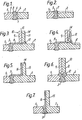
- FIG. 1 there is shown a butt weld between two components 1, 2 composed of dissimilar metals e.g. stainless steel and carbon steel respectively.
- the components 1, 2 are welded together using a weld metal 3 of a type suitable for welding the dissimilar metals.
- the manufacturers of the metals from which the components are made normally recommend suitable welding metals.
- the welding metal 3 is the same as the metal of component 1 or is a metal that does not form a knife-line corrodible combination with the metal of component 1.
- Normal design considerations, eg.g. strength require the weld to have the configuration shown, i.e. with the weld metal 3 filling the space between components 1, 2 with, perhaps, a slightly raised surface 4 in the vicinity of the weld.
- the upper surface 5 of the structure is exposed to a corrosive environment.
- the structure corrodes: it is here assumed for simplicity that the corrosion of component 1 and of the weld metal 3, is negligible compared with the corrosion of component 2.
- the corrosion takes two forms, firstly the normal corrosion of the surface 5 resulting in a reduction of thickness of component 2, and secondly, knife-line corrosion starting at the exposed junction 6 between the weld metal 3 and the metal of component 2.
- FIG. 2 A typical corroded structure is illustrated in Figure 2 where the original configuration is depicted by dotted lines. It is seen that, as the extent of knife-line corrosion occurring along the interface 7 between the two metals greatly exceeds that of the normal corrosion of the surface of component 2, the weld will fail at the junction of the dissimilar metals long before failure of the component 2 as a result of normal corrosion.
- the weld between the two components 1, 2 is of similar configuration, and has essentially the same load bearing region, as that of the weld in Figure 1.
- the weld con- fuguration differs however from that of Figure 1 in that the weld metal 3 is continued over the surface 8 of component 2 to contact and weld with one layer 9 of a bimetallic strip 10 coextensive with the length of the weld between components 1 and 2.
- Strip 10 is of welded laminate construction made, for example, by explosive welding; that layer 9 of the strip nearest the weld between components 1 and 2 is made of the same metal as component 1, or of the same metal as weld metal 3, or of a metal that does not form a knife-line corrodible combination with weld metal 3.
- the other layer 11 of the bimetallic strip 10 forms an appendage and is welded to component 2 by a weld 12 of the same metal as component 2 or of a metal that does not form a knife-layer corrodible combination with the metal of component 2.
- Layer 11 of the bimetallic strip 10 is formed from a metal, e.g. the same metal as component 2, that does not form a knife-line corrodible combination with the metal used for weld 12.
- the pathway between the metals that is liable t J knife-line corrosion is exposed to the corrosive environment at 13 and so has a length corresponding to the width of strip 10 plus the lateral distance between the strip 10 and the junction between component 2 and the weld metal 3 in the space between components 1 and 2.
- the strip 10 must be of such size, and displaced from the weld by such an extent that the knife-line corrosion will not reach the load bearing region of the weld between components 1 and 2 during the design life of the structure.
- the interface 14 between the metals at the appendage is laterally displaced from the line of the weld so that stress concentration produced by knife-line corrosion is displaced from the line of the weld.
- a laminated strip 10 may be incorporated into, and extending out of, the weld between components 1 and 2, with the layer 11 of the strip forming the appendage and being welded to component 2 with a weld metal 12.
- the metal of layer 11 is one that does not form a knife-line corrodible combination with weld metal 12 and with the metal of component 2.
- the appendage consists of a flange 15 integral with component 2 having an overlay 16 of the weld metal 3 on the side thereof nearer to component 1.
- a jointing component in accordance with the present invention may be desirable to fabricate, as a separate unit, a jointing component in accordance with the present invention by welding components of dissimilar metals together with a knife-line corrosion displacing member appropriately positioned, and then to weld the appropriate sides of this jointing component to the components made from the dissimilar metals with conventional welds.
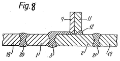
- FIG 8 Such an arrangement is shown in Figure 8 where two components 18, 19 made of dissimilar metals are connected by a jointing component fabricated in accordance with the configuration of Figure 3. Component 18 is welded to component 1 of the jointing component by weld metal 20 which does not form a knife-layer corrodible combination with either of the metals of components 1 and 18.
- Component 19 is welded to component 2 of the jointing components by weld metal 21.
- weld metal 21 is one that does not form a knife-line corrodible combination with either of the metals of components 2 and 19. This method of manufacture has the advantage that the special welds can be performed under more controlled conditions while only normal welds, between components 1 and 18, and between components 2 and 19, have to be performed on site.
- the structure is only exposed to a corrosive environment on one side thereof. It will be appreciated that where both surfaces are exposed to a corrosive environment, it is desirable that the exposed metal-metal junctions are displaced from the load bearing region of the weld on both exposed surfaces. Furthermore, in the foregoing description it is assumed that the corrosive environment has little or no effect on one of the metals employed: where both metals are liable to corrosion, the same principles of displacement of the exposed metal-metal junction apply.
- the thicknesses of the metal layer or layers used to displace the exposed junction should be such that normal corrosion does not remove this layer or layers at any point to such an extent that the layer or layers are eroded down to the interface between the metals before the knife-line corrosion has reached that point.
- the invention is of use wherever knife-line corrosion is liable to take place at a welded joint between dissimilar metals. It is of particular interest when welding stainless steel to carbon steel (in which case the weld metal is usually a stainless steel) but can also be used to advantage between other metal combinations, e.g. when welding carbon steel to nickel or to high nickel alloys.
- the invention is of particular merit in the construction of chemical plant, particularly for items that cannot be satisfactorily protected from corrosion by methods such as the application of a protective coating. Such instances arise where it is desired to use a sealed vessel and so maintenance operations on the interior is expensive and gives rise to loss of production.
- the invention is of particular utility in the construction of fermentation apparatus where the vessel is liable to corrosive attack by the fermentation medium which is often an aerated aqueous solution of inorganic salts.
- the use of welded joints for joining dissimilar metals, such as those forming knife-line corrodible combinations, instead of sealing systems where exposed contacting metal/metal joints are avoided, is desirable in such structures for ease of maintaining sterility.
- FIG. 9 A further example of the invention is illustrated in Figure 9 (which is not to scale).
- a ring 22 of 36 cm outside diameter and 10 mm thickness was welded to a short length of a pipe 2 of wall thickness 10 mm and nominal outside diameter 30 cm by a weld 12 so that 15 mm of the pipe 2 projected through ring 22.
- Ring 22, pipe 2, and weld 12 were all made of carbon steel type ASTM A106 B.
- a short length of a stainless steel (Sandvik 3 RE 60) pipe 1 of similar dimensions to pipe 2 was welded to the end of pipe 2 projecting through ring 22 using a weld metal 3 (Inconel 182) recommended for welding the stainless steel Sandvik 3 RE 60 to carbon steel.
- the resultant jointing section of pipe was then used to connect a pipe 19 to a stainless steel (Sandvik 3 RE 60) pipe 18 of similar dimensions to pipes 1 and 2.
- Pipe 2 was welded to pipe 19 by weld 21, and pipe 19 were of carbon steel type ASTM A 106 B.
- Pipe 1 was welded to pipe 18 using a weld 20 of stainless steel (AVESTA 3 RE 60 PW) recommended for welding together Sandvik Stainless steel 3 RE 60. No knife-line corrosion is liable to occur between AVESTA 3 RE 60 PW and Sandvik 3 RE 60.
- the welded structure was designed to have a service life of 15 years of exposure of the exterior surface of the pipes to an aerated aqueous mineral salt containing fermentation medium at 35°C.
- the expected corrosion of pipe 19 and pipe 2 is a reduction in wall thickness of about 3 mm.
- knife-line corrosion to the extent of about 30 mm between the stainless steel type 316 and the carbon steel is expected.
- the knife-line corrosion pathway from the metal/metal junction 25 exposed to the corrosive environment at the rim of ring 22 to the load bearing region of weld 3 has a length of about 45 mm, it is seen that the knife-line corrosion will not reach weld 3 during the intended service life of the structure.
Landscapes
- Engineering & Computer Science (AREA)
- Mechanical Engineering (AREA)
- Arc Welding In General (AREA)
- Materials For Medical Uses (AREA)
Claims (6)
1. Schweißkonstruktion für die Anwendung in einer korrodierenden Umgebung mit einer Schweißnaht (3) zwischen Teilen bzw. Werkstücken (1, 2), die aus Metallen in einer in Form von Messerschnitt- bzw. Messerlinien-korrosion korrodierbaren Kombination gebildet sind,
dadurch gekennzeichnet, daß zur Vermeidung einer von einer Messerschnittkorrosion zwischen den erwähnten Metallen herrührenden Schwächung des tragenden bzw. belasteten Bereichs der Schweißnaht (3)
eines (2) der Teile
einen Ansatz (15), der mit dem Teil (2) ein Stück bildet, aufweist oder
einen Ansatz (11) aufweist, der an dem einen Teil (2) mit einem Schweißmetall (12) angeschweißt ist, wobei das Schweißmetall (12) weder mit dem Metal-des Ansatzes (11) noch mit dem Metall des Teils (2), an dem der Ansatz (11) angeschweißt ist, eine in Form von Messerschnittkorrosion korrodierbare Kombination bildet, und
eine Metallschicht vorgesehen ist, die
die Oberfläche (8) des einen Teils (2) zwischen dem Ansatz (11; 15) und der Schweißnaht (3) zwischen den Teilen (1,2) und mindestens einen Teil der Oberfläche des Ansatzes (11; 15)
bedeckt und mit den Oberflächen, die sie bedeckt, zusammenhängend bzw. ohne Unterbrechung verschweißt ist, wobei das Metall der Metallschicht mit
dem Metall des einen Teils (2) und
dem Metall des Ansatzes (11; 15)
eine in Form von Messerschnittkorrosion korrodierbare Kombination bildet, so daß es sich
bei dem der Messerschnittkorrosion ausgesetzten Weg
von der korrodierenden Umgebung
zu derjenigen Metal-Metal-Grenzfläche (7) in dem tragenden Bereich der Schweißnaht (3) zwischen den Teilen (1, 2), die der Messerschnittkorrosion ausgesetzt ist,
um die durch zusammenhängendes Verschweißen gebildete Grenzfläche (14) zwischen der Metallschicht und den darunterliegenden Oberflächen des Ansatzes (11; 15) und des Teils (2) und
bei dem der korrodierenden Umgebung ausgesetzten Ende des erwähnten Weges um die Verbindung (13) zwischen der Metallschicht und dem Ansatz (11; 15) am Ende der Metallschicht
handelt,
wobei der Ansatz (11; 15) so angeordnet bzw. eingeortet ist und/oder eine solche Größe hat, daß die Länge des erwähnten Weges mindestens gleich der voraussichtlichen Ausdehnung der Messerschnittkorrosion entlang des Weges während der Soll-Lebensdauer der Schweißkonstruktion ist.
2. Schweißkonstruktion nach Anspruch 1, dadurch gekennzeichnet, daß
der Ansatz aus einer Metallschicht (11) eines en dem einen Teil (2) angeschweißten Bimetallstreifens (10) besteht,
wobei die eine Schicht (11) mit einem Schweißmetall (12), das weder mit dem Metall der einen Schicht (11) noch mit dem Metall des einen Teiles (2) eine in Form von Messerschnittkorrosion korrodierbare Kombination bildet, an dem Teil (2) angeschweißt ist,
während das Metall der anderen Schicht (9) des Bimetallstreifens (10) einen Teil der Metallschicht bildet, die sich von dem Ansatz (11) bis zu der Schweißnaht (3) zwischen den Teilen (1, 2) erstreckt.
3. Schweißkonstruktion nach Anspruch 1 oder 2, dadurch gekennzeichnet, daß das zur Bildung der Schweißnaht (3) zwischen den Teilen (1, 2) eingesetzte Metall ein Metall ist, das mit einem (1) der Teile keine in Form von Messerschnittkorrosion korrodierbare Kombination bildet.
4. Schweißkonstruktion nach einem der Ansprüche 1 bis 3, dadurch gekennzeichnet, daß das eine Teil (1) aus rostfreiem Stahl und das andere Teil (2) aus Kohlenstoffstahl bzw. unlegiertem Stahl hergestellt ist.
5. Schweißkonstruktion nach einem der Ansprüche 1 bis 4, dadurch gekennzeichnet, daß die Länge des der Messerschnittkorrosion ausgesetzten Weges mindestens 2 cm beträgt.
6. Schweißkonstruktion mit
einem aus einem ersten Metal gebildeten, ersten Bauglied (18) und
einem aus einem zweiten Metall gebildeten, zweiten Bauglied (19),
dadurch gekennzeichnet, daß
das erste (18) und das zweite (19) Bauglied durch eine Schweißverbindungskonstruktion nach einem der Ansprüche 1 bis 5 miteinander verbunden sind, wobei die Verbindungskonstruktion
ein aus dem ersten Metall begildetes, erstes Teil (1) das an
einem aus dem zweiten Metall gebildeten, zweiten Teil (2) angeschweißt ist,
aufweist,
wobei das erste Bauglied (18) mit einem Schweißmetall (20), das mit dem ersten Metall keine in Form von Messerschnittkorrosion korrodierbare Kombination bildet, an dem ersten Teil (1) angeschweißt ist, und
das zweite Bauglied (19) mit einem Schweißmetall (21), das mit dem zweiten Metall keine in Form von Messerschnittkorrosion korrodierbare Kombination bildet, an dem zweiten Teil (2) angeschweißt ist.
Applications Claiming Priority (2)
| Application Number | Priority Date | Filing Date | Title |
|---|---|---|---|
| GB7910579 | 1979-03-27 | ||
| GB7910579 | 1979-03-27 |
Publications (2)
| Publication Number | Publication Date |
|---|---|
| EP0016645A1 EP0016645A1 (de) | 1980-10-01 |
| EP0016645B1 true EP0016645B1 (de) | 1982-12-22 |
Family
ID=10504147
Family Applications (1)
| Application Number | Title | Priority Date | Filing Date |
|---|---|---|---|
| EP80300875A Expired EP0016645B1 (de) | 1979-03-27 | 1980-03-20 | Geschweisste Strukturen |
Country Status (3)
| Country | Link |
|---|---|
| EP (1) | EP0016645B1 (de) |
| JP (1) | JPS55133895A (de) |
| NO (1) | NO800882L (de) |
Families Citing this family (4)
| Publication number | Priority date | Publication date | Assignee | Title |
|---|---|---|---|---|
| JP6803787B2 (ja) * | 2017-03-29 | 2020-12-23 | 三菱パワー株式会社 | 溶接継手の破壊再現方法、溶接継手の寿命予測方法、溶接継手の破壊再現装置及び溶接継手の寿命予測装置 |
| CN106944771B (zh) * | 2017-04-21 | 2019-05-17 | 浙江申轮水泥机械制造有限公司 | 一种堆焊焊条的制备方法 |
| CN110253112B (zh) * | 2019-07-12 | 2022-09-13 | 中船桂江造船有限公司 | 一种917钢板+1Cr18Ni9Ti异种钢焊接方法 |
| CN110253109B (zh) * | 2019-07-12 | 2022-11-15 | 中船桂江造船有限公司 | 一种CCSB钢+1Cr18NI9TI异种钢的焊接方法 |
Family Cites Families (1)
| Publication number | Priority date | Publication date | Assignee | Title |
|---|---|---|---|---|
| DD99816A1 (de) * | 1972-08-21 | 1973-08-20 |
-
1980
- 1980-03-20 EP EP80300875A patent/EP0016645B1/de not_active Expired
- 1980-03-26 NO NO800882A patent/NO800882L/no unknown
- 1980-03-27 JP JP3963680A patent/JPS55133895A/ja active Pending
Also Published As
| Publication number | Publication date |
|---|---|
| NO800882L (no) | 1980-09-29 |
| JPS55133895A (en) | 1980-10-18 |
| EP0016645A1 (de) | 1980-10-01 |
Similar Documents
| Publication | Publication Date | Title |
|---|---|---|
| EP0150041A2 (de) | Korrosionswiderstandsfähiges Stahlrohr und Verfahren zu seiner Herstellung | |
| JP3327928B2 (ja) | 耐蝕性及び耐火性のパイプシステム | |
| KR100325783B1 (ko) | 스텐레스강 튜브와 지르코늄 합금 튜브를 용접하는데 사용하는중간 조인트 | |
| JPS622903B2 (de) | ||
| EP0016645B1 (de) | Geschweisste Strukturen | |
| US4318966A (en) | Welded structures | |
| GB2264764A (en) | Corrosion resistant pipe | |
| JPH02186196A (ja) | 煙道ガス脱硫装置等の腐食防止方法 | |
| JPH10175076A (ja) | 金属基材表面への薄金属シート被覆方法 | |
| EP1493968B1 (de) | Membranwand | |
| JP2003136286A (ja) | 配管用炭素鋼鋼管溶融亜鉛メッキ材の、電気溶接接続における配管芯、間隙合わせ機能付き内面腐食防止被覆短管。 | |
| JPS6030588A (ja) | 異材管溶接継手 | |
| JPS6219953B2 (de) | ||
| Eun | Welding and heat treatment requirements in Shop and Field | |
| JPS6335333B2 (de) | ||
| SU989224A1 (ru) | Узел герметизации проходки трубопровода | |
| JP3041770U (ja) | ボイラ伝熱管溶接部の構造 | |
| JPS6045033B2 (ja) | 溶接鋭敏化部の応力腐食割れ防止方法 | |
| JPH0212678B2 (de) | ||
| JPH0659553B2 (ja) | ライニング管の溶接方法 | |
| JPS60373Y2 (ja) | 防食被覆体 | |
| JPH0510557B2 (de) | ||
| JP2013174296A (ja) | 継手構造及び継手方法 | |
| JPH07279191A (ja) | チタン被覆防食構造 | |
| JPH0252155B2 (de) |
Legal Events
| Date | Code | Title | Description |
|---|---|---|---|
| PUAI | Public reference made under article 153(3) epc to a published international application that has entered the european phase |
Free format text: ORIGINAL CODE: 0009012 |
|
| AK | Designated contracting states |
Designated state(s): BE DE FR GB IT NL SE |
|
| 17P | Request for examination filed | ||
| RAP1 | Party data changed (applicant data changed or rights of an application transferred) |
Owner name: IMPERIAL CHEMICAL INDUSTRIES PLC |
|
| GRAA | (expected) grant |
Free format text: ORIGINAL CODE: 0009210 |
|
| AK | Designated contracting states |
Designated state(s): GB |
|
| GBPC | Gb: european patent ceased through non-payment of renewal fee | ||
| PG25 | Lapsed in a contracting state [announced via postgrant information from national office to epo] |
Ref country code: GB Effective date: 19881118 |
|
| PLBE | No opposition filed within time limit |
Free format text: ORIGINAL CODE: 0009261 |
|
| STAA | Information on the status of an ep patent application or granted ep patent |
Free format text: STATUS: NO OPPOSITION FILED WITHIN TIME LIMIT |