EP0014438B1 - Eckverbindung für einen aus Hohlprofilabschnitten zusammensetzbaren Rahmen - Google Patents
Eckverbindung für einen aus Hohlprofilabschnitten zusammensetzbaren Rahmen Download PDFInfo
- Publication number
- EP0014438B1 EP0014438B1 EP80100480A EP80100480A EP0014438B1 EP 0014438 B1 EP0014438 B1 EP 0014438B1 EP 80100480 A EP80100480 A EP 80100480A EP 80100480 A EP80100480 A EP 80100480A EP 0014438 B1 EP0014438 B1 EP 0014438B1
- Authority
- EP
- European Patent Office
- Prior art keywords
- hollow profile
- profile sections
- corner
- clamping
- fact
- Prior art date
- Legal status (The legal status is an assumption and is not a legal conclusion. Google has not performed a legal analysis and makes no representation as to the accuracy of the status listed.)
- Expired
Links
- 229910000746 Structural steel Inorganic materials 0.000 claims abstract 9
- 239000002184 metal Substances 0.000 claims description 2
- 229910052751 metal Inorganic materials 0.000 claims description 2
- 238000005058 metal casting Methods 0.000 claims description 2
- 230000001771 impaired effect Effects 0.000 description 1
- 238000003780 insertion Methods 0.000 description 1
- 230000037431 insertion Effects 0.000 description 1
- 238000004519 manufacturing process Methods 0.000 description 1
- 230000002093 peripheral effect Effects 0.000 description 1
- 238000007789 sealing Methods 0.000 description 1
Images

Classifications
-
- E—FIXED CONSTRUCTIONS
- E06—DOORS, WINDOWS, SHUTTERS, OR ROLLER BLINDS IN GENERAL; LADDERS
- E06B—FIXED OR MOVABLE CLOSURES FOR OPENINGS IN BUILDINGS, VEHICLES, FENCES OR LIKE ENCLOSURES IN GENERAL, e.g. DOORS, WINDOWS, BLINDS, GATES
- E06B3/00—Window sashes, door leaves, or like elements for closing wall or like openings; Layout of fixed or moving closures, e.g. windows in wall or like openings; Features of rigidly-mounted outer frames relating to the mounting of wing frames
- E06B3/96—Corner joints or edge joints for windows, doors, or the like frames or wings
- E06B3/964—Corner joints or edge joints for windows, doors, or the like frames or wings using separate connection pieces, e.g. T-connection pieces
- E06B3/968—Corner joints or edge joints for windows, doors, or the like frames or wings using separate connection pieces, e.g. T-connection pieces characterised by the way the connecting pieces are fixed in or on the frame members
- E06B3/98—Corner joints or edge joints for windows, doors, or the like frames or wings using separate connection pieces, e.g. T-connection pieces characterised by the way the connecting pieces are fixed in or on the frame members the connecting pieces being specially adapted for drawing the frame members towards each other
- E06B3/982—Mitre joints
-
- F—MECHANICAL ENGINEERING; LIGHTING; HEATING; WEAPONS; BLASTING
- F16—ENGINEERING ELEMENTS AND UNITS; GENERAL MEASURES FOR PRODUCING AND MAINTAINING EFFECTIVE FUNCTIONING OF MACHINES OR INSTALLATIONS; THERMAL INSULATION IN GENERAL
- F16B—DEVICES FOR FASTENING OR SECURING CONSTRUCTIONAL ELEMENTS OR MACHINE PARTS TOGETHER, e.g. NAILS, BOLTS, CIRCLIPS, CLAMPS, CLIPS OR WEDGES; JOINTS OR JOINTING
- F16B12/00—Jointing of furniture or the like, e.g. hidden from exterior
- F16B12/10—Jointing of furniture or the like, e.g. hidden from exterior using pegs, bolts, tenons, clamps, clips, or the like
-
- F—MECHANICAL ENGINEERING; LIGHTING; HEATING; WEAPONS; BLASTING
- F16—ENGINEERING ELEMENTS AND UNITS; GENERAL MEASURES FOR PRODUCING AND MAINTAINING EFFECTIVE FUNCTIONING OF MACHINES OR INSTALLATIONS; THERMAL INSULATION IN GENERAL
- F16B—DEVICES FOR FASTENING OR SECURING CONSTRUCTIONAL ELEMENTS OR MACHINE PARTS TOGETHER, e.g. NAILS, BOLTS, CIRCLIPS, CLAMPS, CLIPS OR WEDGES; JOINTS OR JOINTING
- F16B12/00—Jointing of furniture or the like, e.g. hidden from exterior
- F16B12/44—Leg joints; Corner joints
- F16B12/50—Metal corner connections
- F16B2012/505—Metal corner connections having a corner insert which is inserted in mitered profiled members
Definitions
- the invention relates to a corner connection for a frame which can be assembled from hollow profile sections, in which a corner angle with its legs is inserted into the cavities of the hollow profile sections to be connected and by means of tensioning elements which are supported in receptacles of the hollow profile sections and the legs of the corner angle, under tension against the ends the hollow profile sections is clamped.
- Such a corner connection is e.g. known from DE-U-7333552.
- the corner brackets are provided with threaded holes into which clamping screws can be inserted.
- the clamping screws are designed as hollow screws provided with an internal thread, which are supported in receptacles of the hollow profile sections to be connected to one another and into which pressure screws provided with a support foot can be inserted. With these pressure screws, the corner angle is clamped transversely to the longitudinal axes of the hollow profile sections. With this bracing, however, it is not ensured that the two hollow profile sections with their abutting abutting surfaces are braced without joints against one another.
- Tensioning of the hollow profile sections in the area of their abutting abutting surfaces is achieved with a corner connection, as shown in DE-U-19 58 354.
- threaded holes are provided in the corner bracket, into which the clamping screws can be screwed.
- the clamping screws have frustoconical heads with which they are guided in receptacles of the hollow profile sections. When the clamping screws are tightened, the hollow profile sections are shifted in the direction of the corner formed and thus firmly clamped together in the area of their abutting surfaces.
- clamping elements are designed as clamping eccentrics which are guided by means of guide disks in the receptacles of the hollow profile sections and are supported with the eccentric parts at least on the sides facing away from the corner on clamping surfaces of the legs of the corner bracket.
- the corner bracket only needs clamping surfaces for the eccentric parts of the clamping eccentric, which can be attached during the production of the corner bracket without additional work steps.
- the guide disks of the clamping eccentrics are inserted flush in the receptacles of the hollow profile sections and do not change this position even when they are rotated, so that the receptacles can certainly be introduced at locations on the hollow profile sections which later accommodate a seal, a disk, a plate or the like.
- the clamping surfaces for the eccentric parts of the clamping eccentrics can be formed in the simplest manner at the corner angle in that the clamping surfaces are formed by webs or grooves of the corner angle running transversely to the longitudinal axes of the legs.
- the guide disks of the clamping eccentric are held in receptacles of the hollow profile sections designed as bores and that the eccentric parts of the clamping eccentric are guided between two webs or grooves running transversely to the longitudinal axes of the legs .
- the guidance and the support of the clamping eccentric can be achieved according to a further embodiment in that the guide disks of the clamping eccentrics are guided in receptacles designed as elongated holes, which run transversely to the longitudinal axes of the hollow profile sections, and in that the eccentric parts are held in receptacles designed as sleeves or bores Leg of the corner bracket are held.
- the rotation of the clamping eccentric is facilitated by the fact that the guide disks of the clamping eccentric with tool holders, e.g. with hexagon socket.
- the hold of the clamping eccentric in the receptacles of the hollow profile sections can be improved according to a further development in that the guide disks of the clamping eccentric pass into the eccentric parts via retaining collars.
- the receptacles in the hollow profile sections are designed as a keyhole for introducing the clamping eccentric with a retaining collar.
- the corner connection with the clamping eccentrics according to the invention can be designed in such a way that the hollow profile sections are mitred and clamped directly against one another.
- the design of the corner connection can also be designed so that the Eckwin kel has a corner profile part corresponding to the hollow profile sections and that the cross-sectionally cut to their longitudinal axis hollow profile sections are braced against this corner profile part.
- the clamping positions of the clamping eccentrics can be determined in that the eccentric parts are provided on their peripheral sides with a toothing in which the teeth and tooth gaps are aligned parallel to the central axis of the eccentric parts.
- the gears are more or less pressed into the clamping surfaces of the corner bracket, so that unintentional loosening, i.e. Twisting, the clamping eccentric is prevented.
- the corner connection according to the invention is not limited to certain cross sections of the hollow profile sections.
- the cross section of the hollow profile sections depends on the use of the assembled frame. It is essential for the corner connection according to the invention that the hollow profile sections 10 have a cavity 11, as shown in FIG. It is entirely possible that this cavity is also open on one side, it only has to be such that one leg of the corner angle 30 provided for connection cannot be moved transversely to the longitudinal axis of the hollow profile section 10.
- the two hollow profile sections 10 to be connected to one another according to FIG. 1 are mitred, as shown by the abutting surfaces 12 at an angle of 45 °.
- the corner bracket 30 is inserted with its legs 31 and 32 into the cavities 11 of the hollow profile sections 10.
- the legs 31 and 32 are supported on the walls 13, 15 and 16, while the transverse webs 33, 34 and 36 and 37 are supported on the wall 17.
- the diagonally directed web 39 is supported on the wall 17 in the region of the abutting surfaces 12. In this way, the corner angle 30 in both hollow profile sections 10 can no longer be adjusted transversely to the longitudinal axes of the hollow profile sections 10. However, the hollow profile sections 10 which are at right angles to one another can still be moved and braced against one another.
- receptacles 14 designed as bores are made in the wall 13 of the hollow profile sections 10. Eccentric 20 are inserted into these holes. These clamping eccentrics 20 are rotatably guided with their guide disks 21 in the receptacles 14.
- the guide disks 21 are provided on the end face with a hexagon socket 22 as a tool holder, which enables the clamping eccentrics 20 to be rotated.
- the guide disks 21 pass over retaining collars 23 into eccentric parts 24 which are offset with their central axes by a predetermined amount with respect to the central axes of the guide disks 21.
- the receptacles 14 are designed as a keyhole so that the clamping eccentric 20 can be inserted with the retaining collar 23 and held on the hollow profile sections 10.
- the eccentric parts 24 of the clamping eccentrics 20 protrude into the transverse receptacles 35 and 38 of the corner bracket 30, which are formed by the web pairs 33 and 34 or 36 and 37.
- the arrangement of the receptacles 14 in the hollow profile sections 10 and the receptacles 35 and 38 in the corner bracket 30 is selected in connection with the design of the clamping eccentric 20 so that twisting of the clamping eccentric 20 and the resulting support of the eccentric parts 24 on the webs 33 and 36, the hollow profile sections 10 are braced in the area of their abutting surfaces 12.
- the counter pressure is transmitted from the guide disks 21 of the clamping eccentrics 20 to the walls of the receptacles 14 and thus to the hollow profile sections 10, specifically on the sides facing the abutting surfaces 12. In this way, the abutting surfaces 12 can be connected to one another seamlessly under tension.
- the guide disks 21 are flush with the outer sides of the walls 13 of the hollow profile sections 10, so that the introduction of sealing elements, disks or the like is not impaired in the subsequent outer grooves of the hollow profile sections.
- FIG. 2 shows in section a different type of guidance and support of the clamping eccentric 20.
- the receptacle 14 in the wall 13 of the hollow profile section 10 is designed as an elongated hole which runs transversely to the longitudinal axis of the hollow profile section.
- the width of the elongated hole corresponds to the diameter of the guide disk 21 of the clamping eccentric 20, which this time merges directly into the eccentric part 24.
- the eccentric part 24 projects into a clamping sleeve 40 of the corner bracket 30, which is matched with its inner receptacle to the outer diameter of the eccentric part 24.
- the eccentric part 24 is provided with teeth 25, the teeth and tooth gaps of which are aligned parallel to the central axis of the eccentric part 24.
- the eccentric part 24 of the clamping eccentric 20 transmits an adjusting movement running in the longitudinal axis of the hollow profile section 10 to the corner angle 30.
- the toothing 25 is supported on the clamping sleeve 40 on the side facing away from the abutting surface.
- the teeth of the gearing. 25 more or less cling to the Clamping sleeve 40 and ensure that the set position of the clamping eccentric 20 does not unintentionally come loose again.
- a corner angle 30 which has a corner profile part 50 which corresponds in cross section to the cross section of the hollow profile sections 10 and completes the corner of the hollow profile sections 10 which are cut to length with respect to the longitudinal axes.
- the abutting surfaces 12 of the hollow profile sections 10 are braced against the shoulders 42 and 44 between the corner profile part 50 and the legs 41 and 43 of the corner bracket 30.
- the clamping eccentrics 20, as used in FIG. 2 are again guided in elongated holes which run transversely to the longitudinal axes of the hollow profile sections 10 and project with their eccentric parts 24 into the receptacles 45 and 46 in the legs 41 and 43 of the corner bracket 30 .
- the legs 41 and 43 are again adapted in cross section to the cross section of the cavities of the interconnecting hollow profile sections.
Landscapes
- Engineering & Computer Science (AREA)
- General Engineering & Computer Science (AREA)
- Mechanical Engineering (AREA)
- Civil Engineering (AREA)
- Structural Engineering (AREA)
- Mutual Connection Of Rods And Tubes (AREA)
- Joining Of Corner Units Of Frames Or Wings (AREA)
Description
- Die Erfindung betrifft eine Eckverbindung für einen aus Hohlprofilabschnitten zusammensetzbaren Rahmen, bei der ein Eckwinkel mit seinen Schenkeln in die Hohlräume der miteinander zu verbindenden Hohlprofilabschnitte eingeführt und mittels Spannelementen, die sich in Aufnahmen der Hohlprofilabschnitte und der Schenkel des Eckwinkels abstützen, unter Spannung gegen die Enden der Hohlprofilabschnitte verspannt ist.
- Eine derartige Eckverbindung ist z.B. aus dem DE-U-7333552 bekannt. Bei dieser bekannten Eckverbindung sind die Eckwinkel mit Gewindebohrungen versehen, in die Klemmschrauben einführbar sind. Die Klemmschrauben sind als mit einem Innengewinde versehene Hohlschrauben ausgebildet, die in Aufnahmen der miteinander zu verbindenden Hohlprofilabschnitte abgestützt sind und in die mit einem Stützfuß versehene Andrückschrauben einführbar sind. Mit diesen Andrückschrauben wird der Eckwinkel quer zu den Längsachsen der Hohlprofilabschnitte verspannt. Mit dieser Verspannung ist aber nicht sichergestellt, daß die beiden Hohlprofilabschnitte mit ihren aufeinander treffenden Stoßflächen gegeneinander fugenlos verspannt sind.
- Eine Verspannung der Hohlprofilabschnitte im Bereich ihrer aufeinander treffenden Stoßflächen wird bei einer Eckverbindung erreicht, wie sie in dem DE-U-19 58 354 gezeigt ist. Auch hier sind in dem Eckwinkel Gewindebohrungen vorgesehen, in die Spannschrauben einschraubbar sind. Die Spannschrauben weisen jedoch kegelstumpfförmige Köpfe auf, mit denen sie in Aufnahmen der Hohlprofilabschnitte geführt sind. Beim Anziehen der Spannschrauben werden die Hohlprofilabschnitte in Richtung der gebildeten Ecke verschoben und so im Bereich ihrer Stoßflächen fest miteinander verspannt.
- Diese bekannte Eckverbindung erfordert jedoch einen teuren Eckwinkel mit Gewindebohrungen und spezielle Spannschrauben, die immer mehr oder weniger über die Wände der Hohlprofilabschnitte mit den Aufnahmen für die Köpfe der Spannschrauben vorstehen.
- Aus der DE-A 1 949 246 sind derartige Eckverbindungen bekannt, bei denen Hohlprofile mittels Exzenterspanneinrichtungen an einem Eckwinkel festgeklemmt werden, wobei jedoch die konstruktive Ausführung aufwendig ist.
- Es ist Aufgabe der Erfindung, eine Eckverbindung der eingangs erwänten Art so zu verbessern, daß unter Beibehaltung einer eindeutigen Verspannung der Hohlprofilabschnitte im Eckbereich ein Eckwinkel ohne Gewindebohrungen verwendet werden kann und daß die Spannelemente unabhängig von ihrer Spannstellung bündig in die zugeordneten Wände der Hohlprofilabschnitte mit den Aufnahmen für diese Spannelemente eingesetzt werden können.
- Dies wird erfindungsgemäß dadurch erreicht, daß die Spannelemente als Spannexzenter ausgebildet sind, die mittels Führungsscheiben in den Aufnahmen der Hohlprofilabschnitte geführt und mit den Exzenterteilen zumindest auf den der Ecke abgekehrten Seiten an Spannflächen der Schenkel des Eckwinkels abgestützt sind.
- Der Eckwinkel benötigt bei dieser Eckverbindung nur noch Spannflächen für die Exzenterteile der Spannexzenter, die bei der Herstellung der Eckwinkel ohne zusätzliche Arbeitsgänge angebracht werden können. Die Führungsscheiben der Spannexzenter sind bündig in die Aufnahmen der Hohlprofilabschnitte eingesetzt und verändern diese Stellung auch bei ihrer Verdrehung nicht, so daß die Aufnahmen durchaus an Stellen der Hohlprofilabschnitte eingebracht werden können, die später eine Dichtung, eine Scheibe, eine Platte oder dgl. aufnehmen.
- In einfachster Weise lassen sich die Spannflächen für die Exzenterteile der Spannexzenter an dem Eckwinkel dadurch bilden, daß die Spannflächen durch quer zu den Längsachsen der Schenkel verlaufende Stege oder Nuten des Eckwinkels gebildet sind.
- Für die Führung und Abstützung der Spannexzenter kann nach einer Ausgestaltung vorgesehen sein, daß die Führungsscheiben der Spannexzenter in als Bohrungen entsprechenden Durchmesser ausgebildeten Aufnahmen der Hohlprofilabschnitte gehalten sind und daß die Exzenterteile der Spannexzenter zwischen zwei quer zu den Längsachsen der Schenkel verlaufenden Stegen oder Nuten geführt sind.
- Die Führung und die Abstützung der Spannexzenter können nach einer weiteren Ausgestaltung auch dadurch erreicht werden, daß die Führungsscheiben der Spannexzenter in quer zu den Längsachsen der Hohlprofilabschnitte verlaufenden, als Langlöcher ausgebildeten Aufnahmen geführt sind und daß die Exzenterteile in als Hülsen oder als Bohrungen ausgebildeten Aufnahmen der Schenkel des Eckwinkels gehalten sind.
- Die Verdrehung der Spannexzenter wird dadurch erleichtert, daß die Führungsscheiben der Spannexzenter mit Werkzeugaufnahmen, z.B. mit Innensechskant, versehen sind.
- Der Halt der Spannexzenter in den Aufnahmen der Hohlprofilabschnitte läßt sich nach einer Weiterbildung dadurch verbessern, daß die Führungsscheiben der Spannexzenter über Haltebunde in die Exzenterteile übergehen. Dabei ist zur besseren Einführung der Spannexzenter vorgesehen, daß die Aufnahmen in den Hohlprofilabschnitten als Schlüsselloch zur Einführung der Spannexzenter mit Haltebund ausgebildet sind.
- Die Eckverbindung mit den erfindungsgemäßen Spannexzentern kann nach einer Ausgestaltung so ausgeführt sein, daß die Hohlprofilabschnitte auf Gehrung geschnitten und unmittelbar aufeinanderstoßend verspannt sind.
- Die Ausgestaltung der Eckverbindung kann jedoch auch so ausgeführt sein, daß der Eckwinkel ein den Hohlprofilabschnitten entsprechendes Eckprofilteil aufweist und daß die quer zu ihren Längsachsen abgelängten Hohlprofilabschnitte gegen dieses Eckprofilteil verspannt sind.
- Die Spannstellungen der Spannexzenter lassen sich nach einer Ausgestaltung dadurch festlegen, daß die Exzenterteile auf ihren Umfangsseiten mit einer Verzahnung versehen sind, bei der die Zähne und Zahnlücken parallel zur Mittelachse der Exzenterteile ausgerichtet sind. Die Verzahnungen drücken sich mehr oder weniger in die Spannflächen des Eckwinkels ein, so daß ein unbeabsichtigtes Lösen, d.h. Verdrehen, der Spannexzenter verhindert ist.
- Die Spannexzenter können als billige Metallgußteile oder Metalldrehteile hergestellt werden. Die Erfindung wird anhand von verschiedenen, in den Zeichnungen dargestellten Ausführungsbeispielen näher erläutert. Es zeigen :
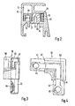
- Figur 1 in Explosionsdarstellung eine erfindungsgemäße Eckverbindung mit auf Gehrung geschnittenen Hohlprofilabschnitten,
- Figur 2 im Querschnitt eine Spannstelle einer Eckverbindung mit anders gestaltetem Eckwinkel und
- Figuren 3 und 4 in zwei verschiedenen Ansichten einen Eckwinkel mit einem Eckprofilteil zur Verbindung von zwei senkrecht zu ihren Längsachsen abgelängten Hohlprofilabschnitten.
- Die erfindungsgemäße Eckverbindung ist nicht auf bestimmte Querschnitte der Hohlprofilabschnitte beschränkt. Der Querschnitt der Hohlprofilabschnitte richtet sich nach dem Einsatz des zusammensetzbaren Rahmens. Wesentlich für die erfindungsgemäße Eckverbindung ist, daß die Hohlprofilabschnitte 10 einen Hohlraum 11 aufweisen, wie Figur 1 zeigt. Dabei ist es durchaus möglich, daß dieser Hohlraum auch einseitig offen ist, er muß nur so beschaffen sein, daß darin ein Schenkel des zur Verbindung vorgesehenen Eckwinkels 30 quer zur Längsachse des Hohlprofilabschnittes 10 nicht verschiebbar ist.
- Die beiden miteinander zu verbindenden Hohlprofilabschnitte 10 nach Figur 1 sind auf Gehrung geschnitten, wie die im Winkel von 45° stehenden Stoßflächen 12 zeigen. Der Eckwinkel 30 wird mit seinen Schenkeln 31 und 32 in die Hohlräume 11 der Hohlprofilabschnitte 10 eingesteckt. Dabei stützen sich die Schenkel 31 und 32 an den Wänden 13, 15 und 16 ab, während die quer verlaufenden Stege 33, 34 bzw. 36 und 37 an der Wand 17 abstützen. Der diagonal gerichtete Steg 39 stützt sich im Bereich der Stoßflächen 12 an der Wand 17 ab. Auf diese Weise ist der Eckwinkel 30 in beiden Hohlprofilabschnitten 10 nicht mehr quer zu den Längsachsen der Hohlprofilabschnitte 10 verstellbar. Die im rechten Winkel zueinander stehenden Hohlprofilabschnitte 10 können jedoch noch gegeneinander bewegt und verspannt werden. Um diese Verspannung ausführen zu können, sind in der Wand 13 der Hohlprofilabschnitte 10 als Bohrungen ausgebildete Aufnahmen 14 eingebracht. In diese Bohrungen werden Spannexzenter 20 eingesetzt. Diese Spannexzenter 20 sind mit ihren Führungsscheiben 21 in den Aufnahmen 14 verdrehbar geführt. Die Führungsscheiben 21 sind stirnseitig mit einem Innensechskant 22 als Werkzeugaufnahme versehen, die das Verdrehen der Spannexzenter 20 ermöglicht. Die Führungsscheiben 21 gehen über Haltebunde 23 in Exzenterteile 24 über, die mit ihren Mittelachsen um einen vorgegebenen Betrag gegenüber den Mittelachsen der Führungsscheiben 21 versetzt sind. Die Aufnahmen 14 sind als Schlüsselloch ausgebildet, so daß die Spannexzenter 20 mit dem Haltebund 23 eingeführt und an den Hohlprofilabschnitten 10 gehalten werden können. Die Exzenterteile 24 der Spannexzenter 20 ragen in die Queraufnahmen 35 und 38 des Eckwinkels 30, die durch die Stegpaare 33 und 34 bzw. 36 und 37 gebildet werden. Die Anordnung der Aufnahmen 14 in den Hohlprofilabschnitten 10 und der Aufnahmen 35 und 38 in dem Eckwinkel 30 ist in Verbindung mit der Ausbildung der Spannexzenter 20 so gewählt, daß durch Verdrehung der Spannexzenter 20 und der dabei auftretenden Abstützung der Exzenterteile 24 an den Stegen 33 und 36 die Hohlprofilabschnitte 10 im Bereich ihrer Stoßflächen 12 verspannt werden. Der Gegendruck wird von den Führungsscheiben 21 der Spannexzenter 20 auf die Wandungen der Aufnahmen 14 und damit auf die Hohlprofilabschnitte 10 übertragen und zwar auf den den Stoßflächen 12 zugekehrten Seiten. Auf diese Weise lassen sich die Stoßflächen 12 unter Spannung fugenlos miteinander verbinden. Die Führungsscheiben 21 schließen bündig mit den Außenseiten der Wände 13 der Hohlprofilabschnitte 10 ab, so daß das Einbringen von Dichtungselementen, Scheiben oder dgl. in die anschließenden Außennuten der Hohlprofilabschnitte nicht beeinträchtigt ist.
- Figur 2 zeigt im Schnitt eine andersartige Führung und Abstützung des Spannexzenters 20. Die Aufnahme 14 in der Wand 13 des Hohlprofilabschnittes 10 ist als Langloch ausgebildet, das quer zur Längsachse des Hohlprofilabschnittes verläuft. Die Breite des Langloches entspricht dem Durchmesser der Führungsscheibe 21 des Spannexzenters 20, die diesmal direkt in das Exzenterteil 24 übergeht. Das Exzenterteil 24 ragt in eine Spannhülse 40 des Eckwinkels 30, die mit ihrer Innenaufnahme auf den Außendurchmesser des Exzenterteils 24 abgestimmt ist. Auf dem Außenumfang ist das Exzenterteil 24 mit einer Verzahnung 25 versehen, deren Zähne und Zahnlücken parallel zur Mittelachse des Exzenterteiles 24 ausgerichtet sind..Bei einer Verdrehung des Spannexzenters 20 wird die Führungsscheibe 21 in der als Langloch ausgebildeten Aufnahme 14 quer zum Hohlprofilabschnitt 10 verstellt. Das Exzenterteil 24 des Spannexzenters 20 überträgt dabei eine in der Längsachse des Hohlprofilabschnittes 10 verlaufende Stellbewegung auf den Eckwinkel 30. Die Verzahnung 25 stützt sich dabei an der der Stoßfläche abgekehrten Seite an der Spannhülse 40 ab. Die Zähne der Verzahnung. 25 verkrallen sich mehr oder weniger an der Spannhülse 40 und stellen so sicher, daß sich die eingestellte Stellung des Spannexzenters 20 nicht unbeabsichtigt wieder löst.
- In den Ansichten nach Figur 3 und 4 ist ein Eckwinkel 30 gezeigt, der ein Eckprofilteil 50 aufweist, welches im Querschnitt dem Querschnitt der Hohlprofilabschnitte 10 entspricht und die Ecke der quer zu den Längsachsen abgelängten Hohlprofilabschnitte 10 vervollständigt. Die Stoßflächen 12 der Hohlprofilabschnitte 10 werden gegen die Absätze 42 und 44 zwischen dem Eckprofilteil 50 und den Schenkeln 41 und 43 des Eckwinkels 30 verspannt. Die Spannexzenter 20, wie sie in Figur 2 eingesetzt sind, werden wieder in als quer zu den Längsachsen der Hohlprofilabschnitte 10 verlaufenden Langlöchern geführt und ragen mit ihren Exzenterteilen 24 in die als Sackbohrungen 45 und 46 in die Schenkel 41 und 43 des Eckwinkels 30 eingebrachten Aufnahmen. Die Schenkel 41 und 43 sind im Querschnitt wieder an den Querschnitt der Hohlräume der miteinander verbindenden Hohlprofilabschnitte angepaßt.
Claims (11)
Priority Applications (1)
| Application Number | Priority Date | Filing Date | Title |
|---|---|---|---|
| AT80100480T ATE2351T1 (de) | 1979-02-05 | 1980-01-31 | Eckverbindung fuer einen aus hohlprofilabschnitten zusammensetzbaren rahmen. |
Applications Claiming Priority (2)
| Application Number | Priority Date | Filing Date | Title |
|---|---|---|---|
| DE7903124 | 1979-02-05 | ||
| DE7903124U | 1979-02-05 |
Publications (2)
| Publication Number | Publication Date |
|---|---|
| EP0014438A1 EP0014438A1 (de) | 1980-08-20 |
| EP0014438B1 true EP0014438B1 (de) | 1983-01-26 |
Family
ID=6700763
Family Applications (1)
| Application Number | Title | Priority Date | Filing Date |
|---|---|---|---|
| EP80100480A Expired EP0014438B1 (de) | 1979-02-05 | 1980-01-31 | Eckverbindung für einen aus Hohlprofilabschnitten zusammensetzbaren Rahmen |
Country Status (2)
| Country | Link |
|---|---|
| EP (1) | EP0014438B1 (de) |
| AT (1) | ATE2351T1 (de) |
Cited By (1)
| Publication number | Priority date | Publication date | Assignee | Title |
|---|---|---|---|---|
| CN107654168A (zh) * | 2017-09-19 | 2018-02-02 | 浙江长兴科创金属制品有限公司 | 一种铝合金门窗转角 |
Families Citing this family (2)
| Publication number | Priority date | Publication date | Assignee | Title |
|---|---|---|---|---|
| US4547986A (en) * | 1982-12-27 | 1985-10-22 | Nielsen Moulding Design Corp. | Framing system |
| DE3726594A1 (de) * | 1987-08-10 | 1989-02-23 | Erbsloeh Julius & August | Eckverbindung fuer hohlprofil-rahmen |
Family Cites Families (2)
| Publication number | Priority date | Publication date | Assignee | Title |
|---|---|---|---|---|
| AT218693B (de) * | 1959-06-16 | 1961-12-11 | Nicola Alloggio | Zerlegbares Gestell, insbesondere zum Herstellen von Regalen od. dgl. |
| DE1949246A1 (de) * | 1969-09-30 | 1971-04-01 | Rolf Voelkle | Metallenes Formstueck mit Anschlusszapfen zum Verbinden von Rohren,die Bestandteile eines Regals,eines Tisches od.dgl. sind |
-
1980
- 1980-01-31 EP EP80100480A patent/EP0014438B1/de not_active Expired
- 1980-01-31 AT AT80100480T patent/ATE2351T1/de not_active IP Right Cessation
Cited By (2)
| Publication number | Priority date | Publication date | Assignee | Title |
|---|---|---|---|---|
| CN107654168A (zh) * | 2017-09-19 | 2018-02-02 | 浙江长兴科创金属制品有限公司 | 一种铝合金门窗转角 |
| CN107654168B (zh) * | 2017-09-19 | 2019-04-16 | 杭州海创装饰工程有限公司 | 一种铝合金门窗转角 |
Also Published As
| Publication number | Publication date |
|---|---|
| EP0014438A1 (de) | 1980-08-20 |
| ATE2351T1 (de) | 1983-02-15 |
Similar Documents
| Publication | Publication Date | Title |
|---|---|---|
| EP0136431B1 (de) | Konstruktion aus Profilstäben | |
| EP0086937B1 (de) | Lösbare Verbindung von zwei rechtwinklig zueinander stehenden Platten, vorzugsweise Möbelplatten | |
| DE3242183C2 (de) | Aus zwei gewalzten Flanschhalbschalen gebildeter Flansch | |
| WO2005019588A1 (de) | Eckverbindung und verfahren zum herstellen einer solchen eckverbindung | |
| WO2022096046A1 (de) | Profilkopplungsanordnung | |
| DE3636639A1 (de) | Bauelement-system | |
| DE3028684C1 (de) | Loesbare Verbindung von zwei rechtwinklig zueinander stehenden Platten,vorzugsweise Moebelplatten | |
| DE2159971A1 (de) | Eckverbinder fuer vierkantrohre | |
| DE20114224U1 (de) | Vorrichtung zur Verbindung von Hohlprofilen zu Rahmenteilen | |
| EP0014438A1 (de) | Eckverbindung für einen aus Hohlprofilabschnitten zusammensetzbaren Rahmen | |
| DE2656958B2 (de) | Eckverbindung von auf Gehrung geschnittenen Profilen eines Fensterrahmens, Türrahmens o.dgl | |
| DE3401106A1 (de) | Rahmen fuer die halterung einer scheibe oder dergleichen in einem tuerblatt oder torblatt | |
| DE1901814U (de) | Vorrichtung zum verbinden von rahmenteilen. | |
| DE19641312C2 (de) | Rahmen für Fenster, Türen, Fassaden oder dergleichen | |
| DE19900957A1 (de) | Eckverbinder für Hohlprofilrahmen von Fenstern und Türen | |
| DE7903124U1 (de) | Eckverbindung für einen aus Hohlprofilabschnitten zusammensetzbaren Rahmen | |
| DE20115618U1 (de) | Parallelverbinder | |
| DE9317563U1 (de) | Verbindungsstück für winklig aneinanderstoßende Rahmenstäbe | |
| DE7221574U (de) | Lösbare Rohrverbindung | |
| DE3000953C2 (de) | Vorrichtung zum kreuzweisen Verbinden von horizontal und vertikal verlaufenden Schienen, insbesondere einer Trägerunterkonstruktion für Fassadenverkleidungen | |
| DE3152831C2 (de) | Eckverbinder | |
| DE3643083A1 (de) | Eckverbindung von auf gehrung geschnittenen fensterhoelzern und vorrichtung zu deren herstellung | |
| DE2915597A1 (de) | Vorrichtung zum spannen von zwei plattenelementen und zum einbringen von bohrungen in die plattenelemente | |
| DE4001568C1 (en) | Machine tool screw connection - has base with holes at right angles, for screw head mountings | |
| EP1446586A1 (de) | Hohlkammerprofilsystem für präzisionsaufbauten |
Legal Events
| Date | Code | Title | Description |
|---|---|---|---|
| PUAI | Public reference made under article 153(3) epc to a published international application that has entered the european phase |
Free format text: ORIGINAL CODE: 0009012 |
|
| AK | Designated contracting states |
Designated state(s): AT BE CH FR GB IT LU NL SE |
|
| 17P | Request for examination filed |
Effective date: 19810211 |
|
| ITF | It: translation for a ep patent filed | ||
| GRAA | (expected) grant |
Free format text: ORIGINAL CODE: 0009210 |
|
| AK | Designated contracting states |
Designated state(s): AT BE CH FR GB IT LU NL SE |
|
| PG25 | Lapsed in a contracting state [announced via postgrant information from national office to epo] |
Ref country code: BE Effective date: 19830126 |
|
| REF | Corresponds to: |
Ref document number: 2351 Country of ref document: AT Date of ref document: 19830215 Kind code of ref document: T |
|
| PG25 | Lapsed in a contracting state [announced via postgrant information from national office to epo] |
Ref country code: LU Free format text: LAPSE BECAUSE OF NON-PAYMENT OF DUE FEES Effective date: 19830131 |
|
| ET | Fr: translation filed | ||
| PGFP | Annual fee paid to national office [announced via postgrant information from national office to epo] |
Ref country code: GB Payment date: 19901113 Year of fee payment: 12 |
|
| PGFP | Annual fee paid to national office [announced via postgrant information from national office to epo] |
Ref country code: SE Payment date: 19901207 Year of fee payment: 12 |
|
| PGFP | Annual fee paid to national office [announced via postgrant information from national office to epo] |
Ref country code: FR Payment date: 19901227 Year of fee payment: 12 |
|
| PGFP | Annual fee paid to national office [announced via postgrant information from national office to epo] |
Ref country code: AT Payment date: 19910114 Year of fee payment: 12 |
|
| PGFP | Annual fee paid to national office [announced via postgrant information from national office to epo] |
Ref country code: CH Payment date: 19910115 Year of fee payment: 12 |
|
| ITTA | It: last paid annual fee | ||
| PGFP | Annual fee paid to national office [announced via postgrant information from national office to epo] |
Ref country code: NL Payment date: 19910131 Year of fee payment: 12 |
|
| PG25 | Lapsed in a contracting state [announced via postgrant information from national office to epo] |
Ref country code: GB Effective date: 19920131 Ref country code: AT Effective date: 19920131 Ref country code: CH Effective date: 19920131 |
|
| PG25 | Lapsed in a contracting state [announced via postgrant information from national office to epo] |
Ref country code: SE Effective date: 19920201 |
|
| PG25 | Lapsed in a contracting state [announced via postgrant information from national office to epo] |
Ref country code: NL Effective date: 19920801 |
|
| NLV4 | Nl: lapsed or anulled due to non-payment of the annual fee | ||
| GBPC | Gb: european patent ceased through non-payment of renewal fee | ||
| PG25 | Lapsed in a contracting state [announced via postgrant information from national office to epo] |
Ref country code: FR Effective date: 19920930 |
|
| REG | Reference to a national code |
Ref country code: CH Ref legal event code: PL |
|
| REG | Reference to a national code |
Ref country code: FR Ref legal event code: ST |
|
| EUG | Se: european patent has lapsed |
Ref document number: 80100480.5 Effective date: 19920904 |
|
| PLBE | No opposition filed within time limit |
Free format text: ORIGINAL CODE: 0009261 |
|
| STAA | Information on the status of an ep patent application or granted ep patent |
Free format text: STATUS: NO OPPOSITION FILED WITHIN TIME LIMIT |