EP0006623B1 - Ultraschallkopf - Google Patents
Ultraschallkopf Download PDFInfo
- Publication number
- EP0006623B1 EP0006623B1 EP79102163A EP79102163A EP0006623B1 EP 0006623 B1 EP0006623 B1 EP 0006623B1 EP 79102163 A EP79102163 A EP 79102163A EP 79102163 A EP79102163 A EP 79102163A EP 0006623 B1 EP0006623 B1 EP 0006623B1
- Authority
- EP
- European Patent Office
- Prior art keywords
- transducer
- width
- transducer elements
- elements
- height
- Prior art date
- Legal status (The legal status is an assumption and is not a legal conclusion. Google has not performed a legal analysis and makes no representation as to the accuracy of the status listed.)
- Expired
Links
- 230000015572 biosynthetic process Effects 0.000 claims abstract 2
- 239000011159 matrix material Substances 0.000 claims description 2
- 230000005855 radiation Effects 0.000 abstract description 13
- 150000001875 compounds Chemical class 0.000 abstract description 5
- 238000002604 ultrasonography Methods 0.000 description 21
- 239000003822 epoxy resin Substances 0.000 description 3
- 229920000647 polyepoxide Polymers 0.000 description 3
- 238000000034 method Methods 0.000 description 2
- 239000013535 sea water Substances 0.000 description 2
- BQCADISMDOOEFD-UHFFFAOYSA-N Silver Chemical compound [Ag] BQCADISMDOOEFD-UHFFFAOYSA-N 0.000 description 1
- 230000006978 adaptation Effects 0.000 description 1
- 238000003491 array Methods 0.000 description 1
- 210000001520 comb Anatomy 0.000 description 1
- 230000007423 decrease Effects 0.000 description 1
- 230000003247 decreasing effect Effects 0.000 description 1
- 238000003745 diagnosis Methods 0.000 description 1
- 238000005530 etching Methods 0.000 description 1
- HFGPZNIAWCZYJU-UHFFFAOYSA-N lead zirconate titanate Chemical compound [O-2].[O-2].[O-2].[O-2].[O-2].[Ti+4].[Zr+4].[Pb+2] HFGPZNIAWCZYJU-UHFFFAOYSA-N 0.000 description 1
- 229910052451 lead zirconate titanate Inorganic materials 0.000 description 1
- 239000000463 material Substances 0.000 description 1
- 229920002120 photoresistant polymer Polymers 0.000 description 1
- 229910052709 silver Inorganic materials 0.000 description 1
- 239000004332 silver Substances 0.000 description 1
- 238000005245 sintering Methods 0.000 description 1
- 238000005476 soldering Methods 0.000 description 1
- 125000006850 spacer group Chemical group 0.000 description 1
- 239000010409 thin film Substances 0.000 description 1
Images

Classifications
-
- B—PERFORMING OPERATIONS; TRANSPORTING
- B06—GENERATING OR TRANSMITTING MECHANICAL VIBRATIONS IN GENERAL
- B06B—METHODS OR APPARATUS FOR GENERATING OR TRANSMITTING MECHANICAL VIBRATIONS OF INFRASONIC, SONIC, OR ULTRASONIC FREQUENCY, e.g. FOR PERFORMING MECHANICAL WORK IN GENERAL
- B06B1/00—Methods or apparatus for generating mechanical vibrations of infrasonic, sonic, or ultrasonic frequency
- B06B1/02—Methods or apparatus for generating mechanical vibrations of infrasonic, sonic, or ultrasonic frequency making use of electrical energy
- B06B1/06—Methods or apparatus for generating mechanical vibrations of infrasonic, sonic, or ultrasonic frequency making use of electrical energy operating with piezoelectric effect or with electrostriction
- B06B1/0688—Methods or apparatus for generating mechanical vibrations of infrasonic, sonic, or ultrasonic frequency making use of electrical energy operating with piezoelectric effect or with electrostriction with foil-type piezoelectric elements, e.g. PVDF
-
- A—HUMAN NECESSITIES
- A61—MEDICAL OR VETERINARY SCIENCE; HYGIENE
- A61B—DIAGNOSIS; SURGERY; IDENTIFICATION
- A61B8/00—Diagnosis using ultrasonic, sonic or infrasonic waves
- A61B8/44—Constructional features of the ultrasonic, sonic or infrasonic diagnostic device
- A61B8/4483—Constructional features of the ultrasonic, sonic or infrasonic diagnostic device characterised by features of the ultrasound transducer
- A61B8/4494—Constructional features of the ultrasonic, sonic or infrasonic diagnostic device characterised by features of the ultrasound transducer characterised by the arrangement of the transducer elements
Definitions
- the invention relates to an ultrasound head according to the features of the preamble of patent claim 1.
- the ultrasound head can be an arbitrarily shaped scanning head for B-scan or else for A-scan or for a similar scanning method. In the present case it can also be an ultrasound head for e.g. Act Compound Scan. In a special application, however, the transducer should be the transducer comb of an ultrasound array.
- transducer comb as is known, for example, from the article "Electronic sector scanning for ultrasonic diagnosis" by J. C. Somer from the magazine ULTRASONICS, July 1968, pages 153 to 159. In particular, this is a so-called phased array for sector scanning.
- the width of each individual transducer element is slightly less than half the wavelength of the ultrasonic vibrations used.
- the height is approximately 2.6 times the width of the transducer element.
- transducer elements that are approximately ⁇ / 2 wide still leave something to be desired in terms of lateral resolution.
- the object of the present invention is to construct an ultrasound head of the type mentioned at the outset, which is considerably improved in the lateral resolution and which at the same time has the optimum radiation or reception power for all currently customary scanning methods, e.g. Compound scan, linear array scan or also as a phased array for sector scan, can be used.
- a converter element arrangement that is finely divided in accordance with the invention guarantees at least this radiation or reception power in the group interconnection despite relatively high division loss (gaps, for example, 2096 make up the active area), as conventional converter element arrangements, but this always results in a practically non-transversal echo response.
- the lateral resolution is thus also optimal with optimal radiation or reception performance.
- the transducer 1 can correspond in principle to that of the Somer article mentioned at the beginning. It then contains a converter comb 1 with a carrier part 2, for example made of epoxy resin.
- the transducer comb comprises a multiplicity of transducer elements 3a to 3n made of piezoelectric material (for example made of lead zirconate titanate).
- the individual transducer elements 3a to 3n are arranged next to one another on the carrier part 2 at a distance S.
- the gaps 4 between the individual transducer elements are filled with spacers made of epoxy resin. You can of course (eg according to FIG. 1) but also remain blank as gaps.
- Each individual converter element 3a to 3n has an associated contact 5a to 5n on the top and 6a to 6n on the bottom (silver covers) for the connection of control lines 7a to 7n and 8a to 8n.
- the number of transducer elements is, for example, in the range of 125.
- the total length of the ultrasound array is designated by L (approx. 10 cm).
- the length of the individual transducer elements 3a to 3n is 1, their height is indicated by h and the width is B.
- the gap width of the gaps 4 has the value S.
- the transducer element width B is in the range of half (A / 2) the wavelength of the one used Ultrasonic vibrations or at least slightly less.
- the height h is greater than the width B of each individual transducer element 3a to 3n according to the requirements on the input side.
- the lateral resolution of such an ultrasound array, e.g. 1 is not yet optimal. It becomes optimal with at least the same radiation or reception power with the embodiment of FIG. 2 (or also the embodiments of FIGS. 3 to 6).
- the ultrasound array of FIG. 2 in turn comprises a transducer comb 9 which is held on a carrier 10 (e.g. again epoxy resin).
- a carrier 10 e.g. again epoxy resin
- the converter comb 9 of the array of FIG. 2 is finely divided.
- FIG. 2 instead of a single converter element 3a to 3n according to FIG. 1, there are now two individual converter elements 1a, 12a to 11n, 12n.
- the two individual elements 11a, 12a to 11n, 12n each have a width b which is less than half the width B of a transducer element 3a to 3n of the array in FIG. 1.
- the transducer element width b of the transducer elements 11 a, 12a and 11 n to 12n in the subdivision of the exemplary embodiment in FIG. 2 is therefore smaller than ⁇ / 4 and accordingly also substantially smaller than half (A / 2) the wavelength of the ultrasonic vibrations used.
- a / 2 the wavelength of the ultrasonic vibrations used.
- the grouping is carried out by soldering points 14 on the top (radiating surface) and 16 on the bottom. Each group contact has its own control line connection 18 on the surface and 19 on the underside.
- the total radiation / reception area which is formed by two transducer elements 11 a, 12a to 11 n, 12n together, including the space formed by the gap 20, is approximately the same size as the active area of a single transducer element 3a to 3n of the ultrasound array of FIG. 1.
- each of the individual groups 13 of the transducer comb 9 has at least the same radiation or reception power as for each of the transducer elements 3a to 3n of FIG. 1, but the lateral resolution is considerably better. If active areas are compared, however, the fine array of FIG. 2 even results in an echo response which is approximately +4 dB higher than that of the conventional array of FIG. 1.
- the width b of each individual transducer is approximately 0.26 mm.
- the fine division of the transducer comb according to the array of Fig. 2 can e.g. in sawing technology using a gang saw or also using a cutting jet, e.g. Laser or ultrasonic cutting beam. It is also possible to use thin film stacking technology, LSI photoresist and etching technology or sintering technology in the form of rods.
- the transducer elements 11a, 12a to 11n, 12n can have the rod shape shown in FIG. 2 with a constant width b over the transducer length 1 and transducer height h.
- Other geometric shapes are also possible, e.g. Trapezoidal shape according to height h and / or length 1, but the width b should meet the conditions of the invention at least at one point of the individual transducer element. 3 to 5 with converter element shapes 21 a to 21 n or 22a to 22n.
- FIG. 2 works with two individual elements 11a, 12a etc. to 11n, 12n per group.
- more than just two, for example three, four or more individual elements can also be connected to form a converter group.
- the individual elements can then be subdivided even more finely, so that, for example, a width condition is considerably smaller than A / 4 and thus much smaller than A / 2.
- the total width of each converter group can then again be approximately A / 2.
- Such an ultrasound array is then particularly suitable for use in sector scanning.
- the overall width of a converter group can also be larger than be A / 2.
- Such forms of training are used, for example, in linear arrays.
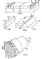
- FIG. 6 shows a transducer 23, in particular for an ultrasound compound scan.
- the ultrasound transducer elements 24a to 24n again form a now round but comb-shaped radiation or reception surface with group circuit 25.
- 26 is the connecting cable for the transducer.
- the rod design of Fig. 6 can be made by a mosaic or matrix design, e.g. by forming additional transverse gaps. The same naturally also applies to the array comb designs of FIGS. 1 to 5.
Landscapes
- Health & Medical Sciences (AREA)
- Life Sciences & Earth Sciences (AREA)
- Engineering & Computer Science (AREA)
- Biomedical Technology (AREA)
- Medical Informatics (AREA)
- Gynecology & Obstetrics (AREA)
- Biophysics (AREA)
- Nuclear Medicine, Radiotherapy & Molecular Imaging (AREA)
- Pathology (AREA)
- Radiology & Medical Imaging (AREA)
- Mechanical Engineering (AREA)
- Heart & Thoracic Surgery (AREA)
- Physics & Mathematics (AREA)
- Molecular Biology (AREA)
- Surgery (AREA)
- Animal Behavior & Ethology (AREA)
- General Health & Medical Sciences (AREA)
- Public Health (AREA)
- Veterinary Medicine (AREA)
- Ultra Sonic Daignosis Equipment (AREA)
- Investigating Or Analyzing Materials By The Use Of Ultrasonic Waves (AREA)
- Transducers For Ultrasonic Waves (AREA)
- Surgical Instruments (AREA)
Description
- Die Erfindung bezieht sich auf einen Ultraschallkopf gemäß den Merkmalen des Oberbegriffs des Patentanspruchs 1.
- Der Ultraschallkopf kann ein beliebig geformter Abtastkopf für B-Scan oder aber auch für A-Scan oder für ein ähnliches Abtastverfahren sein. Es kann sich im vorliegenden Fall also auch um einen Ultraschallkopf für z.B. Compound-Scan handeln. In besonderer Anwendung sollte der Schallkopf jedoch der Wandlerkamm eines Ultraschall-Arrays sein.
- Durch die US-PS 25 89 135 ist bereits ein Ultraschallkopf der eingangs genannten Art vorbekannt, der in Verbindung mit Sonarsystemen in Unterseebooten im Meereswasser eingesetzt wird. Bei diesem Ultraschallkopf beträgt die Höhe jedes einzelnen Wandlerelementes h = λ/4 (mit λ = Wellenlänge der abgestrahlten bzw. empfangenen Ultraschallwellen im Meereswasser). Die Breite b der einzelnen Wandiere!emente liegt nur geringfügig unter λ/4. Diese Größenverhältnisse zeigt zumindest die Querschnittsdarstellung der Figur 1 der US-PS. Ein solches Verhältnis zwischen Breite und Höhe, die sich in ihren Dimensionen nur geringfügig voneinander unterscheiden, führt zu einer relativ schlechten lateralen Auflösung.
- Dies gilt in diesem Sinne auch für einen Wandlerkamm, wie er beispielsweise durch den Artikel "Electronic sector scanning for ultrasonic diagnosis" von J. C. Somer aus der Zeitschrift ULTRASONICS, Juli 1968, Seiten 153 bis 159 bekannt ist. Im speziellen handelt es sich hierbei um ein sogenanntes phased-Array für Sektorabtastung. Die Breite jedes einzelnen Wandlerelementes ist geringfügig kleiner als die Hälfte der Wellenlänge der verwendeten Ultraschallschwingungen. Die Höhe beträgt etwa das 2,6 fache der Wandlerelementbreite. Wie die Praxis zeigt, lassen Wandlerelemente, die etwa λ/2 breit sind, hinsichtlich der Lateralauflösung immer noch zu wünschen übrig.
- Einen Vorschlag, wie bei Wandlerkämmen die Lateralauflösung verbessert werden kann, unterbreitet die nicht vorveröffentlichte US-PS 41 01 795. Gemäß deren Lehre ergibt sich eine verbesserte Lateralauflösung, wenn das Breite-Höhen-Verhältnis im Bereich von 0,4 bis 0,7 liegt. Wird z.B. für die Höhe des Wandlerelementes h = A/2 gewählt, so könnte nach der Lehre der US-PS 41 01 795 die Wandlerelementbreite zu b = etwa A/4 oder geringfügig kleiner als λ/4 gewählt werden. Bei einer derartigen Dimensionierung eines einzelnen Wandlerelementes sinkt jedoch die Abstrahl- bzw. Empfangsleistung mit zunehmender Feinteilung der Einzelelemente. D.h., wird ein Ultraschallkopf nach der Lehre der US-PS 41 01 795 mehr und mehr feingeteilt, so verbessert sich zwar die Lateralauflösung; gleichzeitig sinkt aber auch sehr rapide mit abnehmender Abstrahlfläche die Abstrahl- bzw. Empfangsleistung. Diesem nicht unerheblichen Nachteil versucht der Gegenstand der US-PS 41 01 795 dadurch entgegenzuwirken, daß der gesamte feingeteilte Wandlerkopf applikationsseitig mit einer besonderen doppelbödigen Anpassungsschicht versehen wird, die in der Zusammensetzung recht kompliziert aufgebaut ist.
- Aufgabe vorliegender Erfindung ist es, einen Ultraschallkopf der eingangs genannten Art aufzubauen, der in der Lateralauflösung erheblich verbessert ist und der dennoch gleichzeitig mit optimaler Abstrahl- bzw. Empfangsleistung für alle derzeit üblichen Abtastverfahren, also z.B. Compound-Scan, Linear-Array-Scan oder auch als phased-Array für Sektorscan, einsetzbar ist.
- Die Aufgabe wird erfindungsgemäß mit den Merkmalen des Kennzeichens des Patentanspruchs 1 gelöst.
- Eine entsprechend der Erfindung fein unterteilte Wandlereiementanordnung gewährleistet in der Gruppenzusammenschaltung trotz relativ hohen Teilungsverlustes (Zwischenräume mächen beispielsweise 2096 der aktiven Fläche aus) mindestens dieseibe Abstrahl- bzw. Empfangsleistung wie herkömmliche Wandlerelementanordnungen, wobei sich jedoch immer praktisch querschwingungsfreie Echoantwort ergibt. Die Lateralauflösung ist damit bei optimaler Abstrahl- bzw. Empfangsleistung ebenfalls optimal.
- Weitere Einzelheiten und Vorteile der Erfindung ergeben sich aus der nachfolgenden Beschreibung eines Ausführungsbeispiels anhand der Zeichnung in Verbindung mit den Unteransprüchen.
- Es zeigen:
- Figur 1 ein Ultraschall-Array mit herkömmlichem Wandlerkamm;
- Figur 2 ein Ultraschall-Array mit Wandlerkamm in Feinunterteilung gemäß der Erfindung;
- Figur 3 eine Unterteilungsform in trapezförmigen Schrägschritten über die Länge eines Wandlerstreifens;
- Figur 4 ein Einzelsegment der Unterteilung gemäß Fig. 3 in Vergrößerung;
- Figur 5 eine Unterteilungsform in trapezförmigen Schrägschritten über die Höhe des Wandlerelementstreifens;
- Figur 6 einen gemäß der Erfindung feinunterteilten Ultraschallkopf für Compound-Scan.
- Das Ultraschall-Array der Fig. 1 kann vom Prinzip her jenem des eingangs aufgeführten Somer-Artikels entsprechen. Es beinhaltet dann einen Wandlerkamm 1 mit einem Trägerteil 2, z.B. aus Epoxydharz. Der Wandlerkamm umfaßt eine Vielzahl von Wandlerelementen 3a bis 3n aus piezoelektrischem Material (z.B. aus Blei-Zirkonat-Titanat). Die einzelnen Wandlerelemente 3a bis 3n sind auf Abstand S nebeneinander am Trägerteil 2 angeordnet. Gemäß Somer-Artikel sind die Lücken 4 zwischen den einzelnen Wandlerelementen mit Abstandsstücken aus Epoxydharz ausgefüllt. Sie können selbstverständlich (z.B. gemäß Fig. 1) aber auch als Lücken unausgefüllt bleiben. Jedes einzelne Wandlerelement 3a bis 3n weist eine ihm zugeordnete Kontaktierung 5a bis 5n an der Oberseite und 6a bis 6n an der Unterseite (Silberbelege) für den Anschluß von Ansteuerleitungen 7a bis 7n bzw. 8a bis 8n auf. Die Anzahl der Wandlerelemente liegt z.B. im Bereich 125. Die Gesamtlänge des Ultraschall-Arrays ist mit L (ca. 10 cm) bezeichnet. Die Länge der einzelnen Wandlerelemente 3a bis 3n beträgt 1, ihre Höhe ist mit h angegeben und die Breite beträgt B. Die Spaltbreite der Lücken 4 besitzt den Wert S. Die Wandlerelementbreite B liegt im Bereich der Hälfte (A/2) der Wellenlänge der verwendeten Ultraschallschwingungen oder allenfalls geringfügig darunter. Die Höhe h ist gemäß den eingangsseitigen Voraussetzungen größer als die Breite B jedes einzelnen Wandlerelementes 3a bis 3n.
- Wie bereits erwähnt, ist die Lateralauflösung eines derartigen Ultraschall-Arrays, wie es z.B. in der Fig. 1 dargestellt ist, noch nicht optimal. Sie wird optimal bei mindestens gleicher Abstrahl- bzw. Empfangsleistung mit dem Ausführungsbeispiel der Fig. 2 (bzw. auch den Ausführungsbeispielen der Fig. 3 bis 6).
- Das Ultraschall-Array der Fig. 2 umfaßt wiederum einen Wandlerkamm 9, der an einem Träger 10 (z.B. wieder Epoxydharz) gehaltert ist. Im Gegensatz zum Wandlerkamm 1 des Arrays der Fig. 1 ist jedoch der Wandlerkamm 9 des Arrays der Fig. 2 feinunterteilt. Im dargestellten Ausführungsbeispiel der Fig. 2 befinden sich also anstelle eines einzigen Wandlerelementes 3a bis 3n gemäß der Fig. 1 nun zwei Einzelwandlerelemente 1 a, 12a bis 11 n, 12n. Die beiden Einzelelemente 11 a, 12a bis 11 n, 12n weisen jedes eine Breite b auf, die weniger als die Hälfte der Breite B eines Wandlerelementes 3a bis 3n des Arrays der Fig. 1 besitzt. Die Wandlerelementbreite b der Wandlerelemente 11 a, 12a und 11 n bis 12n in der Feinunterteilung des Ausführungsbeispieles der Fig. 2 ist also kleiner als λ/4 und dementsprechend auch wesentlich kleiner als die Hälfte (A/2) der Wellenlänge der verwendeten Ultraschallschwingungen. Von den Elementen 1 a, 12a bis 11 n, 12n der Feinunterteilung sind jedoch jeweils immer zwei benachbarte zu einer Gruppe 13 zusammengefaßt. Die gruppenweise Zusammenfassung erfolgt durch Lötstellen 14 an der Oberseite (Abstrahlfläche) und 16 an der Unterseite. Jede Gruppenkontaktierung weist einen eigenen Steuerleitungsanschluß 18 an der Oberfläche und 19 an der Unterseite auf. Innerhalb einer solchen Gruppe 13 ist dann die Summen-Abstrahl-/Empfangsfläche, die von jeweils zwei Wandlerelementen 11 a, 12a bis 11 n, 12n gemeinsam gebildet wird, einschließlich des vom Spalt 20 gebildeten Zwischenraumes etwa gleich groß der Aktivfläche eines einzelnen Wandlerelementes 3a bis 3n des Ultraschall-Arrays der Fig. 1. Trotz des relativ hohen Spaltverlustes (der Spaltverlust macht ca. 20 % der Aktivfläche aus) ergibt sich für jede der einzelnen Gruppen 13 des Wandlerkammes 9 mindestens dieselbe Abstrahl- bzw. Empfangsleistung wie für jedes der Wandlerelemente 3a bis 3n der Fig. 1, wobei jedoch die laterale Auflösung erheblich besser ist. Vergleicht man indes aktive Flächen, so ergibt sich beim Fein-Array der Fig. 2 sogar eine um etwa +4 dB höhere Echoantwort als beim herkömmlichen Array der Fig. 1.
- Bei einem Ausführungsbeispiel der Praxis umfaßt das Ultraschall-Array der Fig. 2 bei einer Ultraschallfrequenz von f = 2,25 MHz insgesamt 256 Einzelschwinger 11 a, 12a, bis 11 n, 12n. Die Breite b eines jeden Einzelschwingers beträgt etwa 0,26 mm. Die Höhe der Elemente beträgt etwa h = 0,7 mm und die Länge ungefähr I = 11 mm. Bei einer Spaltbreite in der Größenordnung von s = 0,05 bis 0,06 mm ergibt sich damit bei Zusammenfassung von insgesamt zwei Wandlerelementen zu einer Gruppe eine Gesamtgruppenbreite von etwa 0,57 mm, wobei die einzelnen Gruppen untereinander entlang dem Wandlerkamm 9 durch Spaltbreiten wiederum in der Größenordnung s = 0,05 bis 0,06 mm abgetrennt sind.
- Die Feinunterteilung des Wandlerkammes gemäß dem Array der Fig. 2 kann z.B. in Sägetechnik mittels Gattersäge oder auch mittels Schneidstrahl, z.B. Laser- oder Ultraschall-Schneidstrahl, vorgenommen werden. Ebensogut ist auch Anwendung von Stapeltechnik dünner Folien, LSI-Fotoresist- und Ätztechnik oder auch Sintertechnik in Stäbchenform möglich.
- Die Wandlerelemente 11 a, 12a bis 11 n, 12n, können die in Fig. 2 dargestellte Stäbchenform mit über die Wandlerlänge 1 und Wandlerhöhe h gleichbleibender Breite b haben. Ebensogut sind jedoch auch andere geometrische Formgebungen möglich, z.B. Trapezform nach Höhe h und/oder Länge 1, wobei jedoch die Breite b zumindest an einer Stelle des einzelnen Wandlerelementes den Bedingungen der Erfindung genügen sollte. Ausführungsbeispiele dieser Art zeigen die Fig. 3 bis 5 mit Wandlerelementformen 21 a bis 21 n oder 22a bis 22n.
- Das Ausführungsbeispiel der Fig. 2 arbeitet mit zwei Einzelelementen 11 a, 12a etc. bis 11 n, 12n pro Gruppe. Selbstverständlich können auch mehr als nur zwei, z.B. drei, vier oder mehr Einzelelemente, zu einer Wandlergruppe zusammengeschaltet werden. Die Einzelelemente können dann noch feiner unterteilt sein, so daß sich beispielsweise eine Breitenbedingung erheblich kleiner als A/4 und damit sehr viel kleiner als A/2 ergibt. Die Gesamtbreite jeder Wandlergruppe kann dann wieder etwa A/2 sein. Ein solches Ultraschall-Array eignet sich dann insbesondere wieder zur Anwendung für Sektor-Abtastung. Ebensogut kann jedoch auch die Gesamtbreite einer Wandlergruppe größer als A/2 sein. Derartige Ausbildungsformen finden Einsatz z.B. bei Linear-Arrays.
- Entsprechendes gilt auch für die Ausführungsform der Fig. 6, die einen Schallkopf 23 insbesondere für Ultraschall-Compound-Scan zeigt. Die Ultraschallwandlerelemente 24a bis 24n bilden wieder eine jetzt jedoch runde kammförmige Abstrahl- bzw. Empfangsfläche mit Gruppenschaltung 25. 26 ist dabei das Anschlußkabel für den Schallkopf. Die Stäbchenausführung der Fig. 6 kann bei Bedarf durch eine Mosaik- bzw. Matrix-Ausführung, z.B. durch Bildung zusätzlicher Querspalten, ersetzt werden. Dasselbe gilt selbstverständlich auch für die Array-Kamm-Ausführungen der Fig. 1 bis 5.
Claims (8)
Priority Applications (1)
| Application Number | Priority Date | Filing Date | Title |
|---|---|---|---|
| AT79102163T ATE3919T1 (de) | 1978-07-05 | 1979-06-28 | Ultraschallkopf. |
Applications Claiming Priority (2)
| Application Number | Priority Date | Filing Date | Title |
|---|---|---|---|
| DE2829570 | 1978-07-05 | ||
| DE2829570A DE2829570C2 (de) | 1978-07-05 | 1978-07-05 | Ultraschallkopf |
Publications (3)
| Publication Number | Publication Date |
|---|---|
| EP0006623A2 EP0006623A2 (de) | 1980-01-09 |
| EP0006623A3 EP0006623A3 (en) | 1980-08-20 |
| EP0006623B1 true EP0006623B1 (de) | 1983-06-22 |
Family
ID=6043626
Family Applications (1)
| Application Number | Title | Priority Date | Filing Date |
|---|---|---|---|
| EP79102163A Expired EP0006623B1 (de) | 1978-07-05 | 1979-06-28 | Ultraschallkopf |
Country Status (5)
| Country | Link |
|---|---|
| US (1) | US4305014A (de) |
| EP (1) | EP0006623B1 (de) |
| JP (1) | JPS5511696A (de) |
| AT (1) | ATE3919T1 (de) |
| DE (1) | DE2829570C2 (de) |
Families Citing this family (44)
| Publication number | Priority date | Publication date | Assignee | Title |
|---|---|---|---|---|
| DE2929541A1 (de) * | 1979-07-20 | 1981-02-05 | Siemens Ag | Ultraschallwandleranordnung |
| EP0040374A1 (de) * | 1980-05-21 | 1981-11-25 | Siemens Aktiengesellschaft | Ultraschallwandleranordnung und Verfahren zu seiner Herstellung |
| DE3019409A1 (de) * | 1980-05-21 | 1982-01-21 | Siemens AG, 1000 Berlin und 8000 München | Ultraschallwandleranordnung |
| DE3021449A1 (de) * | 1980-06-06 | 1981-12-24 | Siemens AG, 1000 Berlin und 8000 München | Ultraschallwandleranordnung und verfahren zu seiner herstellung |
| FR2485858B1 (fr) * | 1980-06-25 | 1986-04-11 | Commissariat Energie Atomique | Procede de fabrication de transducteurs ultrasonores de formes complexes et application a l'obtention de transducteurs annulaires |
| EP0043195A1 (de) * | 1980-06-26 | 1982-01-06 | United Kingdom Atomic Energy Authority | Ultraschallwandler |
| JPS5776031A (en) * | 1980-09-12 | 1982-05-12 | Int Harvester Co | Polyimide |
| US4398116A (en) * | 1981-04-30 | 1983-08-09 | Siemens Gammasonics, Inc. | Transducer for electronic focal scanning in an ultrasound imaging device |
| JPS58119299A (ja) * | 1982-01-07 | 1983-07-15 | Kureha Chem Ind Co Ltd | 走査型音波トランスジユ−サ−の製造法 |
| US4425525A (en) | 1982-02-16 | 1984-01-10 | General Electric Company | Ultrasonic transducer array shading |
| US4460841A (en) * | 1982-02-16 | 1984-07-17 | General Electric Company | Ultrasonic transducer shading |
| DE3207255C2 (de) * | 1982-03-01 | 1984-04-12 | Siemens AG, 1000 Berlin und 8000 München | Handgeführter Ultraschall-Applikator |
| DE3211733A1 (de) * | 1982-03-30 | 1983-10-06 | Siemens Ag | Ultraschall-applikator |
| DE3211734A1 (de) * | 1982-03-30 | 1983-10-06 | Siemens Ag | Ultraschall-applikator und verfahren zur herstellung desselben |
| DE3215529A1 (de) * | 1982-04-26 | 1983-10-27 | Siemens AG, 1000 Berlin und 8000 München | Ultraschall-applikator |
| US4523471A (en) * | 1982-09-28 | 1985-06-18 | Biosound, Inc. | Composite transducer structure |
| AU544464B2 (en) * | 1982-12-27 | 1985-05-30 | Tokyo Shibaura Denki Kabushiki Kaisha | Ultrasonic transducer |
| JPS605133A (ja) * | 1983-05-26 | 1985-01-11 | アドバンスト・テクノロジ−・ラボラトリ−ズ・インコ−ポレイテツド | 振動モ−ドを改良した超音波変換器 |
| FR2565033B1 (fr) * | 1984-05-22 | 1987-06-05 | Labo Electronique Physique | Dispositif de transduction ultrasonore a reseau d'elements transducteurs piezoelectriques |
| US4641291A (en) * | 1985-02-19 | 1987-02-03 | Ametek, Inc. | Phased array Doppler sonar transducer |
| FR2589247B1 (fr) * | 1985-10-25 | 1988-06-10 | Labo Electronique Physique | Appareil d'exploration de milieux par echographie ultrasonore comprenant un reseau d'elements transducteurs piezoelectiques |
| US4694699A (en) * | 1986-06-30 | 1987-09-22 | Universite De Sherbrooke | Acoustic microscopy |
| JPH028410U (de) * | 1988-06-30 | 1990-01-19 | ||
| NL8801776A (nl) * | 1988-07-13 | 1990-02-01 | Optische Ind De Oude Delft Nv | Ultrasone transducent omvattende tenminste een rij ultrasone elementen. |
| US4890268A (en) * | 1988-12-27 | 1989-12-26 | General Electric Company | Two-dimensional phased array of ultrasonic transducers |
| DE58906448D1 (de) * | 1989-02-22 | 1994-01-27 | Siemens Ag | Ultraschall-Array mit trapezförmigen Schwingerelementen sowie Verfahren und Vorrichtung zu seiner Herstellung. |
| DE59008863D1 (de) * | 1990-06-21 | 1995-05-11 | Siemens Ag | Verbund-Ultraschallwandler und Verfahren zur Herstellung eines strukturierten Bauelementes aus piezoelektrischer Keramik. |
| EP0509297A1 (de) * | 1991-04-16 | 1992-10-21 | Hewlett-Packard Company | Transoesophageale Ultraschallsonde |
| JPH06292669A (ja) * | 1991-04-17 | 1994-10-21 | Hewlett Packard Co <Hp> | 超音波プローブ |
| GB9109881D0 (en) * | 1991-05-08 | 1991-07-03 | Advanced Tech Lab | Transesophageal echocardiography scanner with rotating image plane |
| US5313834A (en) * | 1992-09-21 | 1994-05-24 | Airmar Technology Corporation | Phased array sonic transducers for marine instrument |
| US5398689A (en) * | 1993-06-16 | 1995-03-21 | Hewlett-Packard Company | Ultrasonic probe assembly and cable therefor |
| US5592730A (en) * | 1994-07-29 | 1997-01-14 | Hewlett-Packard Company | Method for fabricating a Z-axis conductive backing layer for acoustic transducers using etched leadframes |
| US5550792A (en) * | 1994-09-30 | 1996-08-27 | Edo Western Corp. | Sliced phased array doppler sonar system |
| DE19833213C2 (de) * | 1998-07-23 | 2002-11-07 | Siemens Ag | Ultraschall-Sendeanordnung |
| JP5067821B2 (ja) * | 2001-04-13 | 2012-11-07 | 古野電気株式会社 | 多周波送受波器 |
| HU224572B1 (hu) | 2002-11-05 | 2005-11-28 | Khaled Awad Saleh Nashwan | Készülék érrendszeri megbetegedésben szenvedők infra-, hallható- és ultrahang hullámok kombinációjával való kezelésére |
| US20060100522A1 (en) * | 2004-11-08 | 2006-05-11 | Scimed Life Systems, Inc. | Piezocomposite transducers |
| US7302744B1 (en) * | 2005-02-18 | 2007-12-04 | The United States Of America Represented By The Secretary Of The Navy | Method of fabricating an acoustic transducer array |
| US8615284B2 (en) * | 2006-09-06 | 2013-12-24 | Innurvation, Inc. | Method for acoustic information exchange involving an ingestible low power capsule |
| RU2330389C2 (ru) * | 2006-09-21 | 2008-07-27 | Федеральное Государственное Образовательное Учреждение Высшего Профессионального Образования "Южный Федеральный Университет" | Пьезоэлектрический электромеханический преобразователь |
| RU2335038C1 (ru) * | 2007-04-26 | 2008-09-27 | Закрытое акционерное общество научно-исследовательский институт интроскопии Московского научно-производственного объединения "СПЕКТР" (ЗАО НИИИН МНПО "СПЕКТР") | Ультразвуковая антенная решетка |
| US9224938B2 (en) | 2011-04-11 | 2015-12-29 | Halliburton Energy Services, Inc. | Piezoelectric element and method to remove extraneous vibration modes |
| WO2021210151A1 (ja) * | 2020-04-17 | 2021-10-21 | 本多電子株式会社 | ソナー |
Family Cites Families (13)
| Publication number | Priority date | Publication date | Assignee | Title |
|---|---|---|---|---|
| US2408028A (en) * | 1934-01-19 | 1946-09-24 | Submarine Signal Co | Means for sending and receiving compressional waves |
| DE732890C (de) | 1938-03-13 | 1954-08-23 | Electroacustic Gmbh | Verfahren zum Abstrahlen grosser Wellenenergie unter grossem Winkel |
| US2589135A (en) * | 1947-04-25 | 1952-03-11 | Bell Telephone Labor Inc | Submarine signaling device |
| US2956184A (en) * | 1954-11-01 | 1960-10-11 | Honeywell Regulator Co | Transducer |
| US3036231A (en) * | 1958-07-24 | 1962-05-22 | Sperry Prod Inc | High resolution piezoelectric transducer |
| US3718898A (en) * | 1971-12-13 | 1973-02-27 | Us Navy | Transducer |
| DE2308443A1 (de) * | 1972-02-22 | 1973-08-30 | Univ Erasmus | Untersuchungsgeraet mit katheter zum untersuchen eines hohlen organes mit hilfe von ultraschallwellen und verfahren zum herstellen des katheters |
| US3971962A (en) * | 1972-09-21 | 1976-07-27 | Stanford Research Institute | Linear transducer array for ultrasonic image conversion |
| US3924259A (en) | 1974-05-15 | 1975-12-02 | Raytheon Co | Array of multicellular transducers |
| US4122725A (en) * | 1976-06-16 | 1978-10-31 | The United States Of America As Represented By The Administrator Of The National Aeronautics And Space Administration | Length mode piezoelectric ultrasonic transducer for inspection of solid objects |
| JPS5353393A (en) * | 1976-10-25 | 1978-05-15 | Matsushita Electric Ind Co Ltd | Ultrasonic probe |
| US4156158A (en) * | 1977-08-17 | 1979-05-22 | Westinghouse Electric Corp. | Double serrated piezoelectric transducer |
| DE2829581C2 (de) * | 1978-07-05 | 1980-01-17 | Siemens Ag, 1000 Berlin Und 8000 Muenchen | Verfahren zur Herstellung von Ultraschallköpfen |
-
1978
- 1978-07-05 DE DE2829570A patent/DE2829570C2/de not_active Expired
-
1979
- 1979-06-19 US US06/049,898 patent/US4305014A/en not_active Expired - Lifetime
- 1979-06-28 AT AT79102163T patent/ATE3919T1/de not_active IP Right Cessation
- 1979-06-28 EP EP79102163A patent/EP0006623B1/de not_active Expired
- 1979-07-05 JP JP8548579A patent/JPS5511696A/ja active Pending
Also Published As
| Publication number | Publication date |
|---|---|
| ATE3919T1 (de) | 1983-07-15 |
| JPS5511696A (en) | 1980-01-26 |
| EP0006623A2 (de) | 1980-01-09 |
| DE2829570B1 (de) | 1979-04-26 |
| US4305014A (en) | 1981-12-08 |
| DE2829570C2 (de) | 1979-12-20 |
| EP0006623A3 (en) | 1980-08-20 |
Similar Documents
| Publication | Publication Date | Title |
|---|---|---|
| EP0006623B1 (de) | Ultraschallkopf | |
| DE68924057T2 (de) | Anordnung von Ultraschallwandlern. | |
| DE3214789C2 (de) | ||
| DE69120735T2 (de) | Fester Ursprung eines zweiflächigen Ultraschallwandlers | |
| DE3304667C2 (de) | Ultraschall-Anordnung und Verfahren zu ihrer Herstellung | |
| DE3650004T2 (de) | Ultraschallsonde. | |
| EP0025092B1 (de) | Ultraschallwandleranordnung und Verfahren zu ihrer Herstellung | |
| EP0041664B1 (de) | Verfahren zur Herstellung einer Ultraschallwandleranordnung | |
| DE2829539C2 (de) | Verfahren zur Herstellung von Ultraschallköpfen | |
| DE2853857C3 (de) | Ultraschall-Ortungseinrichtung | |
| DE10155894A1 (de) | Piezoelektrische Mehrschichtstruktur mit gleichmässigem elektrischem Feld | |
| DE3733776A1 (de) | Ultraschallsonde | |
| DE3526488A1 (de) | Ultraschall-wandler mit piezoelektrischem verbundmaterial | |
| DE1270197B (de) | Verzoegerungsanordnung mit Dispersion fuer akustische Wellen | |
| DE2855143C2 (de) | Verfahren zur Herstellung eines Ultraschallwandlers und entsprechend hergestellter Wandler | |
| DE10341730A1 (de) | Mehrfachmuster-Transducerarray und Verfahren zu deren Verwendung | |
| DE602004010097T2 (de) | Piezoelektrische kompositmaterialien und herstellungsverfahren dafür | |
| EP4107543B1 (de) | Wasserschallwandler | |
| DE2533572C3 (de) | Anordnung zur Erzeugung eines Schwerpunktsignals aus einer Reihe von Videosignalen | |
| DE2829581C2 (de) | Verfahren zur Herstellung von Ultraschallköpfen | |
| DE69524817T2 (de) | Diagnoseultraschallwandleranordnung mit Elevationsfokus | |
| DE2829612C2 (de) | Verfahren zur Herstellung von Ultraschallköpfen | |
| DE102008049788A1 (de) | Ultraschallwandler mit mindestens einem vollaktiven, monolithischen Piezoelement, Verfahren zum selektiven Kontaktieren von Innenelektroden des Ultraschallwandlers durch Abtrag von Elektrodenmaterial und Verwendung des Utraschallwandlers | |
| DE102008049541A1 (de) | Ultraschallwandler mit mindestens einem vollaktiven, monolithischen Piezoelement, Verfahren zum Kontaktieren des Ultraschallwandlers mittels photostrukturierter Isolationsschicht und Verwendung des Ultraschallwandlers | |
| DE2829569C2 (de) | Verfahren zur Herstellung von Ultraschallköpfen |
Legal Events
| Date | Code | Title | Description |
|---|---|---|---|
| PUAI | Public reference made under article 153(3) epc to a published international application that has entered the european phase |
Free format text: ORIGINAL CODE: 0009012 |
|
| AK | Designated contracting states |
Designated state(s): AT CH FR GB NL |
|
| PUAL | Search report despatched |
Free format text: ORIGINAL CODE: 0009013 |
|
| AK | Designated contracting states |
Designated state(s): AT CH FR GB NL |
|
| 17P | Request for examination filed | ||
| GRAA | (expected) grant |
Free format text: ORIGINAL CODE: 0009210 |
|
| PGFP | Annual fee paid to national office [announced via postgrant information from national office to epo] |
Ref country code: FR Payment date: 19830607 Year of fee payment: 5 |
|
| AK | Designated contracting states |
Designated state(s): AT CH FR GB NL |
|
| REF | Corresponds to: |
Ref document number: 3919 Country of ref document: AT Date of ref document: 19830715 Kind code of ref document: T |
|
| PGFP | Annual fee paid to national office [announced via postgrant information from national office to epo] |
Ref country code: NL Payment date: 19830630 Year of fee payment: 5 |
|
| PGFP | Annual fee paid to national office [announced via postgrant information from national office to epo] |
Ref country code: AT Payment date: 19830804 Year of fee payment: 5 |
|
| PGFP | Annual fee paid to national office [announced via postgrant information from national office to epo] |
Ref country code: CH Payment date: 19830824 Year of fee payment: 5 |
|
| ET | Fr: translation filed | ||
| PLBE | No opposition filed within time limit |
Free format text: ORIGINAL CODE: 0009261 |
|
| STAA | Information on the status of an ep patent application or granted ep patent |
Free format text: STATUS: NO OPPOSITION FILED WITHIN TIME LIMIT |
|
| PG25 | Lapsed in a contracting state [announced via postgrant information from national office to epo] |
Ref country code: AT Effective date: 19840628 |
|
| PG25 | Lapsed in a contracting state [announced via postgrant information from national office to epo] |
Ref country code: CH Effective date: 19840630 |
|
| 26N | No opposition filed | ||
| PG25 | Lapsed in a contracting state [announced via postgrant information from national office to epo] |
Ref country code: NL Effective date: 19850101 |
|
| GBPC | Gb: european patent ceased through non-payment of renewal fee | ||
| NLV4 | Nl: lapsed or anulled due to non-payment of the annual fee | ||
| PG25 | Lapsed in a contracting state [announced via postgrant information from national office to epo] |
Ref country code: FR Free format text: LAPSE BECAUSE OF NON-PAYMENT OF DUE FEES Effective date: 19850228 |
|
| REG | Reference to a national code |
Ref country code: CH Ref legal event code: PL |
|
| REG | Reference to a national code |
Ref country code: FR Ref legal event code: ST |
|
| PG25 | Lapsed in a contracting state [announced via postgrant information from national office to epo] |
Ref country code: GB Effective date: 19881118 |