EP0004282A2 - Lit pour malades - Google Patents
Lit pour malades Download PDFInfo
- Publication number
- EP0004282A2 EP0004282A2 EP79100471A EP79100471A EP0004282A2 EP 0004282 A2 EP0004282 A2 EP 0004282A2 EP 79100471 A EP79100471 A EP 79100471A EP 79100471 A EP79100471 A EP 79100471A EP 0004282 A2 EP0004282 A2 EP 0004282A2
- Authority
- EP
- European Patent Office
- Prior art keywords
- backrest
- telescopic
- sick bed
- lower leg
- bed according
- Prior art date
- Legal status (The legal status is an assumption and is not a legal conclusion. Google has not performed a legal analysis and makes no representation as to the accuracy of the status listed.)
- Granted
Links
Images


Classifications
-
- A—HUMAN NECESSITIES
- A61—MEDICAL OR VETERINARY SCIENCE; HYGIENE
- A61G—TRANSPORT, PERSONAL CONVEYANCES, OR ACCOMMODATION SPECIALLY ADAPTED FOR PATIENTS OR DISABLED PERSONS; OPERATING TABLES OR CHAIRS; CHAIRS FOR DENTISTRY; FUNERAL DEVICES
- A61G7/00—Beds specially adapted for nursing; Devices for lifting patients or disabled persons
- A61G7/002—Beds specially adapted for nursing; Devices for lifting patients or disabled persons having adjustable mattress frame
- A61G7/015—Beds specially adapted for nursing; Devices for lifting patients or disabled persons having adjustable mattress frame divided into different adjustable sections, e.g. for Gatch position
Definitions
- the invention relates to a hospital bed with a lying surface consisting of a backrest, a middle part and a lower leg rest, with axes of rotation lying in a horizontal plane for the backrest and for the lower leg rest and articulated axes between the backrest and the middle part and the middle part and the lower leg rest lie and move in the space between the axes of rotation and with two telescopic supports which are articulated at one end to the middle part and at the other end to the backrest or lower leg rest and can be actuated via a handle.
- the lower leg rest and the back rest can only be adjusted independently of one another.
- a transport chair in which the lying surface is formed from a lower leg rest, a middle part and a back rest.
- the middle section which is attached to the chassis equipped with floor rolls, maintains its position with all adjustment movements.
- To the The lower leg and the backrest are pivotally articulated and connected via a coupling rod.
- the coupling rod ensures that when the backrest is raised, the lower leg rest is simultaneously lowered. If the backrest is pivoted from the vertical position towards an inclined position, the lower legrest is pivoted upwards. An adjustment movement of the middle part or an adjustment of the backrest or the lower leg rest alone are not possible with the known transport chair.
- the invention has for its object to design a patient bed of the type mentioned so that either the lower leg rest with the backrest synchronously in opposite directions of rotation or the lower leg rest and the backrest are independently adjustable.
- the device for locking the linkage parts of the telescopic linkage and the coupling means for the actuating devices of the telescopic supports can be actuated synchronously via a Bowden cable, which can be brought into its switching positions via a handle.
- the sick bed shown in FIGS. 1 to 4 has a backrest 1, a middle part 2 and a lower leg rest 3, which form the lying surface of the sick bed.
- the backrest 1 is pivotably articulated in an articulated axis 4 and the lower leg rest 3 in an articulated axis 5 on the central part 2.
- the backrest 1 is rotatably supported about an axis 6 and the lower leg rest 3 about an axis 7 in the frame of the hospital bed.
- the hinge axes 4 and 5 are in the space between see the axes of rotation 6 and 7 and also move in the different positions of the backrest, middle section and lower leg rest in this room.
- This arrangement of the hinge axes 4.5 between the backrest 1 and the middle part 2 or the lower leg rest 3 and the middle part 2 with respect to the fixed axes of rotation 6 and 7 makes it possible for the patient to support the adjustment movements of the lying surface parts with his body weight.
- the adjustment device of the hospital bed has two telescopic supports 8, 9, which are articulated with their outer tubes 10, 11 at the rear end to brackets 12 which are fastened to the middle part 2 in the region of their flanges 13.
- the extendable tube 14 of the telescopic support 8 is articulated on a bracket 15 which is fixed to the backrest 1 with its fastening flange 16.
- the extendable tube 17 of the telescopic support 9 is articulated on a bracket 18 which is fixed to the lower leg rest 3 with its fastening flange 19.
- energy stores e.g. uncontrolled or controlled gas springs can be provided, by means of which the weights of the lying surface parts to be adjusted are compensated.
- the actuating device for the telescopic supports 8, 9 has handles 20 which are connected to one another via a shaft 21 which is rotatably mounted in the frame of the hospital bed. From Fig. 2 it follows that the handles 20 can be actuated from both sides of the bed.
- a lever 22 is attached to the shaft 21, which carries a pin 23 which engages in an elongated hole 24 of a rod 25 which leads to the actuating lever 26 of a blocking device 27 of the telescopic support 8.
- the blocking device 27 has one Locking bolt 28, which is guided in a housing 29 which is attached to the outer tube 10 of the telescopic support 8.
- the bolt is fixed via a cross pin 30 to the upper part 31 of the housing, which has an inclined surface 32 which extends at the same angle as an inclined surface 33 of the housing.
- the locking bolt 28 has a collar 34 on which a cylindrical helical spring 35 is supported.
- the locking end 36 of the locking bolt engages in a locking recess 37 of the extendable tube 14.
- the extendable tube 14 is provided with a series of locking recesses 37.
- Fig. 4 it follows that the pin 23 is coupled to a rod 38 which runs parallel to the rod 25 and leads to an actuating lever 39 of a blocking device 40, which is constructed in the same sense as the blocking device 27.
- a blocking device 40 which is constructed in the same sense as the blocking device 27.
- At the end of the rod 38 there is an elongated hole 41 through which an idle stroke is achieved in relation to the actuating lever 39, provided the shaft 21 and the lever 22 are rotated counterclockwise in FIG. 3. In this case, the blocking device 27 is brought into its unlocked position.
- the blocking device 40 is brought into the unlocked position via the rod 38, while the pin 23 is in the slot 24 makes an idle stroke so that the blocking device 27 is not actuated. In this case, the blocking device 40 releases the extendable tube 17 of the telescopic support 9, so that the lower leg rest 3 can be adjusted.
- a telescopic linkage 42 is arranged between the actuating levers 26 and 39 of the blocking devices 27 and 40.
- a spring 44 is provided which is supported at one end on the extendable rod 45.
- the extendable rod 45 is articulated on the actuating lever 26 of the blocking device 27.
- the extendable rod 45 can be fixed relative to the outer tube via a locking device 46. If the telescopic linkage 42 is locked and forms a coupling rod between the actuating levers 26 and 39, the blocking devices 27 and 40 are brought into an unlocked position when the handle 20 is actuated, so that the backrest and the lower part leg rest can be adjusted at the same time.
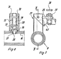
- a telescopic linkage 47 is arranged between the backrest 1 and the lower leg rest 3.
- the outer tube 48 is designed as a flat rectangular tube and is articulated on the bracket 18 via a bracket 49.
- a locking device 50 is fastened to the outer tube 48 and is constructed in the same way as the blocking devices. It has a housing 51 with an inclined surface 52 with which the inclined surface of an upper part 53 interacts.
- a locking bolt is fastened to the upper part, which is slidably mounted in the housing 51 and is loaded with a spring. The locking bolt engages in a locking recess 54 of an extendable part 55.
- the extendable part 55 is articulated on a bracket 15 of the backrest 1.
- a handle 56 is fastened to the upper part 53 and must be brought into the position shown in solid lines in FIG. 3 in order to initiate the locking of the parts 48 and 55 of the telescopic linkage.
- the locking device 50 for the telescopic linkage only snaps between the backrest and the lower leg rest when the backrest has assumed an inclined position of approximately 30 °. Only from this point in time is the lower leg rest 3 lowered when the backrest 1 is raised further.
- a Bowden cable 57 is provided, via which g nges 47 at the time of locking of the telescopic linkage Locking of the telescopic linkage 42 is made so that only the handle 56 needs to be actuated when switching to simultaneous actuation of the backrest 1 and the lower leg rest 3.
- the handle 56 is shown in FIG. 3 in dash-dotted lines in the position in which the locking devices of the telescopic linkage are released.
- the handle 56 is equipped with a stop arm 58 which cooperates with the front edge of the tab 12.
- the stop arm 58 works together with the bracket 12, so that the handle 56 is pivoted into the unlocked position.
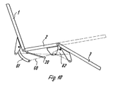
- the telescopic linkage 60 provided between the backrest 1 and the lower leg rest 3 assumes an acute angle in the horizontal position of the lying surface parts with respect to the lying surface.
- an arcuate arm 61 is attached, which projects with its free end into the area below the middle part 2 and to which the extendable part 62 of the telescopic linkage 60 is articulated.
- a bracket 63 is attached to the lower leg rest 3, to which the outer tube 64 of the telescopic linkage is articulated.
- the telescopic linkage is assigned a locking device 65, which is coupled via a Bowden cable 57 to the locking device 46 of the telescopic linkage 42 of the actuating device for the telescopic supports 8 and 9.
- the locking devices 65 and 46 can already be switched on in the horizontal position of the lying surface parts. During the entire adjustment movements of the backrest 1 and the lower leg rest 2, the locking devices 27 and 40 assigned to the telescopic supports 8, 9 are in the released position.
- the arrangement of the telescopic linkage 60 shown in FIGS. 8 to 10 ensures that when the backrest 1 is pivoted out of the horizontal position, the lower leg rest 3 initially does not move visibly. Only after a certain adjustment angle of the backrest 1 is the lower leg rest 3 pivoted more intensely.
- the lying surface parts 1, 2, 3 assume a sitting position for the patient.
- This illustration also shows that the middle part 2 has been moved into an inclined position.
Landscapes
- Health & Medical Sciences (AREA)
- Nursing (AREA)
- Life Sciences & Earth Sciences (AREA)
- Animal Behavior & Ethology (AREA)
- General Health & Medical Sciences (AREA)
- Public Health (AREA)
- Veterinary Medicine (AREA)
- Invalid Beds And Related Equipment (AREA)
- Accommodation For Nursing Or Treatment Tables (AREA)
Applications Claiming Priority (2)
| Application Number | Priority Date | Filing Date | Title |
|---|---|---|---|
| DE2811409 | 1978-03-16 | ||
| DE19782811409 DE2811409C2 (de) | 1978-03-16 | 1978-03-16 | Krankenbett |
Publications (3)
| Publication Number | Publication Date |
|---|---|
| EP0004282A2 true EP0004282A2 (fr) | 1979-10-03 |
| EP0004282A3 EP0004282A3 (en) | 1979-10-31 |
| EP0004282B1 EP0004282B1 (fr) | 1981-03-04 |
Family
ID=6034597
Family Applications (1)
| Application Number | Title | Priority Date | Filing Date |
|---|---|---|---|
| EP19790100471 Expired EP0004282B1 (fr) | 1978-03-16 | 1979-02-19 | Lit pour malades |
Country Status (4)
| Country | Link |
|---|---|
| EP (1) | EP0004282B1 (fr) |
| AT (1) | AT365921B (fr) |
| DE (1) | DE2811409C2 (fr) |
| ES (1) | ES242039Y (fr) |
Families Citing this family (5)
| Publication number | Priority date | Publication date | Assignee | Title |
|---|---|---|---|---|
| DE2913712C2 (de) * | 1979-04-05 | 1987-12-23 | Joh. Stiegelmeyer & Co Gmbh, 4900 Herford | Krankenbett |
| DE2943546C2 (de) * | 1979-10-27 | 1985-04-25 | L. & C. Arnold Gmbh, 7060 Schorndorf | Krankenbett |
| DE3703433C3 (de) * | 1987-02-05 | 1996-08-08 | Wissner Bosserhoff Gmbh | Krankenbett mit motorisch oder mechanisch neigbarem Rückenrahmen |
| US5105486A (en) * | 1990-06-18 | 1992-04-21 | Joerns Healthcare Inc. | Adjustable bed |
| DE19544250C1 (de) * | 1995-11-28 | 1997-05-28 | Stiegelmeyer & Co Gmbh | Kranken- oder Pflegebett mit einer mehrteiligen Liegefläche |
Citations (6)
| Publication number | Priority date | Publication date | Assignee | Title |
|---|---|---|---|---|
| DE192249C (fr) * | ||||
| DE540623C (de) * | 1928-07-19 | 1932-01-09 | Everitt S Patents Company Ltd | Einstellbares Bettgestell |
| DE662465C (de) * | 1935-10-09 | 1938-07-14 | John Eriksen | Matratze, insbesondere fuer Krankenbetten |
| US2620489A (en) * | 1946-07-13 | 1952-12-09 | Luther E Holm | Hospital bed adjusting mechanism |
| US3127619A (en) * | 1958-06-02 | 1964-04-07 | United States Bedding Co | Contour bed |
| DE2311607A1 (de) * | 1973-03-09 | 1974-09-19 | Bremshey Ag | Bett, insbesondere krankenbett |
-
1978
- 1978-03-16 DE DE19782811409 patent/DE2811409C2/de not_active Expired
-
1979
- 1979-02-19 EP EP19790100471 patent/EP0004282B1/fr not_active Expired
- 1979-02-22 AT AT138779A patent/AT365921B/de not_active IP Right Cessation
- 1979-03-14 ES ES1979242039U patent/ES242039Y/es not_active Expired
Patent Citations (6)
| Publication number | Priority date | Publication date | Assignee | Title |
|---|---|---|---|---|
| DE192249C (fr) * | ||||
| DE540623C (de) * | 1928-07-19 | 1932-01-09 | Everitt S Patents Company Ltd | Einstellbares Bettgestell |
| DE662465C (de) * | 1935-10-09 | 1938-07-14 | John Eriksen | Matratze, insbesondere fuer Krankenbetten |
| US2620489A (en) * | 1946-07-13 | 1952-12-09 | Luther E Holm | Hospital bed adjusting mechanism |
| US3127619A (en) * | 1958-06-02 | 1964-04-07 | United States Bedding Co | Contour bed |
| DE2311607A1 (de) * | 1973-03-09 | 1974-09-19 | Bremshey Ag | Bett, insbesondere krankenbett |
Also Published As
| Publication number | Publication date |
|---|---|
| DE2811409C2 (de) | 1982-04-15 |
| ATA138779A (de) | 1981-07-15 |
| ES242039U (es) | 1979-07-01 |
| ES242039Y (es) | 1979-12-01 |
| DE2811409A1 (de) | 1979-09-20 |
| EP0004282B1 (fr) | 1981-03-04 |
| AT365921B (de) | 1982-02-25 |
| EP0004282A3 (en) | 1979-10-31 |
Similar Documents
| Publication | Publication Date | Title |
|---|---|---|
| EP0159562B1 (fr) | Fauteuil élévateur | |
| DE3031435A1 (de) | Durch schwenken verstellbarer stuhl | |
| DE1283458B (de) | Sessel mit einer ein- und ausfahrbaren Beinstuetze | |
| EP0172528B1 (fr) | Cadre d'attelage avec au moins un crochet | |
| DE3309174C1 (de) | Bettseitenteil | |
| EP0098414B1 (fr) | Dispositif de réglage en hauteur pour sièges de véhicules | |
| DE1529675B1 (de) | Senkrecht einstellbarer Bett-Tisch | |
| DE1162981B (de) | Hebelverstellgetriebe fuer Sitz-Liegesessel mit ausschwenkbarer Beinstuetze | |
| DE2102911B2 (de) | Maehwerk | |
| EP0004282B1 (fr) | Lit pour malades | |
| DE2913712C2 (de) | Krankenbett | |
| DE4236195C2 (de) | Kranken- oder Pflegebett | |
| DE3249163C2 (fr) | ||
| DE3322017C2 (fr) | ||
| EP0399618A1 (fr) | Lit | |
| EP1284710B1 (fr) | Siege pour accouchement | |
| DE7807972U1 (de) | Krankenbett | |
| EP0088957B1 (fr) | Fauteuil de soins dentaires | |
| EP0553418B1 (fr) | Table avec plateau basculant et réglable en hauteur | |
| DE2318815C2 (de) | Hochklappbares Liegemöbel mit Tisch | |
| DE2640895B2 (de) | Schlafliege für das Fahrerhaus eines Kraftfahrzeuges | |
| EP3530552B1 (fr) | Cabine de conducteur | |
| DE4242507C2 (de) | Krankenbett | |
| DE2028417C3 (de) | Wägevorrichtung für Betten | |
| DE2000778A1 (de) | Krankenbett mit gegenueber einem Untergestell waagerecht hoehenverstellbarem und unabhaengig hiervon um seine Querachse neigbarem Matrazenrahmen |
Legal Events
| Date | Code | Title | Description |
|---|---|---|---|
| PUAI | Public reference made under article 153(3) epc to a published international application that has entered the european phase |
Free format text: ORIGINAL CODE: 0009012 |
|
| PUAL | Search report despatched |
Free format text: ORIGINAL CODE: 0009013 |
|
| AK | Designated contracting states |
Designated state(s): BE CH FR IT LU NL |
|
| AK | Designated contracting states |
Designated state(s): BE CH FR IT LU NL |
|
| 17P | Request for examination filed | ||
| ITF | It: translation for a ep patent filed |
Owner name: STUDIO INGG. FISCHETTI & WEBER |
|
| GRAA | (expected) grant |
Free format text: ORIGINAL CODE: 0009210 |
|
| AK | Designated contracting states |
Designated state(s): BE CH FR IT LU NL |
|
| PLBI | Opposition filed |
Free format text: ORIGINAL CODE: 0009260 |
|
| PGFP | Annual fee paid to national office [announced via postgrant information from national office to epo] |
Ref country code: FR Payment date: 19820120 Year of fee payment: 4 |
|
| 26 | Opposition filed |
Opponent name: L. & C. ARNOLD GMBH Effective date: 19811129 |
|
| PGFP | Annual fee paid to national office [announced via postgrant information from national office to epo] |
Ref country code: LU Payment date: 19820217 Year of fee payment: 4 |
|
| PG25 | Lapsed in a contracting state [announced via postgrant information from national office to epo] |
Ref country code: LU Free format text: LAPSE BECAUSE OF NON-PAYMENT OF DUE FEES Effective date: 19820228 |
|
| PGFP | Annual fee paid to national office [announced via postgrant information from national office to epo] |
Ref country code: NL Payment date: 19820228 Year of fee payment: 4 |
|
| PGFP | Annual fee paid to national office [announced via postgrant information from national office to epo] |
Ref country code: CH Payment date: 19820331 Year of fee payment: 4 Ref country code: BE Payment date: 19820331 Year of fee payment: 4 |
|
| PG25 | Lapsed in a contracting state [announced via postgrant information from national office to epo] |
Ref country code: BE Effective date: 19830219 |
|
| PG25 | Lapsed in a contracting state [announced via postgrant information from national office to epo] |
Ref country code: CH Effective date: 19830228 |
|
| PG25 | Lapsed in a contracting state [announced via postgrant information from national office to epo] |
Ref country code: NL Effective date: 19830901 |
|
| NLV4 | Nl: lapsed or anulled due to non-payment of the annual fee | ||
| PG25 | Lapsed in a contracting state [announced via postgrant information from national office to epo] |
Ref country code: FR Free format text: LAPSE BECAUSE OF NON-PAYMENT OF DUE FEES Effective date: 19831031 |
|
| REG | Reference to a national code |
Ref country code: CH Ref legal event code: PL |
|
| REG | Reference to a national code |
Ref country code: FR Ref legal event code: ST |
|
| PLBN | Opposition rejected |
Free format text: ORIGINAL CODE: 0009273 |
|
| STAA | Information on the status of an ep patent application or granted ep patent |
Free format text: STATUS: OPPOSITION REJECTED |
|
| 27O | Opposition rejected |
Effective date: 19840606 |