EP0004282A2 - Hospital bed - Google Patents
Hospital bed Download PDFInfo
- Publication number
- EP0004282A2 EP0004282A2 EP79100471A EP79100471A EP0004282A2 EP 0004282 A2 EP0004282 A2 EP 0004282A2 EP 79100471 A EP79100471 A EP 79100471A EP 79100471 A EP79100471 A EP 79100471A EP 0004282 A2 EP0004282 A2 EP 0004282A2
- Authority
- EP
- European Patent Office
- Prior art keywords
- backrest
- telescopic
- sick bed
- lower leg
- bed according
- Prior art date
- Legal status (The legal status is an assumption and is not a legal conclusion. Google has not performed a legal analysis and makes no representation as to the accuracy of the status listed.)
- Granted
Links
Images


Classifications
-
- A—HUMAN NECESSITIES
- A61—MEDICAL OR VETERINARY SCIENCE; HYGIENE
- A61G—TRANSPORT, PERSONAL CONVEYANCES, OR ACCOMMODATION SPECIALLY ADAPTED FOR PATIENTS OR DISABLED PERSONS; OPERATING TABLES OR CHAIRS; CHAIRS FOR DENTISTRY; FUNERAL DEVICES
- A61G7/00—Beds specially adapted for nursing; Devices for lifting patients or disabled persons
- A61G7/002—Beds specially adapted for nursing; Devices for lifting patients or disabled persons having adjustable mattress frame
- A61G7/015—Beds specially adapted for nursing; Devices for lifting patients or disabled persons having adjustable mattress frame divided into different adjustable sections, e.g. for Gatch position
Definitions
- the invention relates to a hospital bed with a lying surface consisting of a backrest, a middle part and a lower leg rest, with axes of rotation lying in a horizontal plane for the backrest and for the lower leg rest and articulated axes between the backrest and the middle part and the middle part and the lower leg rest lie and move in the space between the axes of rotation and with two telescopic supports which are articulated at one end to the middle part and at the other end to the backrest or lower leg rest and can be actuated via a handle.
- the lower leg rest and the back rest can only be adjusted independently of one another.
- a transport chair in which the lying surface is formed from a lower leg rest, a middle part and a back rest.
- the middle section which is attached to the chassis equipped with floor rolls, maintains its position with all adjustment movements.
- To the The lower leg and the backrest are pivotally articulated and connected via a coupling rod.
- the coupling rod ensures that when the backrest is raised, the lower leg rest is simultaneously lowered. If the backrest is pivoted from the vertical position towards an inclined position, the lower legrest is pivoted upwards. An adjustment movement of the middle part or an adjustment of the backrest or the lower leg rest alone are not possible with the known transport chair.
- the invention has for its object to design a patient bed of the type mentioned so that either the lower leg rest with the backrest synchronously in opposite directions of rotation or the lower leg rest and the backrest are independently adjustable.
- the device for locking the linkage parts of the telescopic linkage and the coupling means for the actuating devices of the telescopic supports can be actuated synchronously via a Bowden cable, which can be brought into its switching positions via a handle.
- the sick bed shown in FIGS. 1 to 4 has a backrest 1, a middle part 2 and a lower leg rest 3, which form the lying surface of the sick bed.
- the backrest 1 is pivotably articulated in an articulated axis 4 and the lower leg rest 3 in an articulated axis 5 on the central part 2.
- the backrest 1 is rotatably supported about an axis 6 and the lower leg rest 3 about an axis 7 in the frame of the hospital bed.
- the hinge axes 4 and 5 are in the space between see the axes of rotation 6 and 7 and also move in the different positions of the backrest, middle section and lower leg rest in this room.
- This arrangement of the hinge axes 4.5 between the backrest 1 and the middle part 2 or the lower leg rest 3 and the middle part 2 with respect to the fixed axes of rotation 6 and 7 makes it possible for the patient to support the adjustment movements of the lying surface parts with his body weight.
- the adjustment device of the hospital bed has two telescopic supports 8, 9, which are articulated with their outer tubes 10, 11 at the rear end to brackets 12 which are fastened to the middle part 2 in the region of their flanges 13.
- the extendable tube 14 of the telescopic support 8 is articulated on a bracket 15 which is fixed to the backrest 1 with its fastening flange 16.
- the extendable tube 17 of the telescopic support 9 is articulated on a bracket 18 which is fixed to the lower leg rest 3 with its fastening flange 19.
- energy stores e.g. uncontrolled or controlled gas springs can be provided, by means of which the weights of the lying surface parts to be adjusted are compensated.
- the actuating device for the telescopic supports 8, 9 has handles 20 which are connected to one another via a shaft 21 which is rotatably mounted in the frame of the hospital bed. From Fig. 2 it follows that the handles 20 can be actuated from both sides of the bed.
- a lever 22 is attached to the shaft 21, which carries a pin 23 which engages in an elongated hole 24 of a rod 25 which leads to the actuating lever 26 of a blocking device 27 of the telescopic support 8.
- the blocking device 27 has one Locking bolt 28, which is guided in a housing 29 which is attached to the outer tube 10 of the telescopic support 8.
- the bolt is fixed via a cross pin 30 to the upper part 31 of the housing, which has an inclined surface 32 which extends at the same angle as an inclined surface 33 of the housing.
- the locking bolt 28 has a collar 34 on which a cylindrical helical spring 35 is supported.
- the locking end 36 of the locking bolt engages in a locking recess 37 of the extendable tube 14.
- the extendable tube 14 is provided with a series of locking recesses 37.
- Fig. 4 it follows that the pin 23 is coupled to a rod 38 which runs parallel to the rod 25 and leads to an actuating lever 39 of a blocking device 40, which is constructed in the same sense as the blocking device 27.
- a blocking device 40 which is constructed in the same sense as the blocking device 27.
- At the end of the rod 38 there is an elongated hole 41 through which an idle stroke is achieved in relation to the actuating lever 39, provided the shaft 21 and the lever 22 are rotated counterclockwise in FIG. 3. In this case, the blocking device 27 is brought into its unlocked position.
- the blocking device 40 is brought into the unlocked position via the rod 38, while the pin 23 is in the slot 24 makes an idle stroke so that the blocking device 27 is not actuated. In this case, the blocking device 40 releases the extendable tube 17 of the telescopic support 9, so that the lower leg rest 3 can be adjusted.
- a telescopic linkage 42 is arranged between the actuating levers 26 and 39 of the blocking devices 27 and 40.
- a spring 44 is provided which is supported at one end on the extendable rod 45.
- the extendable rod 45 is articulated on the actuating lever 26 of the blocking device 27.
- the extendable rod 45 can be fixed relative to the outer tube via a locking device 46. If the telescopic linkage 42 is locked and forms a coupling rod between the actuating levers 26 and 39, the blocking devices 27 and 40 are brought into an unlocked position when the handle 20 is actuated, so that the backrest and the lower part leg rest can be adjusted at the same time.
- a telescopic linkage 47 is arranged between the backrest 1 and the lower leg rest 3.
- the outer tube 48 is designed as a flat rectangular tube and is articulated on the bracket 18 via a bracket 49.
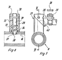
- a locking device 50 is fastened to the outer tube 48 and is constructed in the same way as the blocking devices. It has a housing 51 with an inclined surface 52 with which the inclined surface of an upper part 53 interacts.
- a locking bolt is fastened to the upper part, which is slidably mounted in the housing 51 and is loaded with a spring. The locking bolt engages in a locking recess 54 of an extendable part 55.
- the extendable part 55 is articulated on a bracket 15 of the backrest 1.
- a handle 56 is fastened to the upper part 53 and must be brought into the position shown in solid lines in FIG. 3 in order to initiate the locking of the parts 48 and 55 of the telescopic linkage.
- the locking device 50 for the telescopic linkage only snaps between the backrest and the lower leg rest when the backrest has assumed an inclined position of approximately 30 °. Only from this point in time is the lower leg rest 3 lowered when the backrest 1 is raised further.
- a Bowden cable 57 is provided, via which g nges 47 at the time of locking of the telescopic linkage Locking of the telescopic linkage 42 is made so that only the handle 56 needs to be actuated when switching to simultaneous actuation of the backrest 1 and the lower leg rest 3.
- the handle 56 is shown in FIG. 3 in dash-dotted lines in the position in which the locking devices of the telescopic linkage are released.
- the handle 56 is equipped with a stop arm 58 which cooperates with the front edge of the tab 12.
- the stop arm 58 works together with the bracket 12, so that the handle 56 is pivoted into the unlocked position.
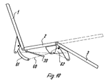
- the telescopic linkage 60 provided between the backrest 1 and the lower leg rest 3 assumes an acute angle in the horizontal position of the lying surface parts with respect to the lying surface.
- an arcuate arm 61 is attached, which projects with its free end into the area below the middle part 2 and to which the extendable part 62 of the telescopic linkage 60 is articulated.
- a bracket 63 is attached to the lower leg rest 3, to which the outer tube 64 of the telescopic linkage is articulated.
- the telescopic linkage is assigned a locking device 65, which is coupled via a Bowden cable 57 to the locking device 46 of the telescopic linkage 42 of the actuating device for the telescopic supports 8 and 9.
- the locking devices 65 and 46 can already be switched on in the horizontal position of the lying surface parts. During the entire adjustment movements of the backrest 1 and the lower leg rest 2, the locking devices 27 and 40 assigned to the telescopic supports 8, 9 are in the released position.
- the arrangement of the telescopic linkage 60 shown in FIGS. 8 to 10 ensures that when the backrest 1 is pivoted out of the horizontal position, the lower leg rest 3 initially does not move visibly. Only after a certain adjustment angle of the backrest 1 is the lower leg rest 3 pivoted more intensely.
- the lying surface parts 1, 2, 3 assume a sitting position for the patient.
- This illustration also shows that the middle part 2 has been moved into an inclined position.
Abstract
Description
Die Erfindung bezieht sich auf ein Krankenbett mit einer aus einer Rückenlehne, einem Mittelteil und einer Unterschenkellehne bestehenden Liegefläche, mit in einer Horizontalebene liegenden Drehachsen für die Rückenlehne und für die Unterschenkellehne und Gelenkachsen zwischen der Rückenlehne und dem Mittelteil und dem Mittelteil und der Unterschenkellehne, die im Raum zwischen den Drehachsen liegen und sich bewegen und mit zwei Teleskopstützen, die mit einem Ende am Mittelteil und mit dem anderen Ende an der Rückenlehne bzw. an der Unterschenkellehne angelenkt und über einen Handgriff betätigbar sind.The invention relates to a hospital bed with a lying surface consisting of a backrest, a middle part and a lower leg rest, with axes of rotation lying in a horizontal plane for the backrest and for the lower leg rest and articulated axes between the backrest and the middle part and the middle part and the lower leg rest lie and move in the space between the axes of rotation and with two telescopic supports which are articulated at one end to the middle part and at the other end to the backrest or lower leg rest and can be actuated via a handle.
Bei einem Krankenbett dieser Art sind die Unterschenkellehne und die Rückenlehne nur unabhängig voneinander verstellbar.In a sick bed of this type, the lower leg rest and the back rest can only be adjusted independently of one another.
Es ist ein Transportstuhl bekannt, bei dem die Liegefläche aus einer Unterschenkellehne, einem Mittelteil und einer Rückenlehne gebildet wird. Das Mittelteil, das an dem mit Bodenrohllen ausgerüsteten Fahrgestellt befestigt ist, behält bei allen Verstellbewegungen seine Lage bei. An dem Mittelteil sind die Unterschenkellehne und die Rückenlehne schwenkbar angelenkt und über eine Koppelstange verbunden. Durch die Koppelstange wird erreicht, daß bei einem Anheben der Rückenlehne gleichzeitig eine Absenken der Unterschenkellehne erfolgt. Wird die Rückenlehne aus der vertikalen Stellung in Richtung auf eine Schrägstellung verschwenkt, so wird die Unterschenkellehne nach oben geschwenkt. Eine Verstellbewegung des Mittelteils oder eine Verstellung der Rückenlehne oder der Unterschenkellehne allein sind bei dem bekannten Transportstuhl nicht möglich.A transport chair is known in which the lying surface is formed from a lower leg rest, a middle part and a back rest. The middle section, which is attached to the chassis equipped with floor rolls, maintains its position with all adjustment movements. To the The lower leg and the backrest are pivotally articulated and connected via a coupling rod. The coupling rod ensures that when the backrest is raised, the lower leg rest is simultaneously lowered. If the backrest is pivoted from the vertical position towards an inclined position, the lower legrest is pivoted upwards. An adjustment movement of the middle part or an adjustment of the backrest or the lower leg rest alone are not possible with the known transport chair.
Der Erfindung liegt die Aufgabe zugrunde, ein Krankenbett der eingangs genannten Art so zu gestalten, daß wahlweise die Unterschenkellehne mit der Rückenlehne synchron in entgegengesetzten Drehrichtungen oder die Unterschenkellehne und die Rückenlehne unabhängig voneinander verstellbar sind.The invention has for its object to design a patient bed of the type mentioned so that either the lower leg rest with the backrest synchronously in opposite directions of rotation or the lower leg rest and the backrest are independently adjustable.
Diese Aufgabe wird nach der Erfindung dadurch gelöst, daß die Betätigungseinrichtungen für die Tekskopstützen für eine gleichzeitige Betätigung koppelbar sind und zwischen der Rückenlehne und der Unterschenkellehne ein Teleskopgestänge mit einer Vorrichtung zum Arretieren der bewegbaren Gestängeteile vorgesehen ist.This object is achieved according to the invention in that the actuating devices for the Tekskopstützen can be coupled for simultaneous actuation and a telescopic linkage with a device for locking the movable linkage parts is provided between the backrest and the lower leg rest.
Bei einer vorteilhaften Ausführungsform der Erfindung sind die Vorrichtung zum Arretieren der Gestängeteile des Teleskopgestänges und die Kopplungsmittel für die Betätigungseinrichtungen der Teleskopstützen synchron über einen Bowdenzug betätigbar, der über einen Handgriff in seine Schaltstellungen gebracht werden kann.In an advantageous embodiment of the invention, the device for locking the linkage parts of the telescopic linkage and the coupling means for the actuating devices of the telescopic supports can be actuated synchronously via a Bowden cable, which can be brought into its switching positions via a handle.
Für das Pflegepersonal bzw. für den Patienten ist es somit sehr einfach, eine der Verstellmöglichkeiten der Liegeflächenteile auszuwählen.It is therefore very easy for the nursing staff or the patient to select one of the adjustment options for the lying surface parts.
Ausführungsbeispiele der Erfindung sind in den Zeichnungen dargestellt und werden im folgenden beschrieben.Embodiments of the invention are shown in the drawings and are described below.
Es zeigen:
- Fig. 1 die Liegeflächenteile in horizontaler Stellung in einer Seitenansicht,
- Fig. 2 den der Fig. 1 entsprechenden Grundriß,
- Fig. 3 eine Teilansicht der Fig. 1 in vergrößertem Maßstab,
- Fig. 4 eine Teilansicht der Fig. 2 in vergrößertem Maßstab,
- Fig. 5 einen Schnitt nach der Linie V-V in Fig. 4,
- Fig. 6 einen Schnitt nach der Linie VI-VI in Fig. 5,
- Fig. 7 einen Schnitt nach der Linie VII-VII in Fig. 3,
- Fig. 8 die Liegeflächenteile in horizontaler Lage mit einer gegenüber der Fig. 1 abgewandelten Betätigungseinrichtung,
- Fig. 9 einen Grundriß zu der Fig. 8 und
- Fig.10 die Liegeflächenteile bei einer Krankenbettkonstruktion nach den Fig. 8 und 9 in einer Seitzstellung.
- 1 the lying surface parts in the horizontal position in a side view,
- 2 the plan corresponding to FIG. 1,
- 3 is a partial view of FIG. 1 on an enlarged scale,
- 4 is a partial view of FIG. 2 on an enlarged scale,
- 5 shows a section along the line VV in Fig. 4,
- 6 shows a section along the line VI-VI in FIG. 5,
- 7 is a section along the line VII-VII in Fig. 3,
- 8 shows the lying surface parts in a horizontal position with an actuating device modified compared to FIG. 1,
- Fig. 9 is a plan view of Fig. 8 and
- 10 the lying surface parts in a bed construction according to FIGS. 8 and 9 in a lateral position.
Das in den Fig. 1 bis 4 aufgezeigte Krankenbett weist eine Rückenlehne 1, ein Mittelteil 2 und eine Unterschenkellehne 3 auf, die die Liegefläche des Krankenbettes bilden. Die Rückenlehne 1 ist in einer Gelenkachse 4 und die Unterschenkellehne 3 in einer Gelenkachse 5 am Mittelteil 2 schwenkbar angelenkt. Die Rückenlehne 1 ist um eine Achse 6 und die Unterschenkellehne 3 um eine Achse 7 im Gestell des Krankenbettes drehbar gelagert. Die Gelenkachsen 4 und 5 liegen im Raum zwisehen den Drehachsen 6 und 7 und bewegen sich auch in den verschiedenen Stellungen der Rückenlehne, des Mittelteils und der Unterschenkellehne in diesem Raum. Durch diese Anordnung der Gelenkachsen 4,5 zwischen der Rückenlehne 1 und dem Mittelteil 2 bzw. der Unterschenkellehne 3 und dem Mittelteil 2 in bezug auf die ortsfesten Drehachsen 6 und 7 besteht die Möglichkeit, daß der Patient mit seinem Körpergewicht die Verstellbewegungen der Liegeflächenteile unterstützt.The sick bed shown in FIGS. 1 to 4 has a backrest 1, a
Die Verstelleinrichtung des Krankenbettes weist zwei Teleskopstützen 8,9 auf, die mit ihren Aussenrohren 10, 11 am hinteren Ende an Laschen 12 angelenkt sind, die im Bereich ihrer Flansche 13 am Mittelteil 2 befestigt sind. Das ausfahrbare Rohr 14 der Teleskopstütze 8 ist an einer Konsole 15 angelenkt, die mit ihrem Befestigungsflansch 16 an der Rückenlehne 1 festgelegt ist. Das ausfahrbare Rohr 17 der Teleskopstütze 9 ist an einer Konsole 18 angelenkt, die mit ihrem Befestigungsflansch 19 an der Unterschenkellehne 3 festgelegt ist.The adjustment device of the hospital bed has two
Innerhalb der TeleskopstUtzen 8,9 können Kraftspeicher, z.B. ungesteuerte oder gesteuerte Gasfedern vorgesehen sein, durch die die Gewichte der zu verstellenden Liegeflächenteile kompensiert werden.Within the telescopic supports 8.9, energy stores, e.g. uncontrolled or controlled gas springs can be provided, by means of which the weights of the lying surface parts to be adjusted are compensated.
Die Betätigungseinrichtung für die Teleskopstützen 8,9 weist Handgriffe 20 auf, die untereinander über eine drehbar im Gestell des Krankenbettes gelagerte Welle 21 verbunden sind. Aus der Fig. 2 ergibt sich, daß die Handgriffe 20 von beiden Bettseiten betätigbar sind. An der Welle 21 ist ein Hebel 22 befestigt, der einen Zapfen 23 trägt, der in ein Langloch 24 einer Stange 25 eingreift, die zum Betätigungshebel 26 einer Blockiervorrichtung 27 der Teleskopstütze 8 führt. Die Blockiervorrichtung 27 weist einen Verriegelungsbolzen 28 auf, der in einem Gehäuse 29 geführt ist, das am Aussenrohr 10 der Teleskopstütze 8 befestigt ist. Der Bolzen ist über einen Querstift 30 am Oberteil 31 des Gehäuses festgelegt, welches eine Schrägfläche 32 aufweist, die unter dem gleichen Winkel verläuft wie eine Schrägfläche 33 des Gehäuses. Der Verriegelungsbolzen 28 weist einen Bund 34 auf, an dem sich eine zylindrische Schraubenfeder 35 abstützt. Das Rastende 36 des Verriegelungsbolzens greift in eine Rastaussparung 37 des ausfahrbaren Rohres 14 ein. Das ausfahrbare Rohr 14 ist miveiner Reihe von Rastaussparungen 37 versehen.The actuating device for the
Wird der Betätigungshebel 26 über die Stange 25 betätigt und gedreht, so bewegt sich der Verriegelungsbolzen 38 entgegen der Wirkung der Feder 35 nach oben und fährt mit seinem Rastende 36 aus der Rastaussparung 37. Das Rohr 14 kann nun aus dem Aussenrohr der Teleskopstütze gefahren und die Rückenlehne 1 verstellt werden.If the actuating
Aus der Fig. 4 ergibt sich, daß der Zapfen 23 mit einer Stange 38 gekoppelt ist, die parallel zu der Stange 25 verläuft und zu einem Betätigungshebel 39 einer Blockiervorrichtung 40 führt, die im gleichen Sinne wie die Blokkiervorrichtung 27 aufgebaut ist. Am Ende der Stange 38 ist ein Langloch 41 vorgesehen, durch das ein Leerhub gegenüber dem Betätigungshebel 39 erzielt wird, sofern die Welle 21 und der Hebel 22 in der Fig. 3 entgegen dem Uhrzeigersinn gedreht werden. In diesem Fall wird die Blokkiervorrichtung 27 in ihre entsperrte Stellung gebracht.From Fig. 4 it follows that the
Sofern in der Fig. 3 die Welle 21 und der mit ihr verbundene Hebel 22 im Uhrzeigersinn gedreht werden, wird über die Stange 38 die Blockiervorrichtung 40 in die entsperrte Stellung gebracht, während der Zapfen 23 im Langloch 24 einen Leerhub macht, so daß die Blockiervorrichtung 27 nicht getätigt wird. In diesem Fall gibt die Blokkiervorrichtung 40 das ausfahrbare Rohr 17 der Teleskopstütze 9 frei, so daß die Unterschenkellehne 3 verstellt werden kann.If the
Mit der bisher beschriebenen Betätigungsvorrichtung für die Teleskopstützen 8 und 9 ist es somit möglich, die Rückenlehne 1 und die Unterschenkellehne 3 unabhängig voneinander zu verstellen.With the previously described actuating device for the
Sofern eine synchrone Verstellbewegung der Rückenlehne 1 und der Unterschenkellehne 3, und zwar in entgegengesetzten Richtungen gewünscht wird,- beim Anheben der Rückenlehne wird die Unterschenkellehne abgesenkt bzw. beim Absenken der Rückenlehne wird die Unterschenkellehne angehoben - müssen die Blockiervorrichtungen 27 und 40 gleichzeitig gelöst werden und ferner muß zwischen der Rückenlehne und der Unterschenkellehne ein Teleskopgestänge arretiert werden.If a synchronous adjustment movement of the backrest 1 and the
Zwischen den Betätigungshebeln 26 und 39 der Blockiervorfrichtungen 27 und 40 ist ein Teleskopgestänge 42 angeordnet. In dem Aussenrohr 43, das mit seinem hinteren Ende am Betätigungshebel 39 angelenkt ist, ist eine Feder 44 vorgesehen, die sich mit einem Ende an der ausfahrbaren Stange 45 abstützt. Die ausfahrbare Stange 45 ist am Betätigungshebel 26 der Blockiervorrichtung 27 angelenkt. Die ausfahrbare Stange 45 ist über eine Arretiervorrichtung 46 gegenüber dem Aussenrohr festlegbar. Sofern das Teleskopgestänge 42 arretiert ist und eine Koppelstange zwischen den Betätigungshebeln 26 und 39 bildet, werden bei einer Betätigung des Handgriffs 20 die Blockiervorrichtungen 27 und 40 in eine entsperrte Stellung gebracht, so daß die Rückenlehne und die Unterschenkellehne gleichzeitig verstellt werden können.A
Zwischen der Rückenlehne 1 und der Unterschenkellehne 3 ist ein Teleskopgestänge 47 angeordnet. Das Aussenrohr 48 ist bei dem Ausführungsbeispiel als flaches Rechteckrohr ausgebildet und Uber einen Ausleger 49 an der Konsole 18 angelenkt. An dem Aussenrohr 48 ist eine Arretiervorrichtung 50 befestigt, die konstruktiv wie die Blockiervorrichtungen aufgebaut ist. Sie weist ein Gehäuse 51 mit einer Schräfgläche 52 auf, mit der die Schrägfläche eines Oberteils 53 zusammenwirkt. An dem Oberteil ist ein Verriegelungsbolzen befestigt, der in dem Gehäuse 51 gleitbar gelagert ist und mit einer Feder belastet wird. Der Verriegelungsbolzen greift in eine Rastaussparung 54 eines ausfahrbaren Teiles 55 ein. Das ausfahrbare Teil 55 ist an einer Konsole 15 der Rückenlehne 1 angelenkt.A
An dem Oberteil 53 ist ein Handgriff 56 befestigt, der in die in der Fig. 3 in ausgezogenen Linien aufgezeigte Stellung gebracht werden muß, um die Arretierung der Teile 48 und 55 des Teleskopgestänges in die Wege zu leiten.A
Bei dem Ausführungsbeispiel nach den Fig. 1 bis 7 rastet die Arretiervorrichtung 50 für das Teleskopgestänge zwischen der Rückenlehne und der Unterschenkellehne erst dann ein, wenn die Rückenlehne eine Schrägstellung von etwa 30° eingenommen hat. Erst von diesem Zeitpunkt an wird dann bei einem weiteren Anheben der Rückenlehne 1 die Unterschenkellehne 3 abgesenkt.In the embodiment according to FIGS. 1 to 7, the locking
Zwischen der Arretiervorrichtung 50 und .der Arretiervorrichtung 46 ist ein Bowdenzug 57 vorgesehen, über den im Zeitpunkt der Arretierung des Teleskopgestegnges 47 eine Arretierung des Teleskopgestänges 42 vorgenommen wird, so daß also bei der Umschaltung auf gleichzeitige Betätigung der Rückenlehne 1 und der Unterschenkellehne 3 nur der Handgriff 56 betätigt zu werden braucht.Between the
Der Handgriff 56 ist in der Fig. 3 in strichpunktierten Linien in der Stellung aufgezeigt, in der die Arretiervorrichtungen der Teleskopgestänge gelöst sind.The
Der Handgriff 56 ist, wie sich aus der Fig. 7 ergibt, mit einem Anschlag-ausleger 58 ausgerüstet, der mit der vorderen Kante der Lasche 12 zusammenarbeitet. Bei der Rückstellbewegung der Rückenlehne 1 in die horizontale Lage arbeitet der Anschlagausleger 58 mit der Lasche 12 zusammen, so daß der Handgriff 56 in die entsperrte Lage geschwenkt wird.7, the
Bei dem Ausführungsbeispiel nach den Fig. 8 bis 10 nimmt das zwischen der Rückenlehne 1 und der Unterschenkellehne 3 vorgesehene Teleskopgesteänge 60 in der horizontalen Lage der Liegeflächenteile gegenüber der Liegefläche einen spitzen Winkel ein. Dies kann aus der Fig. 8 entnommenwerden. An der Rückenlehne 1 ist ein bogenförmiger Ausleger 61 befestigt, der mit seinem freien Ende in den Bereich unterhalb des Mittelteils 2 ragt und an dem der ausfahrbare Teil 62 des Teleskopgestänges 60 angelenkt ist.In the exemplary embodiment according to FIGS. 8 to 10, the
An der Unterschenkellehne 3 ist eine Konsole 63 befestigt, an der das Aussenrohr 64 des Teleskopgestänges angelenkt ist. Dem Teleskopgestänge ist eine Arretiervorrichtung 65 zugeordnet, die über einen Bowdenzug 57 mit der Arretervorrichtung 46 des Teleskopgestänges 42 der Betätigungseinrichtung für die Teleskopstützen 8 und 9 gekoppelt ist.A
Durch die gewählte Anordnung des TeleskogestHnges 60 können die Arretiervorrichtung 65 und 46 schon in der Horizontallage der Liegeflächenteile eingeschaltet werden. Während der gesamten Verstellbewegungen der Rückenlehne 1 und der Unterschenkellehne 2 sind die den Teleskopstützen 8,9 zugeordneten Blockiervorrichtungen 27 und 40 in der gelösten Stellung.Due to the selected arrangement of the
Durch die in den Fig. 8 bis 10 aufgezeigte Anordnung des Teleskopgestänges 60 wird erreicht, daß bei einer Verschwenkung der Rückenlehne 1 aus der horizontalen Lage sich die Unterschenkellehne 3 zunächst nicht sichtbar bewegt. Erst nach einem bestimmten Verstellwinkel der Rückenlehne 1 wird auch die Unterschenkellehne 3 intensiver verschwenkt.The arrangement of the
In der Fig. 10 nehmen die Liegeflächenteile 1,2,3 eine Sitzstellung für den Patienten ein. Aus dieser Darstellung ergibt sich auch, daß das Mittelteil 2 in eine Schräglage bewegt wurde.10, the lying
- 1 Rückenlehne 1 backrest
- 2 Mittelteil 2 middle section
- 3 Unterschenkellehne 3 lower leg rest
- 4 Gelenkachse 4 hinge axis
- 5 Gelenkachse 5 hinge axis
- 6 Drehachse 6 axis of rotation
- 7 Drehachse 7 axis of rotation
- 8 Teleskopstütze 8 telescopic support
- 9 Teleskopstütze 9 telescopic support
- 10 Außenrohr 10 outer tube
- 11 Außenrohr 11 outer tube
- 12 Lasche 12 tab
- 13 Flansch 13 flange
- 14 ausfahrbares Rohr 14 extendable tube
- 15 Konsole 15 console
- 16 Befestigungsflansch 16 mounting flange
- 17 ausfahrbares Rohr 17 extendable tube
- 18 Konsole 18 console
- 19 Befestigungsflansch 19 mounting flange
- 20 Handgriff 20 handle
- 21 Welle 21 wave
- 22 Hebel 22 levers
- 23 Zapfen 23 cones
- 24 Langloch 24 slot
- 25 Stange 25 bar
- 26 Betätigungshebel 26 operating lever
- 27 Blockiervorrichtung 27 blocking device
- 28 Verriegelungsbolzen 28 locking bolts
- 29 Gehäuse 29 housing
- 30 Querstift 30 cross pin
- 31 Oberteil 31 top
- 32 Schrägfläche 32 sloping surface
- 33 Schrägfläche33 sloping surface
- 34 Bund34 fret
- 35 Feder35 spring
- 36 Rastende36 stops
- 37 Rastaussparung37 notch
- 38 Stange38 bar
- 39 Betätigungshebel39 operating lever
- 40 Blockiervorrichtung40 blocking device
- 41 Langloch41 slot
- 42 Teleskopgestänge 42 telescopic rods
- 43 Aussenrohr43 outer tube
- 44 Feder44 spring
- 45 Stange45 bar
- 46 Arretiervorrichtung46 locking device
- 47 Teleskopgestänge47 telescopic rods
- 48 Aussenrohr48 outer tube
- 49 Ausleger49 outriggers
- 50 Arretiervorrichtung50 locking device
- 51 Gehäuse51 housing
- 52 Schrägfläche52 sloping surface
- 53 Oberteil53 top
- 54 Rastaussparung54 notch
- 55 ausfahrbares Teil55 extendable part
- 56 Handgriff56 handle
- 57 Bowdenzug57 Bowden cable
- 58 Anschlagausleger58 stop arm
- 59 ---59 ---
- 60 Teleskopgestänge60 telescopic rods
- 61 Ausleger61 outriggers
- 62 ausfahrbares Teil62 extendable part
- 63 Konsole63 console
- 64 Aussenrohr64 outer tube
- 65 Arretiervorrichtung65 locking device
Claims (12)
Applications Claiming Priority (2)
| Application Number | Priority Date | Filing Date | Title |
|---|---|---|---|
| DE19782811409 DE2811409C2 (en) | 1978-03-16 | 1978-03-16 | Sickbed |
| DE2811409 | 1978-03-16 |
Publications (3)
| Publication Number | Publication Date |
|---|---|
| EP0004282A2 true EP0004282A2 (en) | 1979-10-03 |
| EP0004282A3 EP0004282A3 (en) | 1979-10-31 |
| EP0004282B1 EP0004282B1 (en) | 1981-03-04 |
Family
ID=6034597
Family Applications (1)
| Application Number | Title | Priority Date | Filing Date |
|---|---|---|---|
| EP19790100471 Expired EP0004282B1 (en) | 1978-03-16 | 1979-02-19 | Hospital bed |
Country Status (4)
| Country | Link |
|---|---|
| EP (1) | EP0004282B1 (en) |
| AT (1) | AT365921B (en) |
| DE (1) | DE2811409C2 (en) |
| ES (1) | ES242039Y (en) |
Families Citing this family (5)
| Publication number | Priority date | Publication date | Assignee | Title |
|---|---|---|---|---|
| DE2913712C2 (en) * | 1979-04-05 | 1987-12-23 | Joh. Stiegelmeyer & Co Gmbh, 4900 Herford | Sickbed |
| DE2943546C2 (en) * | 1979-10-27 | 1985-04-25 | L. & C. Arnold Gmbh, 7060 Schorndorf | Sickbed |
| DE3703433C3 (en) * | 1987-02-05 | 1996-08-08 | Wissner Bosserhoff Gmbh | Sick bed with motorized or mechanically tiltable back frame |
| US5105486A (en) * | 1990-06-18 | 1992-04-21 | Joerns Healthcare Inc. | Adjustable bed |
| DE19544250C1 (en) * | 1995-11-28 | 1997-05-28 | Stiegelmeyer & Co Gmbh | Bed for use by patients |
Citations (6)
| Publication number | Priority date | Publication date | Assignee | Title |
|---|---|---|---|---|
| DE192249C (en) * | ||||
| DE540623C (en) * | 1928-07-19 | 1932-01-09 | Everitt S Patents Company Ltd | Adjustable bed frame |
| DE662465C (en) * | 1935-10-09 | 1938-07-14 | John Eriksen | Mattresses, especially for hospital beds |
| US2620489A (en) * | 1946-07-13 | 1952-12-09 | Luther E Holm | Hospital bed adjusting mechanism |
| US3127619A (en) * | 1958-06-02 | 1964-04-07 | United States Bedding Co | Contour bed |
| DE2311607A1 (en) * | 1973-03-09 | 1974-09-19 | Bremshey Ag | BED, ESPECIALLY SICK BED |
-
1978
- 1978-03-16 DE DE19782811409 patent/DE2811409C2/en not_active Expired
-
1979
- 1979-02-19 EP EP19790100471 patent/EP0004282B1/en not_active Expired
- 1979-02-22 AT AT138779A patent/AT365921B/en not_active IP Right Cessation
- 1979-03-14 ES ES1979242039U patent/ES242039Y/en not_active Expired
Patent Citations (6)
| Publication number | Priority date | Publication date | Assignee | Title |
|---|---|---|---|---|
| DE192249C (en) * | ||||
| DE540623C (en) * | 1928-07-19 | 1932-01-09 | Everitt S Patents Company Ltd | Adjustable bed frame |
| DE662465C (en) * | 1935-10-09 | 1938-07-14 | John Eriksen | Mattresses, especially for hospital beds |
| US2620489A (en) * | 1946-07-13 | 1952-12-09 | Luther E Holm | Hospital bed adjusting mechanism |
| US3127619A (en) * | 1958-06-02 | 1964-04-07 | United States Bedding Co | Contour bed |
| DE2311607A1 (en) * | 1973-03-09 | 1974-09-19 | Bremshey Ag | BED, ESPECIALLY SICK BED |
Also Published As
| Publication number | Publication date |
|---|---|
| EP0004282A3 (en) | 1979-10-31 |
| EP0004282B1 (en) | 1981-03-04 |
| ATA138779A (en) | 1981-07-15 |
| ES242039Y (en) | 1979-12-01 |
| DE2811409A1 (en) | 1979-09-20 |
| DE2811409C2 (en) | 1982-04-15 |
| ES242039U (en) | 1979-07-01 |
| AT365921B (en) | 1982-02-25 |
Similar Documents
| Publication | Publication Date | Title |
|---|---|---|
| EP0159562B1 (en) | Lifting chair | |
| DE3031435A1 (en) | ADJUSTABLE CHAIR BY SWIVELING | |
| DE1283458B (en) | Armchair with a retractable and extendable leg support | |
| EP0172528B1 (en) | Coupler frame with at least one hook | |
| DE3309174C1 (en) | Bed side part | |
| EP0098414B1 (en) | Height adjustment device for motor vehicle seats | |
| DE1529675B1 (en) | Vertically adjustable bed table | |
| DE1162981B (en) | Lever adjustment gear for reclining chairs with swiveling leg supports | |
| DE2102911B2 (en) | MAWERK | |
| EP0004282B1 (en) | Hospital bed | |
| DE2913712C2 (en) | Sickbed | |
| DE4236195C2 (en) | Sick or nursing bed | |
| DE3249163C2 (en) | ||
| DE3322017C2 (en) | ||
| EP0399618A1 (en) | Bed | |
| EP1284710B1 (en) | Birthing chair | |
| DE7807972U1 (en) | Sickbed | |
| EP0088957B1 (en) | Dental treatment chair | |
| EP0553418B1 (en) | Table with a vertically adjustable and tiltable top | |
| DE2318815C2 (en) | Fold-up lounge furniture with a table | |
| DE2640895B2 (en) | Bunk for the driver's cab of a motor vehicle | |
| EP3530552B1 (en) | Driver`s cabin | |
| DE4242507C2 (en) | Sick bed | |
| DE2944940C2 (en) | Device for the lateral separation of neighboring cattle stalls | |
| DE2028417C3 (en) | Weighing device for beds |
Legal Events
| Date | Code | Title | Description |
|---|---|---|---|
| PUAI | Public reference made under article 153(3) epc to a published international application that has entered the european phase |
Free format text: ORIGINAL CODE: 0009012 |
|
| PUAL | Search report despatched |
Free format text: ORIGINAL CODE: 0009013 |
|
| AK | Designated contracting states |
Designated state(s): BE CH FR IT LU NL |
|
| AK | Designated contracting states |
Designated state(s): BE CH FR IT LU NL |
|
| 17P | Request for examination filed | ||
| ITF | It: translation for a ep patent filed |
Owner name: STUDIO INGG. FISCHETTI & WEBER |
|
| GRAA | (expected) grant |
Free format text: ORIGINAL CODE: 0009210 |
|
| AK | Designated contracting states |
Designated state(s): BE CH FR IT LU NL |
|
| PLBI | Opposition filed |
Free format text: ORIGINAL CODE: 0009260 |
|
| PGFP | Annual fee paid to national office [announced via postgrant information from national office to epo] |
Ref country code: FR Payment date: 19820120 Year of fee payment: 4 |
|
| 26 | Opposition filed |
Opponent name: L. & C. ARNOLD GMBH Effective date: 19811129 |
|
| PGFP | Annual fee paid to national office [announced via postgrant information from national office to epo] |
Ref country code: LU Payment date: 19820217 Year of fee payment: 4 |
|
| PG25 | Lapsed in a contracting state [announced via postgrant information from national office to epo] |
Ref country code: LU Free format text: LAPSE BECAUSE OF NON-PAYMENT OF DUE FEES Effective date: 19820228 |
|
| PGFP | Annual fee paid to national office [announced via postgrant information from national office to epo] |
Ref country code: NL Payment date: 19820228 Year of fee payment: 4 |
|
| PGFP | Annual fee paid to national office [announced via postgrant information from national office to epo] |
Ref country code: CH Payment date: 19820331 Year of fee payment: 4 Ref country code: BE Payment date: 19820331 Year of fee payment: 4 |
|
| PG25 | Lapsed in a contracting state [announced via postgrant information from national office to epo] |
Ref country code: BE Effective date: 19830219 |
|
| PG25 | Lapsed in a contracting state [announced via postgrant information from national office to epo] |
Ref country code: CH Effective date: 19830228 |
|
| PG25 | Lapsed in a contracting state [announced via postgrant information from national office to epo] |
Ref country code: NL Effective date: 19830901 |
|
| NLV4 | Nl: lapsed or anulled due to non-payment of the annual fee | ||
| PG25 | Lapsed in a contracting state [announced via postgrant information from national office to epo] |
Ref country code: FR Free format text: LAPSE BECAUSE OF NON-PAYMENT OF DUE FEES Effective date: 19831031 |
|
| REG | Reference to a national code |
Ref country code: CH Ref legal event code: PL |
|
| REG | Reference to a national code |
Ref country code: FR Ref legal event code: ST |
|
| PLBN | Opposition rejected |
Free format text: ORIGINAL CODE: 0009273 |
|
| STAA | Information on the status of an ep patent application or granted ep patent |
Free format text: STATUS: OPPOSITION REJECTED |
|
| 27O | Opposition rejected |
Effective date: 19840606 |