EP0004176A1 - Appareil et procédé pour le traitement de plaques d'impression en photopolymères - Google Patents
Appareil et procédé pour le traitement de plaques d'impression en photopolymères Download PDFInfo
- Publication number
- EP0004176A1 EP0004176A1 EP79300336A EP79300336A EP0004176A1 EP 0004176 A1 EP0004176 A1 EP 0004176A1 EP 79300336 A EP79300336 A EP 79300336A EP 79300336 A EP79300336 A EP 79300336A EP 0004176 A1 EP0004176 A1 EP 0004176A1
- Authority
- EP
- European Patent Office
- Prior art keywords
- plate
- container
- solvent
- holder
- flat plate
- Prior art date
- Legal status (The legal status is an assumption and is not a legal conclusion. Google has not performed a legal analysis and makes no representation as to the accuracy of the status listed.)
- Withdrawn
Links
Images


Classifications
-
- G—PHYSICS
- G03—PHOTOGRAPHY; CINEMATOGRAPHY; ANALOGOUS TECHNIQUES USING WAVES OTHER THAN OPTICAL WAVES; ELECTROGRAPHY; HOLOGRAPHY
- G03F—PHOTOMECHANICAL PRODUCTION OF TEXTURED OR PATTERNED SURFACES, e.g. FOR PRINTING, FOR PROCESSING OF SEMICONDUCTOR DEVICES; MATERIALS THEREFOR; ORIGINALS THEREFOR; APPARATUS SPECIALLY ADAPTED THEREFOR
- G03F7/00—Photomechanical, e.g. photolithographic, production of textured or patterned surfaces, e.g. printing surfaces; Materials therefor, e.g. comprising photoresists; Apparatus specially adapted therefor
- G03F7/26—Processing photosensitive materials; Apparatus therefor
- G03F7/30—Imagewise removal using liquid means
- G03F7/3085—Imagewise removal using liquid means from plates or webs transported vertically; from plates suspended or immersed vertically in the processing unit
Definitions
- This invention relates to apparatus and a method of processing photopolymer printing plates in particular apparatus including a container for holding solvent fluid, a holder adapted to hold, within the container, a flat plate to be washed out with face portions to be selectively removed under the joint action of the solvent within the container and a mechanical scouring action, brush means held adjacent the flat plate face location, and means adapted to provide relative movement between flat plate held within the container and the brush means to effect the said scouring action.
- the problem comes from the difficulty of being able to ensure that any mechanical member for instance, a brush fibre is used in such a way and under such controlled pressure that even the finest projections on for instance, a printing plate, will not be inadvertently removed by undue pressure at any location on the plate.
- the problem is to have such action uniform over a large plate area where the plate area may comprise separate segments which are separated by quite deep channels and which may have significantly higher or lower faces.
- Some objects of this invention which relate to improvements in general terms to apparatus suitable for this application, include the object of providing a flat plate wash out apparatus which can be used with very highly volatile solvents and which will offer an adequate wash out effect without promoting as much vapourization as has hitherto been the case of the solvent, or assists in providing means by which such vapourization can be minimised.
- the means providing the mechanical agitation during the wash out action can achieve an action which is more uniform than has hitherto been the case, and such can be achieved in an economic and practical manner, and moreover, can be achieved in such a way that it facilitates also the minimization of vapourization.
- a further object of this invention is to provide drive means for effecting the mechanical movement of the wash out members which firstly still maintain the advantages of not promoting any electrical sparking, therefore providing no hazard,but at the same time, secondarily, providing in economic and practical manner a drive action that is both effective for good wash out and incidentally, can be used for additional support in access to portions of the machines.
- a furtherrobject of this invention is to propose a machine which can in economical manner and in such a way as to take a minimum of floor space, handle, in as quick a time as possible, the washing out of plates in an adequate way and especially provide that plates requiring different solvents may be in an economical way be able to be handled with wash out at the same time with the same machine.
- a flat-plate wash out apparatus of a type including a container for holding solvent fluid, a holder within the container to hold a flat plate for washing out purposes, with face portions to be selectively removed under the joint actions of the solvent within the container and a mechanical scouring action, brush means held adjacent the flat plate face location, and means adapted to provide relative movement between any flat plate held within the container and the brush means to effect the said scouring action,
- the apparatus being characterized according to this invention in that the brush means include a pliable sheet located behind brush-out fingers projecting toward the face of a flat plate when held appropriately in the holder, and distributed pressure means behind the said pliable sheet to provide substantially uniform pressure against the pliable sheet.
- the tension can be caused then by simply holding the sheet and allowing the pressure from behind to apply the pressure or additional spring means to apply tension to hold the pliable sheet in position.
- a "pliable" sheet that is a sheet-which will have no significant resilient reaction when deflected in a direction transverse to its planar position, ensures that the pressure is in effect applied by the numerous spring elements or distributed spring pressure or distributed resilient pressure behind the pliable sheet, and the pliable sheet protects these elements from this tipping effect.
- the flat plate holding means are adapted to hold a flat plate which the plane of the plate in a vertical or substantially vertical orientation while being within solvent held within a container and the appropriate wash out mechanism is accordingly adapted to be effective while the flat plate is in such orientation.
- the surface of any solvent fluid will be substantially without significant agitation or at least minimal agitation, and of course the surface area in itself is significantly reduced as compared to horizontal layouts.
- the invention can be said to reside in a flat--plate wash out apparatus of a type which includes a container for holding solvent fluid, and drive means to effect a relative wash out movement between a plate held in plate holding means and brush means, while the plate is within solvent fluid held in a container, the apparatus being characterized in that the plate holding means are adapted to hold any flat plate, in a position in.solvent fluid in the container, in a substantially vertical orientation while being subject to wash out action from the brush means.
- the apparatus is further characterised in that drive means effecting relative wash out movement include a pneumatic or hydraulic ram, a supply of pneumatic or hydraulic fluid at an above atmospheric pressure, and valve means to control the supply of the said fluid to the ram upon a selection of valve positions, so as to effect a to and fro action which is, by coupling means, transferred to the plate holding means, so as to result in an upward and downward wash out movement relative to the brush means.
- drive means effecting relative wash out movement include a pneumatic or hydraulic ram, a supply of pneumatic or hydraulic fluid at an above atmospheric pressure, and valve means to control the supply of the said fluid to the ram upon a selection of valve positions, so as to effect a to and fro action which is, by coupling means, transferred to the plate holding means, so as to result in an upward and downward wash out movement relative to the brush means.
- the brush means, together with the pliable sheet that might be used are together constituted by being a respective portions of plush.
- the distributed pressure means behind the pliable sheet comprises sac having fluid therein under pressure whereby to cause the necessary uniform pressure against the pliable sheet.
- the drive means include a rod, raised and lowered by the ram, and valve means selectable so that in one selected position, the rod being coupled to the plate holding means, will effect a lifting of such plate holding means, out from a position within the container, to assist in relocation of plates to be washed out.
- a further preferable feature the arrangement in which there are two containers for holding solvent fluid, and each includes means as hitherto characterized, the two containers being in an adjacent location, one to the other, and each drive means being effected by a common pneumatic or hydraulic drive ram.
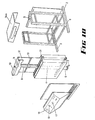
- a housing 1 which includes feet 2 and 3 adapted to provide stable support for ; the housing 1 in the apparent vertical position as shown.
- a centrally located pneumatically operable ram 4 which has a cylinder 5 supported at a lower end to a frame 6 of the housing and which has the supply of hydraulic fluid connected by a conduit 7 through control valve 8.
- Control valve 8 is a three-way valve having three positions, one being a wash.out position, a second being a raised position, and a third being a release position.
- a piston within the hydraulic ram 4 is connected to piston rod 9 an upper end of which is secured to a plate holder support arm 10.
- This arm 10 is in the form of a "U" shaped member in cross section and each of the legs of the "U” shape provide support for one or other of the plate holders 11 and 12.
- Each plate holder comprises a metal sheet of appropriately anti-corrosive material such as stainless steel suitably reinforced by reinforcing packing bars 13.
- both 11 and 12 plate clamps 13 being the upper plate clamps
- 14 being the lower plate clamps and each of these can be opened by twisting of cam member 15 to allow for location of a plate such as a photopolymer plate therein, after which the cam is reorientated to allow the spring action of the plate j clamp to take over and grab the appropriate end of the plate.
- a control panel 16 includes a mechanical timer connected to the fluid pressure supply so that the time for the operation cycle can be preset and after which an audible signal can be given such as a bell.
- the control for this is shown at 17, also there is shown a pressure indicator for indicating the pressure of the supply air for operating the pneumatic ram and the indicator 19 indicates the existing head of solvent within each container so as to warn if the level of solvent falls below a selected minimum.
- the means providing such indication are now shown in detail for sake of simplicity of the drawings, but are simply a float control with indicator mechanically coupled to the reading device.
- the means to apply the scouring action and providing pressure for projecting fingers against any plate held by the plate holder are generally held on a separable assembly 20 which includes a frame 21 having outwardly projecting arms 22 which support through locating pins 23 a plush frame 24.
- the plush frame comprises a rectangular frame constructed of square cross section non-corrosive metal such as high quality stainless steel and has stretched across its opening area, plush which is secured by suitable cross bar and screws at an upper end 25 and at a lower end 26 ⁇ .
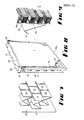
- plush is a well known and accepted term within the art and comprises a number of outwardly projecting fingers which provide brush out means each of which are bound to a fabric base in a which provides a pliable sheet supporting overall the projecting fingers shown in Pig. 9 especially as 26.
- a plurality of springs 27 each of these comprising a member constructed of sheet stainless steel and being bent into the form of a "W" having one leg secured to a backing plate 28 and of course having a forward leg 29 adjacently plush so as to provide an outward pressure against the plush.
- Each of the legs 29 are of rectangular proportions and are interlocked and in adjacent relationship to the other plates 29 as is shown especially in Fig. 7.
- the assembly 20 is duplicated, and there is one such assembly for each of the containers 30 and 31 and these are secured to the container by having an upper lip 32 fitting over the respective side wall of the respective container either 30 or 31.
- the assembly 20 is secured in this position by having appropriate screws passing through apertures 33 into the appropriate side wall portion of the container.
- a lid 34 covers both of the containers 30 and 31.
- Fig. 14 there is shown an upper trip valve 34 and a lower trip valve 35 which are activated by bearing against a trip arm 36 which is attached to the plate holder support arm 10.
- trip valves 34 and 35 act in conjunction wirth the control valve 8 so that when the control valve 8 is in the wash out position, this connects the pneumatic supp conduit through these valves and then to the supply cosnduit 7 supplying the pneumatic ram 4.
- the upper plate holder support arm 10 carries with it the cover 34.
- the means supplying pressure to the pliable sheet which of course includes the plush in this case can be varied according to a second and third preferred embodiment and according to the second embodiment, such means include a flexible sac as shown in Fig. 11 and 12 at 37.
- a frame backing 38 assists in ensuring that the sac 37 need not be of undue width and furthermore an extension to the sac 39 through a connecting conduit 40 provides that a head of fluid within the sac 37 can provide the necessary outward pressure.
- the walls of the sac 37 are comprised of a material such as pliable plastic which while being resistant to any solvent action, can nonetheless hold the fluid pressure and be used to supply the pressure against the plush.
- the container 41 also includes the plush holder 42 and the plate holder 43.
- FIG. 13 this is a third embodiment showing a sac 44 which this time is purely a closed sac and there is behind this a plate 45 which is subject to pressure by reason of spring 46 and 47 which therefore provides the uniform spreading of any pressure across the plush 48 against plate 49 in container 50.
- the two containers 30 and 31 are each in adjacent location and of common height and generally in parallel one with respect to the other and are separated by a hydraulic or pneumatic ram in this case, a pneumatic ram, whereby the drive means connected through the mechanical linkage of the plate holder support arm 10 and the plate holder 11 or 12 provides an upward and downward wash out scouring motion.
- the containers, especially 30 and 31 will be seen to provide support for use with the plates during the wash out action being held generally vertical, and of course the orientation in itself need not be strictly vertical but can vary considerably perhaps as much as 20 to 30 degrees from the vertical, however, the main direction being vertical and of course having a very small upper surface area for exposure to the air, or perhaps more importantly, that all of the action occurs below the surface of the solvent but perhaps more importantly most of the mechanical action occurs deep below the surface, and therefore it is possible to provide a covering fluid which will not be substantially mixed into the surface of the solvent.
- the invention can include the concept therefore of providing an additional blanket fluid above any solvent within a container for this purpose.
- a significant feature is also the arrangement of two containers, so that at any one time, either twice the cleaning action available from one container alone, is available, or one of the containers can have one solvent and perhaps a different solvent in the other container so that different plates can be processed at the same time.
Landscapes
- Physics & Mathematics (AREA)
- General Physics & Mathematics (AREA)
- Inking, Control Or Cleaning Of Printing Machines (AREA)
- Photographic Processing Devices Using Wet Methods (AREA)
- Photosensitive Polymer And Photoresist Processing (AREA)
Applications Claiming Priority (6)
| Application Number | Priority Date | Filing Date | Title |
|---|---|---|---|
| AU3616/78 | 1978-03-07 | ||
| AU361678 | 1978-03-07 | ||
| AU5032/78 | 1978-07-11 | ||
| AU503278 | 1978-07-11 | ||
| AU6912/78 | 1978-11-27 | ||
| AU691278 | 1978-11-27 |
Publications (1)
| Publication Number | Publication Date |
|---|---|
| EP0004176A1 true EP0004176A1 (fr) | 1979-09-19 |
Family
ID=27151502
Family Applications (1)
| Application Number | Title | Priority Date | Filing Date |
|---|---|---|---|
| EP79300336A Withdrawn EP0004176A1 (fr) | 1978-03-07 | 1979-03-06 | Appareil et procédé pour le traitement de plaques d'impression en photopolymères |
Country Status (3)
| Country | Link |
|---|---|
| US (1) | US4218799A (fr) |
| EP (1) | EP0004176A1 (fr) |
| JP (1) | JPS54127705A (fr) |
Families Citing this family (2)
| Publication number | Priority date | Publication date | Assignee | Title |
|---|---|---|---|---|
| JPH01160443U (fr) * | 1988-04-25 | 1989-11-07 | ||
| CN110699723B (zh) * | 2019-03-25 | 2020-11-06 | 义乌市鼎莎针织有限公司 | 一种提升镀层质量的电刷镀装置 |
Citations (7)
| Publication number | Priority date | Publication date | Assignee | Title |
|---|---|---|---|---|
| US2677320A (en) * | 1946-12-23 | 1954-05-04 | John S Swift Co Inc | Developing head for phtolithographic plate treating machines |
| GB920130A (en) * | 1959-04-06 | 1963-03-06 | Hans Hoerner | Improvements in or relating to a photographic process of making a printing plate, block or mould with raised elements |
| FR1403252A (fr) * | 1963-07-06 | 1965-06-18 | Basf Ag | Procédé pour la fabrication de clichés |
| DE1597802A1 (de) * | 1967-07-21 | 1970-08-27 | Wiladon Kunststoff Vertriebs G | Verfahren und Vorrichtung zum Auswaschen von Fotopolymer-Druckplatten |
| US3916426A (en) * | 1974-07-01 | 1975-10-28 | Polychrome Corp | Apparatus for developing offset printing plates |
| US3943539A (en) * | 1974-10-02 | 1976-03-09 | Polychrome Corporation | Vertical plate processor |
| DE2614624A1 (de) * | 1975-04-03 | 1976-10-21 | Blight Alison Mary | Vorrichtung zum auswaschen des unpolymerisierten bestandteils einer fotopolymerisat-druckplatte |
Family Cites Families (4)
| Publication number | Priority date | Publication date | Assignee | Title |
|---|---|---|---|---|
| AU146894B2 (en) * | 1950-05-18 | 1951-04-19 | John Maurice Bayley | Improvements in or relating to apparatus for cleaning sheet glass, plastic, or other like material |
| GB1289914A (fr) * | 1970-05-19 | 1972-09-20 | ||
| JPS598505B2 (ja) * | 1975-09-13 | 1984-02-24 | 同和鉱業 (株) | 金属電解精錬用カソ−ドの研磨装置 |
| JPS5387904A (en) * | 1977-01-13 | 1978-08-02 | Mitsui Mining & Smelting Co | Apparatus for grinding electrolysis matrixplate |
-
1979
- 1979-03-06 US US06/017,891 patent/US4218799A/en not_active Expired - Lifetime
- 1979-03-06 EP EP79300336A patent/EP0004176A1/fr not_active Withdrawn
- 1979-03-07 JP JP2659579A patent/JPS54127705A/ja active Pending
Patent Citations (7)
| Publication number | Priority date | Publication date | Assignee | Title |
|---|---|---|---|---|
| US2677320A (en) * | 1946-12-23 | 1954-05-04 | John S Swift Co Inc | Developing head for phtolithographic plate treating machines |
| GB920130A (en) * | 1959-04-06 | 1963-03-06 | Hans Hoerner | Improvements in or relating to a photographic process of making a printing plate, block or mould with raised elements |
| FR1403252A (fr) * | 1963-07-06 | 1965-06-18 | Basf Ag | Procédé pour la fabrication de clichés |
| DE1597802A1 (de) * | 1967-07-21 | 1970-08-27 | Wiladon Kunststoff Vertriebs G | Verfahren und Vorrichtung zum Auswaschen von Fotopolymer-Druckplatten |
| US3916426A (en) * | 1974-07-01 | 1975-10-28 | Polychrome Corp | Apparatus for developing offset printing plates |
| US3943539A (en) * | 1974-10-02 | 1976-03-09 | Polychrome Corporation | Vertical plate processor |
| DE2614624A1 (de) * | 1975-04-03 | 1976-10-21 | Blight Alison Mary | Vorrichtung zum auswaschen des unpolymerisierten bestandteils einer fotopolymerisat-druckplatte |
Also Published As
| Publication number | Publication date |
|---|---|
| US4218799A (en) | 1980-08-26 |
| JPS54127705A (en) | 1979-10-03 |
Similar Documents
| Publication | Publication Date | Title |
|---|---|---|
| JP3930069B2 (ja) | オフセットまたは凸版印刷機のためのインキつぼ | |
| EP0004176A1 (fr) | Appareil et procédé pour le traitement de plaques d'impression en photopolymères | |
| US3642013A (en) | Apparatus for cleaning hollow cylinders and the like | |
| DE2250279B2 (de) | Vorrichtung zur behandlung von druckplatten | |
| US5713277A (en) | Combination print head and pivotable print screen holder and method for improved operator safety during screen maintenance | |
| WO1991007159A1 (fr) | Chariot de desinfection pour hopital | |
| JPH06155718A (ja) | 輪転印刷機用のインキ溝を空にする方法及びその実施装置とドクター | |
| US3589287A (en) | Rotogravure ink fountain with cover-lifting system | |
| DE4040553A1 (de) | Vorrichtung zum reinigen der innenseiten eines behaelters, insbesondere eines mischbehaelters | |
| KR0162728B1 (ko) | 회전 인쇄기의 잉킹장치를 세척하는 장치 | |
| FR2729332A1 (fr) | Procede et dispositif pour maintenir et nettoyer un dispositif de mesure d'un parametre d'une encre d'imprimerie | |
| DE3601539A1 (de) | Vorrichtung zum reinigen des uebertragzylinders einer druckerpresse | |
| US4574698A (en) | Apparatus for servicing printing press | |
| US3751208A (en) | Vacuum forming machine | |
| EP0572713A1 (fr) | Appareil pour ouvrir des emballages durs et compressibles ou des sachets flexibles | |
| DE3141495C2 (de) | Gerätewagen für Reinigungszwecke | |
| JPS5555871A (en) | Automatic washing machine for ink rollor | |
| CS209802B2 (en) | Washer of the transferring roller of the printing machine | |
| DE3103720C2 (de) | Gerät zum Reinigen von im aufgehängten Zustand belassenen Gardinen und dergleichen | |
| US2985103A (en) | Automatic inking system wash-up | |
| CH425600A (de) | Vorrichtung zum Herstellen eines örtlich festgelegten, geprägten bzw. gedruckten, in bestimmten Intervallen sich wiederholenden Musters auf einer sich bewegenden Bahn eines Flächengebildes | |
| JPH081861Y2 (ja) | 印刷装置のカ−トリツジ構造 | |
| CN214918622U (zh) | 一种印刷ps版冲洗装置 | |
| JPH0446273Y2 (fr) | ||
| JPH05245449A (ja) | 洗浄籠の作動装置 |
Legal Events
| Date | Code | Title | Description |
|---|---|---|---|
| PUAI | Public reference made under article 153(3) epc to a published international application that has entered the european phase |
Free format text: ORIGINAL CODE: 0009012 |
|
| AK | Designated contracting states |
Designated state(s): BE CH DE FR GB IT NL SE |
|
| 17P | Request for examination filed | ||
| STAA | Information on the status of an ep patent application or granted ep patent |
Free format text: STATUS: THE APPLICATION IS DEEMED TO BE WITHDRAWN |
|
| 18D | Application deemed to be withdrawn |
Effective date: 19830328 |
|
| RIN1 | Information on inventor provided before grant (corrected) |
Inventor name: BLIGHT, LANGDON ROSS |