DE10055152B4 - Ventilation system of a lamp, in particular a headlight for vehicles - Google Patents
Ventilation system of a lamp, in particular a headlight for vehicles Download PDFInfo
- Publication number
- DE10055152B4 DE10055152B4 DE10055152A DE10055152A DE10055152B4 DE 10055152 B4 DE10055152 B4 DE 10055152B4 DE 10055152 A DE10055152 A DE 10055152A DE 10055152 A DE10055152 A DE 10055152A DE 10055152 B4 DE10055152 B4 DE 10055152B4
- Authority
- DE
- Germany
- Prior art keywords
- ventilation
- walls
- lamp
- arrangement
- ventilation system
- Prior art date
- Legal status (The legal status is an assumption and is not a legal conclusion. Google has not performed a legal analysis and makes no representation as to the accuracy of the status listed.)
- Expired - Fee Related
Links
- 238000009423 ventilation Methods 0.000 title claims abstract description 111
- 238000009434 installation Methods 0.000 claims description 4
- XLYOFNOQVPJJNP-UHFFFAOYSA-N water Substances O XLYOFNOQVPJJNP-UHFFFAOYSA-N 0.000 description 21
- 239000003570 air Substances 0.000 description 9
- 239000000443 aerosol Substances 0.000 description 7
- 239000007921 spray Substances 0.000 description 5
- 238000010521 absorption reaction Methods 0.000 description 3
- 239000000428 dust Substances 0.000 description 3
- 239000012080 ambient air Substances 0.000 description 2
- 238000004140 cleaning Methods 0.000 description 2
- 230000035515 penetration Effects 0.000 description 2
- 230000002745 absorbent Effects 0.000 description 1
- 239000002250 absorbent Substances 0.000 description 1
- 230000009286 beneficial effect Effects 0.000 description 1
- 238000010276 construction Methods 0.000 description 1
- 238000011109 contamination Methods 0.000 description 1
- 238000004519 manufacturing process Methods 0.000 description 1
- 239000000463 material Substances 0.000 description 1
- 238000000034 method Methods 0.000 description 1
- 239000000203 mixture Substances 0.000 description 1
- 239000002245 particle Substances 0.000 description 1
- 230000000149 penetrating effect Effects 0.000 description 1
Classifications
-
- F—MECHANICAL ENGINEERING; LIGHTING; HEATING; WEAPONS; BLASTING
- F21—LIGHTING
- F21S—NON-PORTABLE LIGHTING DEVICES; SYSTEMS THEREOF; VEHICLE LIGHTING DEVICES SPECIALLY ADAPTED FOR VEHICLE EXTERIORS
- F21S45/00—Arrangements within vehicle lighting devices specially adapted for vehicle exteriors, for purposes other than emission or distribution of light
- F21S45/30—Ventilation or drainage of lighting devices
- F21S45/33—Ventilation or drainage of lighting devices specially adapted for headlamps
Landscapes
- Engineering & Computer Science (AREA)
- General Engineering & Computer Science (AREA)
- Arrangement Of Elements, Cooling, Sealing, Or The Like Of Lighting Devices (AREA)
- Non-Portable Lighting Devices Or Systems Thereof (AREA)
Abstract
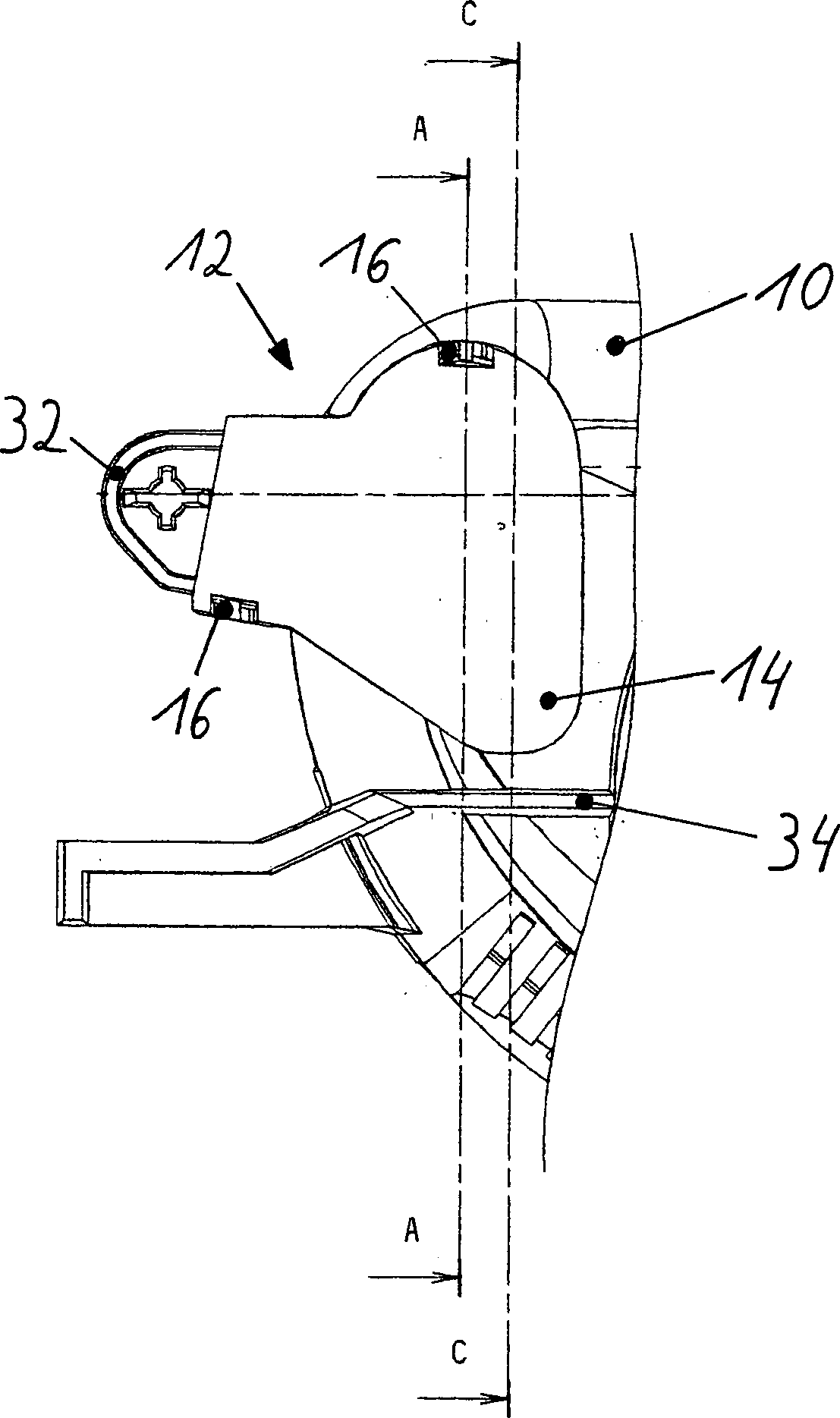
Belüftungssystem (12) einer Leuchte, insbesondere eines Scheinwerfers für Fahrzeuge, weiches an einem Leuchtengehäuse (10) angebracht ist, das zur Aufnahme einer Lichtquelle dient und auf seiner Vorderseite durch eine lichtdurchlässige Abschlussscheibe abgeschlossen ist, mit zumindest einem an das Leuchtengehäuse angeformten labyrinthartigen Belüftungsdurchgang (18) zum Inneren der Leuchte, dadurch gekennzeichnet, dass der labyrinthartige Belüftungsdurchgang (18) mit einer zweiten Belüftungsanordnung (42) in Wirkverbindung steht, wobei die zweite Belüftungsanordnung (42) den Belüftungsdurchgang (18) umschließt und durch eine Kappe (14) und durch seitlich von dem labyrinthartigen Belüftungsdurchgang (18) angeordnete Wände (24, 26, 28, 30) gebildet wird, wobei sich die Wände (28, 30) im wesentlichen parallel der Längsachse des Belüftungsdurchgangs (18) erstrecken, den Belüftungsdurchgang (18) in seiner axialen Ausdehnung überragen und der durch die Wände (24, 26, 28, 30) erzeugte Raum (20) zumindest bereichsweise von der Kappe (14) derart abgedeckt ist, dass die zweite Belüftungsanordnung (42) zumindest eine Öffnung (38) aufweist.ventilation system (12) a lamp, in particular a headlamp for vehicles, soft on a luminaire housing (10) is mounted, which serves to receive a light source and completed on its front by a translucent lens is, with at least one of the lamp housing molded labyrinthine Ventilation passage (18) to the interior of the lamp, characterized in that the labyrinthine Ventilation passage (18) with a second ventilation arrangement (42) is in operative connection, wherein the second ventilation arrangement (42) the ventilation passage (18) encloses and through a cap (14) and laterally from the labyrinthine Ventilation passage (18) arranged walls (24, 26, 28, 30) is formed, wherein the walls (28, 30) substantially parallel to the longitudinal axis the ventilation passage (18) extend the ventilation passage (18) protrude in its axial extent and by the Walls (24, 26, 28, 30) generated space (20) at least partially from the cap (14) is covered such that the second ventilation arrangement (42) at least an opening (38) having.
Description
Die Erfindung betrifft ein Belüftungssystem einer Leuchte, insbesondere eines Scheinwerfers für Fahrzeuge, welches an einem Gehäuse angebracht ist, das zur Aufnahme einer Lichtquelle dient und auf seiner Vorderseite durch eine lichtdurchlässige Abschlussscheibe abgeschlossen ist, mit zumindest einem an das Gehäuse angeformten labyrinthartigen Belüftungsdurchgang zum Inneren der Leuchte.The The invention relates to a ventilation system of a Luminaire, in particular a headlight for vehicles, which at a casing attached, which serves to receive a light source and on his Front completed by a translucent lens is, with at least one molded to the housing labyrinth ventilation passage to the interior of the lamp.
In
der
Aus
der
Aus
der
Aus
der
Aus
der
Das
deutsche Gebrauchsmuster
Aufgabe der Erfindung ist es, das bekannte Belüftungssystem einer Leuchte, insbesondere eines Scheinwerfers für Fahrzeuge, derart zu verbessern, dass auch bei plötzlich auftretenden großen Wassermengen kein Wasser und keine Aerosole in das Innere der Leuchte eindringen können.The object of the invention is the known ventilation system of a lamp, in particular a Headlights for vehicles, to improve so that even with suddenly occurring large amounts of water no water and no aerosols can penetrate into the interior of the lamp.
Diese Aufgabe wird erfindungsgemäß dadurch gelöst, dass der labyrinthartige Belüftungsdurchgang mit einer zweiten Belüftungsanordnung in Wirkverbindung steht, wobei die zweite Belüftungsanordnung den Belüftungsdurchgang umschließt und durch eine Kappe und durch seitlich von dem labyrinthartigen Belüftungsdurchgang angeordneten Wände gebildet wird, wobei sich die Wände im wesentlichen parallel der Längsachse des Belüftungsdurchgangs erstrecken, den Belüftungsdurchgang in seiner axialen Ausdehnung überragen und der durch die Wände erzeugte Raum zumindest bereichsweise von der Kappe derart abgedeckt ist, dass die zweite Belüftungsöffnung zumindest eine Öffnung aufweist.These Task is inventively characterized solved, that the labyrinth-like ventilation passage with a second ventilation arrangement is operatively connected, wherein the second ventilation arrangement the ventilation passage surrounds and by a cap and by the side of the labyrinthine Ventilation passage arranged walls is formed, with the walls substantially parallel to the longitudinal axis the ventilation passage extend the ventilation passage project beyond its axial extent and through the walls generated space at least partially covered by the cap so is that the second vent at least an opening having.
Vorteilhaft an einem derartigen Belüftungssystem ist es, dass durch die zweite Belüftungsanordnung das bekannte Belüftungssystem gegen das Eindringen von Wasser geschützt wird. Der Luftstrom beruhigt sich in dem durch die zweite Belüftungsanordnung erzeugten Raum, so dass sich Wasser und die in der Luft befindlichen Aerosole absetzten und nicht in den Leuchteninnenraum gelangen. Somit wird nur saubere, feuchte Luft durch den labyrinthartigen Belüftungsdurchgang in den Leuchteninnenraum angesaugt und damit z. B. ein Beschlagen der Abschlussscheibe vermieden.Advantageous on such a ventilation system it is that through the second ventilation arrangement, the known ventilation system is protected against the ingress of water. The air flow calms down in the second ventilation arrangement generated space, leaving water and those in the air Store aerosols and do not enter the interior of the lamp. Thus, only clean, moist air through the labyrinthine Ventilation passage sucked into the lamp interior and thus z. B. fogging the lens is avoided.
Eine derartige Anordnung der zweiten Belüftungsanordnung an dem Leuchtengehäuse ermöglicht es, dass das Belüftungssystem trotz seines großen Bauraumvolumens sehr klein- und flachbauend an der Rückseite des Leuchtengehäuses angeordnet ist.A Such arrangement of the second ventilation arrangement on the luminaire housing makes it possible to that the ventilation system despite his great Volume of construction very small and flat at the back of the luminaire housing is arranged.
Es ist vorteilhaft, dass die zweite Belüftungsanordnung ein im Verhältnis zu dem Belüftungsdurchgang großes Bauraumvolumen hat, damit sich die einströmende Luft in der zweiten Belüftungsanordnung ausreichend beruhigen kann.It is advantageous that the second ventilation arrangement in relation to the ventilation passage great Space has volume, so that the incoming air in the second ventilation arrangement sufficiently calm.
Damit eine ausreichende Belüftung des erzeugten Raumes und somit auch des Leuchteninnenraumes gewährleistet ist, weist die zweite Belüftungsanordnung zumindest eine Öffnung, zweckmäßigerweise zwei oder mehr Öffnungen auf, die ein störungsfreies Durchströmen des Raumes ermöglichen.In order to adequate ventilation the generated space and thus also the lighting interior ensured is, has the second ventilation arrangement at least one opening, expediently two or more openings on that a trouble-free Flow through of the room.
Bei einer vorteilhaften Ausführungsform der Erfindung ist zumindest eine Öffnung im in Einbaulage der Leuchte tiefsten Punkt der zweiten Belüftungsanordnung, damit das in den Raum eindringende Wasser abläuft und die aus der Luft sich absetzenden Aerosole aus dem Raum ausströmen.at an advantageous embodiment the invention is at least one opening in the installed position of the Luminaire lowest point of the second ventilation arrangement, so that the Water entering the room drains out of the air pouring aerosols out of the room.
Weiterhin ist es vorteilhaft, die zumindest eine Öffnung in der zweiten Belüftungsanordnung durch zusätzliche Wände gegen das Eindringen von die Leuchte umströmenden Spritzwasser zu schützen.Farther it is advantageous, the at least one opening in the second ventilation arrangement by additional Walls against to protect the penetration of spray around the luminaire.
Sollte doch einmal Wasser in die zweite Belüftungsanordnung eindringen, ist es vorteilhaft, dass die Wände der zweiten Belüftungsanordnung so angeordnet sind, dass sie in Einbaulage der Leuchte zumindest im unteren Bereich der zweiten Belüftungsanordnung nicht waagerecht verlaufen. Zweckmäßigerweise läuft zumindest eine Wand trichterförmig in Richtung des vertikal tiefsten Punktes zu, damit das Wasser nicht in der zweiten Belüftungsanordnung steht und sofort durch die im tiefsten Punkt angeordnete Öffnung abläuft.Should but once water penetrate into the second ventilation arrangement, It is beneficial that the walls the second ventilation arrangement are arranged so that they at least in the installation position of the lamp not horizontal in the lower area of the second ventilation arrangement run. Conveniently, at least runs a wall funnel-shaped towards the vertical lowest point, so that the water does not in the second ventilation arrangement stands and runs immediately through the opening arranged in the lowest point.
Um den erzeugten Raum und/oder den labyrinthartigen Belüftungsdurchgang gegebenenfalls zu reinigen, ist die Kappe lösbar, vorteilhafterweise mittels einer Rastverbindung, mit den Wänden verbunden.Around the generated space and / or the labyrinth-like ventilation passage if necessary to clean, the cap is detachable, advantageously by means of a locking connection, with the walls connected.
Der Fertigungs- und Materialaufwand der Leuchte kann minimiert werden, indem die Wände an das Leuchtengehäuse angeformt sind und/oder zumindest teilweise durch das Leuchtengehäuse gebildet werden.Of the Manufacturing and material costs of the luminaire can be minimized by the walls to the luminaire housing are formed and / or at least partially formed by the lamp housing become.
Nachfolgend ist ein vorteilhaftes Ausführungsbeispiel der Erfindung anhand der Zeichnungen näher erläutert. Es zeigen:following is an advantageous embodiment the invention explained in more detail with reference to the drawings. Show it:
Ein
Belüftungssystem
(
Bei
einer andersartigen, nicht dargestellten Ausführungsform der Erfindung ist
die Kappe (
Die
Funktionsweise des Belüftungssystems (
- 1010
- Leuchtengehäuseluminaire housing
- 1212
- Belüftungssystemventilation system
- 1414
- Kappecap
- 1616
- Rastverbindunglocking connection
- 1818
- labyrinthartiger Belüftungsdurchganglabyrinthine Ventilation passage
- 2020
- Raumroom
- 2222
- LeuchteninnenraumLights Interior
- 2424
- Wandwall
- 2626
- Wandwall
- 2828
- Wandwall
- 3030
- Wandwall
- 3232
- Wandwall
- 3434
- Wandwall
- 3636
- obere Öffnungupper opening
- 3838
- untere Öffnunglower opening
- 4040
- Ablaufprocedure
- 4242
- zweite Belüftungsanordnungsecond ventilation arrangement
Claims (10)
Priority Applications (2)
| Application Number | Priority Date | Filing Date | Title |
|---|---|---|---|
| DE10055152A DE10055152B4 (en) | 2000-11-07 | 2000-11-07 | Ventilation system of a lamp, in particular a headlight for vehicles |
| EP01125955A EP1205706A3 (en) | 2000-11-07 | 2001-10-31 | Ventilation system for a lamp, in particular for vehicle headlamps |
Applications Claiming Priority (1)
| Application Number | Priority Date | Filing Date | Title |
|---|---|---|---|
| DE10055152A DE10055152B4 (en) | 2000-11-07 | 2000-11-07 | Ventilation system of a lamp, in particular a headlight for vehicles |
Publications (2)
| Publication Number | Publication Date |
|---|---|
| DE10055152A1 DE10055152A1 (en) | 2002-05-08 |
| DE10055152B4 true DE10055152B4 (en) | 2009-05-14 |
Family
ID=7662438
Family Applications (1)
| Application Number | Title | Priority Date | Filing Date |
|---|---|---|---|
| DE10055152A Expired - Fee Related DE10055152B4 (en) | 2000-11-07 | 2000-11-07 | Ventilation system of a lamp, in particular a headlight for vehicles |
Country Status (2)
| Country | Link |
|---|---|
| EP (1) | EP1205706A3 (en) |
| DE (1) | DE10055152B4 (en) |
Families Citing this family (3)
| Publication number | Priority date | Publication date | Assignee | Title |
|---|---|---|---|---|
| DE102004006078B4 (en) * | 2004-02-07 | 2014-04-30 | Hella Kgaa Hueck & Co. | Cover lens for headlight and coating device |
| DE102014106502A1 (en) | 2014-05-08 | 2015-11-12 | AZ Ausrüstung und Zubehör GmbH & Co. KG | Ventilation system for vehicle lighting |
| US10281107B1 (en) * | 2018-06-26 | 2019-05-07 | GM Global Technology Operations LLC | Cap assembly and vent body for a light housing on a vehicle |
Citations (8)
| Publication number | Priority date | Publication date | Assignee | Title |
|---|---|---|---|---|
| DE2346643A1 (en) * | 1973-09-17 | 1975-03-27 | Westfaelische Metall Industrie | Motor vehicle cooled headlamp - has absorbent for air passing through with throttles before and after |
| DE3319411C2 (en) * | 1983-05-28 | 1986-08-07 | Westfälische Metall Industrie KG Hueck & Co, 4780 Lippstadt | Vehicle headlights |
| EP0234335A2 (en) * | 1986-02-14 | 1987-09-02 | NORKA Norddeutsche Kunststoff- und Elektro-Gesellschaft Stäcker & Co. mbH | Light fitting |
| FR2710398A1 (en) * | 1993-09-21 | 1995-03-31 | Valeo Vision | Chicane ventilation device for a lighting or signalling device for a motor vehicle |
| FR2710397A1 (en) * | 1993-09-21 | 1995-03-31 | Valeo Vision | Labyrinth ventilation device and system for ventilating a lighting or signalling device for a motor vehicle |
| DE69301998T2 (en) * | 1992-11-09 | 1996-08-08 | Valeo Vision | Motor vehicle lighting or signaling device with improved ventilation system |
| DE69303512T2 (en) * | 1992-02-17 | 1997-01-30 | Valeo Vision | Headlights with an improved ventilation device, in particular for motor vehicles |
| DE29622618U1 (en) * | 1992-05-20 | 1997-03-13 | Valeo Vision, Bobigny | Headlights with improved ventilation device, in particular for motor vehicles |
Family Cites Families (5)
| Publication number | Priority date | Publication date | Assignee | Title |
|---|---|---|---|---|
| JPH02145704U (en) | 1989-05-15 | 1990-12-11 | ||
| DE9402383U1 (en) * | 1994-02-14 | 1994-03-31 | Hella KG Hueck & Co., 59557 Lippstadt | Ventilation system for a lamp, in particular a headlight for vehicles |
| JP2813858B2 (en) * | 1994-03-01 | 1998-10-22 | 株式会社小糸製作所 | Vehicle lighting |
| US5497308A (en) * | 1994-05-09 | 1996-03-05 | Koito Manufacturing Co., Ltd. | Vehicular lamp |
| US5823378A (en) * | 1997-03-27 | 1998-10-20 | Gseg Llc | Breather vent for electrical enclosure |
-
2000
- 2000-11-07 DE DE10055152A patent/DE10055152B4/en not_active Expired - Fee Related
-
2001
- 2001-10-31 EP EP01125955A patent/EP1205706A3/en not_active Withdrawn
Patent Citations (8)
| Publication number | Priority date | Publication date | Assignee | Title |
|---|---|---|---|---|
| DE2346643A1 (en) * | 1973-09-17 | 1975-03-27 | Westfaelische Metall Industrie | Motor vehicle cooled headlamp - has absorbent for air passing through with throttles before and after |
| DE3319411C2 (en) * | 1983-05-28 | 1986-08-07 | Westfälische Metall Industrie KG Hueck & Co, 4780 Lippstadt | Vehicle headlights |
| EP0234335A2 (en) * | 1986-02-14 | 1987-09-02 | NORKA Norddeutsche Kunststoff- und Elektro-Gesellschaft Stäcker & Co. mbH | Light fitting |
| DE69303512T2 (en) * | 1992-02-17 | 1997-01-30 | Valeo Vision | Headlights with an improved ventilation device, in particular for motor vehicles |
| DE29622618U1 (en) * | 1992-05-20 | 1997-03-13 | Valeo Vision, Bobigny | Headlights with improved ventilation device, in particular for motor vehicles |
| DE69301998T2 (en) * | 1992-11-09 | 1996-08-08 | Valeo Vision | Motor vehicle lighting or signaling device with improved ventilation system |
| FR2710398A1 (en) * | 1993-09-21 | 1995-03-31 | Valeo Vision | Chicane ventilation device for a lighting or signalling device for a motor vehicle |
| FR2710397A1 (en) * | 1993-09-21 | 1995-03-31 | Valeo Vision | Labyrinth ventilation device and system for ventilating a lighting or signalling device for a motor vehicle |
Also Published As
| Publication number | Publication date |
|---|---|
| EP1205706A2 (en) | 2002-05-15 |
| EP1205706A3 (en) | 2004-10-13 |
| DE10055152A1 (en) | 2002-05-08 |
Similar Documents
| Publication | Publication Date | Title |
|---|---|---|
| DE19811189C1 (en) | Automobile body with electrical auxiliaries separated from engine compartment | |
| DE3138360C2 (en) | Vehicle headlights with forced internal ventilation | |
| DE4303663C1 (en) | Water separation fresh air intake for vehicle - has water collection chambers and air path with flow reversal. | |
| EP3283353B1 (en) | Windshield cover arrangement for a motor vehicle | |
| DE2641444C2 (en) | Assembly room for motor vehicles | |
| DE3512882C2 (en) | ||
| DE102014112535B4 (en) | Motor vehicle air conditioning system with detachably connected filter cover | |
| DE10055152B4 (en) | Ventilation system of a lamp, in particular a headlight for vehicles | |
| DE3220704C2 (en) | Device for ventilation of the interior of headlights for motor vehicles | |
| DE3336003A1 (en) | VENTILATION DEVICE FOR MOTOR VEHICLES | |
| DE10355900B3 (en) | Building lighting device secured in rain gutter via integral spring arms of fixing clips for lamp housing | |
| DE3048969A1 (en) | HEADLIGHTS FOR MOTOR VEHICLES | |
| DE3300383C2 (en) | Vehicle light | |
| DE3044407A1 (en) | HEADLIGHTS, ESPECIALLY FOR MOTOR VEHICLES | |
| DE3424205C2 (en) | Vehicle light | |
| DE3213985C2 (en) | Motor vehicle light | |
| DE69310266T2 (en) | Headlights with improved ventilation device, in particular for motor vehicles | |
| DE3007326C2 (en) | ||
| DE3004225C2 (en) | Extractor hood for exhaust air operation with a hose-like air guiding device | |
| DE102005003480B4 (en) | Lighting device for a vehicle with means for preventing condensation | |
| DE9402383U1 (en) | Ventilation system for a lamp, in particular a headlight for vehicles | |
| DE19522669C2 (en) | Housing of a light-generating device for motor vehicles | |
| DE69301998T2 (en) | Motor vehicle lighting or signaling device with improved ventilation system | |
| DE102014105389B4 (en) | Arrangement for ventilating a headlight of a motor vehicle | |
| DE10012248A1 (en) | Motor vehicle headlamp has frame enclosing ventilation channel at distance, inclined in same direction as ventilation channel at lower edge, with least one opening near lowest point |
Legal Events
| Date | Code | Title | Description |
|---|---|---|---|
| OM8 | Search report available as to paragraph 43 lit. 1 sentence 1 patent law | ||
| 8127 | New person/name/address of the applicant |
Owner name: HELLA KGAA HUECK & CO., 59557 LIPPSTADT, DE |
|
| 8110 | Request for examination paragraph 44 | ||
| 8364 | No opposition during term of opposition | ||
| R081 | Change of applicant/patentee |
Owner name: HELLA GMBH & CO. KGAA, DE Free format text: FORMER OWNER: HELLA KGAA HUECK & CO., 59557 LIPPSTADT, DE |
|
| R084 | Declaration of willingness to licence | ||
| R119 | Application deemed withdrawn, or ip right lapsed, due to non-payment of renewal fee |