CN203542031U - Brake disc straight-line-shaped automatic machining production line - Google Patents
Brake disc straight-line-shaped automatic machining production line Download PDFInfo
- Publication number
- CN203542031U CN203542031U CN201320715815.9U CN201320715815U CN203542031U CN 203542031 U CN203542031 U CN 203542031U CN 201320715815 U CN201320715815 U CN 201320715815U CN 203542031 U CN203542031 U CN 203542031U
- Authority
- CN
- China
- Prior art keywords
- numerical control
- brake disc
- order
- manipulator
- control vertical
- Prior art date
- Legal status (The legal status is an assumption and is not a legal conclusion. Google has not performed a legal analysis and makes no representation as to the accuracy of the status listed.)
- Expired - Fee Related
Links
- 238000003754 machining Methods 0.000 title claims abstract description 32
- 238000004519 manufacturing process Methods 0.000 title claims abstract description 25
- 238000007514 turning Methods 0.000 claims abstract description 15
- 238000007599 discharging Methods 0.000 abstract 3
- 238000012545 processing Methods 0.000 description 14
- 238000000034 method Methods 0.000 description 7
- 239000000463 material Substances 0.000 description 5
- 230000009286 beneficial effect Effects 0.000 description 1
- 230000007423 decrease Effects 0.000 description 1
- 238000005516 engineering process Methods 0.000 description 1
- 238000009472 formulation Methods 0.000 description 1
- 238000003801 milling Methods 0.000 description 1
- 239000000203 mixture Substances 0.000 description 1
Images
Landscapes
- Multi-Process Working Machines And Systems (AREA)
Abstract
The utility model discloses a bake disc straight-line-shaped automatic machining production line which comprises a feeding roller way and a discharging roller way. A first-order numerical control vertical lathe, a second-order numerical control vertical lathe and a third-order vertical machining center are arranged in sequence between the feeding roller way and the discharging roller way. The bake disc straight-line-shaped automatic machining production line is characterized in that crank arm mechanical arms are arranged between the feeding roller way and the first-order numerical control vertical lathe, between the first-order numerical control vertical lathe and the second-order numerical control vertical lathe, between the second-order numerical control vertical lath and the third-order vertical machining center and between the third-order vertical machining center and the discharging roller way, and workbenches of two crank arm mechanical arms in the middle are provided with a first workpiece turning unit and a second turning unit which can achieve brake disc turning. According to the bake disc straight-line-shaped automatic machining production line, automation of the whole machining process of the brake disc is achieved, workers are of no need, labor intensity and cost are lowered, machining efficiency is improved, and the quality of machined workpieces is guaranteed.
Description
Technical field
The utility model relates to a kind of brake disc linear automatic production line, in particular, relate in particular to a kind of workpiece loading and unloading, capture, transport, place and process the brake disc linear automatic production line all completing by machine automatization.
Background technology
Domestic automobile parts machining industry size is larger at present, but most enterprises still adopts more traditional technological process, and manual operation numerical control device is produced.Along with the continuous increase of domestic human cost, business burden is more and more heavier.Meanwhile, due to factors such as peopleware, quantity, not only can not guarantee born product quality, and the management expectancy of enterprise and cost are improved constantly.
The patent No. is the utility model patent file of CN201120069366.6, a kind of linear production line of brake disk is disclosed, it is by 4 numerical control vertical lathes, 1 machining center, 1 balance detector, 1 balance Milling Machine, 1 automatic detecting machine and 1 carving machine form, due to the device that brake disc is transmitted automatically not being set, and do not have setting can carry out to brake disc the manipulator of automatic capturing and placement, therefore it is still operated and is realized processing by several staff, this linear production line, not only production cost is high, labour intensity is large, but also can not guarantee to process the uniformity of workpiece quality.
Summary of the invention
The utility model, in order to overcome the shortcoming of above-mentioned technical problem, provides a kind of brake disc linear automatic production line.
Brake disc linear automatic production line of the present utility model, comprise the charging roller and the blanking roller-way that transport respectively brake disc blank and finished product, charging roller is to being disposed with an order numerical control vertical lathe, two order numerical control vertical lathes and three order vertical machining centres between blanking track, one order numerical control vertical lathe is processed it by a surface of brake disc, and two order numerical control vertical lathes are processed it by another surface of brake disc; Its special feature is: between charging roller and an order numerical control vertical lathe, between an order numerical control vertical lathe and two order numerical control vertical lathes, between two order numerical control vertical lathes and three order vertical machining centres and be respectively arranged with first manipulator, second manipulator, the 3rd manipulator, the 4th manipulator of cranking arm of cranking arm of cranking arm of cranking arm that can brake disc be picked and placeed and be carried between three order vertical machining centres and blanking roller-way; Described second manipulator, the 3rd of cranking arm is cranked arm on the workbench of manipulator and is respectively arranged with the first workpiece turning unit and the second roll-over unit that can realize brake disc upset.
Charging roller is transported to feeding station by blank to be processed, and first manipulator of cranking arm is transported to an order numerical control vertical lathe by brake disc blank, and second manipulator of cranking arm is transported to two order numerical control vertical lathes by processing brake disc.Through the complete brake disc workpiece of two order numerical control vertical Vehicle Processings, through the 3rd Manipulator Transportation to the three order vertical machining centre of cranking arm, after three order vertical machining centres processing, complete the processing of brake disc workpiece, the 4th manipulator of cranking arm is taken to the brake disc workpiece of completion of processing.
Brake disc linear automatic production line of the present utility model, between described charging roller and the first conveying robot, be provided with for brake disc being moved away to the first conveying robot of charging roller, the 4th cranks arm is provided with and uses the second conveying robot of brake disc being moved into blanking roller-way between manipulator and blanking roller-way.
Brake disc linear automatic production line of the present utility model, is provided with for loading the cutter tower of cutter on a described order numerical control vertical lathe and two order numerical control vertical lathes, and on cutter tower, being provided with can be to machined part and the two secondary handgrips that workpiece captures simultaneously; In three order vertical machining centres, being provided with can be to machined part and two handgrip fixtures that workpiece captures.
The beneficial effects of the utility model are: brake disc linear automatic production line of the present utility model, by at charging roller to setting gradually first manipulator of cranking arm between blanking roller-way, one order numerical control vertical lathe, second manipulator of cranking arm, two order numerical control vertical lathes, the 3rd manipulator of cranking arm, three order vertical machining centres, the 4th manipulator of cranking arm, not only realized the automatic loading/unloading of brake disc workpiece, and realized the crawl of brake disc workpiece between each manufacturing procedure by the manipulator of cranking arm, transport and place, realized the automation of the whole process of brake disc, saved staff's participation, labour intensity and cost have been reduced, working (machining) efficiency is provided, guaranteed to process the quality of workpiece.
Second manipulator and the 3rd manipulator place of cranking arm of cranking arm is provided with workpiece turning unit, can realize the positive and negative upset of brake disc workpiece, can to it, process by the different surfaces of brake disc.At charging roller, blanking roller-way place, be provided with conveying robot, can effectively brake disc workpiece be moved away to charging roller and move into blanking roller-way.
This novel described orthoscopic automatic machining line is by being equipped with polymorphic type manipulator, and the whole processing link of brake disc, without artificial participation, has saved artificial and management cost.The employing of automatic flow, has also guaranteed the uniformity of workpiece crudy to have improved production efficiency, is also convenient to formulation and the production management of enterprise's production schedule simultaneously.
Accompanying drawing explanation
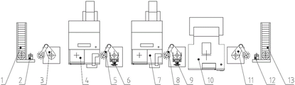
Fig. 1 is the structural representation of brake disc linear automatic production line of the present utility model.
In figure: 1 charging roller, 2 first conveying robots, 3 first manipulators of cranking arm, 4 one order numerical control vertical lathes, 5 second manipulators of cranking arm, 6 first workpiece turning unit, 7 two order numerical control vertical lathes, 8 the 3rd manipulators of cranking arm, 9 second roll-over units, 10 3 order vertical machining centres, 11 the 4th manipulators of cranking arm, 12 second conveying robots, 13 blanking roller-ways.
The specific embodiment
Below in conjunction with accompanying drawing and embodiment, the utility model is described in further detail.
As shown in Figure 1, provided the structural representation of brake disc linear automatic production line of the present utility model, it comprises charging roller 1, blanking roller-way 13 and is set in turn in charging roller 1 to first between blanking roller-way 13 crank arm manipulator 3, an order numerical control vertical lathe 4, second crank arm manipulator 5, two order numerical control vertical lathes the 7, the 3rd crank arm manipulator 8, three order vertical machining centres 10.Second cranks arm is provided with the first workpiece turning unit 6, the three on manipulator 5 and cranks arm on manipulator 8 and be provided with second workpiece roll-over unit 9.Charging roller 1 and first is cranked arm and is provided with between the first conveying robot 2, three order vertical machining centres 10 and blanking roller-way 13 and is provided with the second conveying robot 12 between manipulator 3.
Charging roller 1 is for being transported to upper material level by brake disc blank, the first conveying robot 2 is moved away from brake disc blank from charging roller 1, first manipulator 3 grabbing workpiece putting it in an order numerical control vertical lathe 4 from the first conveying robot 2 of cranking arm, by brake disc blank one processes in the face of it an order numerical control vertical lathe 4.The second workpiece of cranking arm after manipulator 5 crawl one order numerical control vertical lathe 4 processing, put it in the first workpiece turning unit 6 and overturn, and the workpiece capturing after upset is put in two order numerical control vertical lathes 7, two order numerical control vertical lathes 7 are processed in the face of it by another of brake disc workpiece.The 3rd crank arm manipulator 8 captures the workpiece after two order numerical control vertical lathes 7 processing and puts it in the second roll-over unit 9 and overturns, then, the 3rd crank arm manipulator 8 by upset after brake disc put in three order vertical machining centres 10, by three order vertical machining centres 10, complete the last processing to brake disc workpiece.The 4th manipulator 11 of cranking arm takes off the workpiece after three order vertical machining centres 10 processing be put on the second conveying robot 12, and the second conveying robot 12 is moved into brake disc workpiece in blanking roller-way 13 again, by blanking roller-way 13, the workpiece of completion of processing is transported.
One order numerical control vertical lathe 4 is in order to coordinate first manipulator 3 of cranking arm to put into workpiece and second manipulator 5 grabbing workpieces of cranking arm, on the cutter tower of one order numerical control vertical lathe 4, be mounted with two secondary handgrips, one secondary handgrip is for capturing first workpiece to be processed on manipulator 3 of cranking arm, and another secondary handgrip is used for capturing finished work.Similarly, two order numerical control vertical lathes 7, in order to coordinate second manipulator 5 of cranking arm to put into workpiece and the 3rd manipulator 8 grabbing workpieces of cranking arm, are also provided with two secondary handgrips on its cutter tower.Three order vertical machining centres for simultaneously to machined part and workpiece capture, on it, be provided with two handgrip fixtures.
The course of work of brake disc linear automatic production line of the present utility model is as follows:
During work, blank is delivered to upper material level through charging roller 1, and first manipulator 3 of cranking arm is prepared to connect material near extending to charging roller 1.The first conveying robot 2 captures brake disc blanks and moves to first manipulator 3 tops of cranking arm and put down workpiece, and the first conveying robot 2 is return.First manipulator 3 of cranking arm carries workpiece and rotates into an order numerical control vertical lathe 4, and second manipulator 5 of cranking arm stretches into and prepares to connect material from order numerical control vertical lathe 4 opposite sides simultaneously.The cutter tower of one order numerical control vertical lathe 4 is provided with 2 secondary handgrips, cutter tower moves down, one secondary handgrip captures the first blank of cranking arm on manipulator 3, another secondary handgrip captures finished work, cutter tower moves horizontally, and blank is put into chuck, workpiece is put into second simultaneously and cranks arm on manipulator 5, first, second manipulator of cranking arm exits lathe, and an order numerical control vertical lathe 4 starts processing.Second manipulator 5 of cranking arm carries workpiece rotation to 6 belows, the first workpiece turning unit, and the paw decline certain altitude grabbing workpiece on the first workpiece turning unit 6 rises also and overturn 180 °, realizes after workpiece turning, and paw unclamps workpiece.Second manipulator 5 grabbing workpiece from the first workpiece turning unit 6 of cranking arm, carry workpiece and rotate into two order numerical control vertical lathes 7, two order numerical control vertical lathes 7 adopt the mode identical with an order numerical control vertical lathe 4, and the second to be processed of cranking arm on manipulator 5 put into chuck and workpiece put into the 3rd and crank arm on manipulator 8.
The 3rd manipulator 8 of cranking arm carries workpiece and rotates to second workpiece roll-over unit 9 belows, second workpiece roll-over unit 9 adopts the mode communicating with the first workpiece turning unit 6 by 180 ° of workpiece turnings, complete after upset, the 3rd manipulator 8 of cranking arm carries workpiece and rotates into three order vertical machining centres 10, and the 4th manipulator 11 of cranking arm stretches into and prepares to connect material from three order vertical machining centre 10 opposite sides simultaneously.The main axle moving of three order machining centers 10 two handgrip fixtures that change the outfit, capture simultaneously to be processed and workpiece to complete workpiece loading and unloading.Three, the 4th manipulator of cranking arm exits three order vertical machining centres 10, completes after loading and unloading, and the three order vertical machining centre 10 main shafts cutter that again changes the outfit, starts processing.The 4th manipulator 11 of cranking arm carries workpiece rotation to the second conveying robot 12 belows, and the second conveying robot 12 grabbing workpieces move to blanking roller-way 13, complete blanking.
Claims (3)
1. a brake disc linear automatic production line, comprise the charging roller (1) and the blanking roller-way (13) that transport respectively brake disc blank and finished product, charging roller is to being disposed with an order numerical control vertical lathe (4), two order numerical control vertical lathes (7) and three order vertical machining centres (10) between blanking track, one order numerical control vertical lathe is processed it by a surface of brake disc, and two order numerical control vertical lathes are processed it by another surface of brake disc; It is characterized in that: between charging roller and an order numerical control vertical lathe, between an order numerical control vertical lathe and two order numerical control vertical lathes, between two order numerical control vertical lathes and three order vertical machining centres and be respectively arranged with first manipulator (3), second manipulator (5), the 3rd manipulator (6), the 4th manipulator (11) of cranking arm of cranking arm of cranking arm of cranking arm that can brake disc be picked and placeed and be carried between three order vertical machining centres and blanking roller-way; Described second manipulator (5), the 3rd of cranking arm is cranked arm on the workbench of manipulator (8) and is respectively arranged with the first workpiece turning unit (6) and the second roll-over unit (9) that can realize brake disc upset.
2. brake disc linear automatic production line according to claim 1, it is characterized in that: between described charging roller (1) and the first conveying robot (2), be provided with for brake disc being moved away to first conveying robot (2) of charging roller, the 4th cranks arm is provided with and uses the second conveying robot (12) of brake disc being moved into blanking roller-way between manipulator (11) and blanking roller-way (13).
3. brake disc linear automatic production line according to claim 1, it is characterized in that: on a described order numerical control vertical lathe (4) and two order numerical control vertical lathes (7), be provided with for loading the cutter tower of cutter, on cutter tower, being provided with can be to machined part and the two secondary handgrips that workpiece captures simultaneously; In three order vertical machining centres (10), being provided with can be to machined part and two handgrip fixtures that workpiece captures.
Priority Applications (1)
| Application Number | Priority Date | Filing Date | Title |
|---|---|---|---|
| CN201320715815.9U CN203542031U (en) | 2013-11-14 | 2013-11-14 | Brake disc straight-line-shaped automatic machining production line |
Applications Claiming Priority (1)
| Application Number | Priority Date | Filing Date | Title |
|---|---|---|---|
| CN201320715815.9U CN203542031U (en) | 2013-11-14 | 2013-11-14 | Brake disc straight-line-shaped automatic machining production line |
Publications (1)
| Publication Number | Publication Date |
|---|---|
| CN203542031U true CN203542031U (en) | 2014-04-16 |
Family
ID=50460199
Family Applications (1)
| Application Number | Title | Priority Date | Filing Date |
|---|---|---|---|
| CN201320715815.9U Expired - Fee Related CN203542031U (en) | 2013-11-14 | 2013-11-14 | Brake disc straight-line-shaped automatic machining production line |
Country Status (1)
| Country | Link |
|---|---|
| CN (1) | CN203542031U (en) |
Cited By (15)
| Publication number | Priority date | Publication date | Assignee | Title |
|---|---|---|---|---|
| CN104476201A (en) * | 2014-12-05 | 2015-04-01 | 黄山菲英汽车零部件有限公司 | Brake pad processing production line |
| CN104476200A (en) * | 2014-12-05 | 2015-04-01 | 黄山菲英汽车零部件有限公司 | Automotive brake pad production line |
| CN104493494A (en) * | 2014-12-05 | 2015-04-08 | 黄山菲英汽车零部件有限公司 | Drum brake piece forming processing production line |
| CN105236135A (en) * | 2015-11-11 | 2016-01-13 | 万达工业(始兴)有限公司 | Automatic pad printing production line |
| CN106406248A (en) * | 2015-08-04 | 2017-02-15 | 刘巍巍 | Brake-disc digital automatic production line control communication protocol |
| CN106891169A (en) * | 2017-04-01 | 2017-06-27 | 浙江工业职业技术学院 | A kind of brake disc automatic production line |
| CN107052809A (en) * | 2017-04-01 | 2017-08-18 | 浙江工业职业技术学院 | A kind of equipment for manufacturing venting plate |
| CN108568692A (en) * | 2017-12-05 | 2018-09-25 | 湖南飞沃新能源科技股份有限公司 | Machine-position loading and unloading equipment |
| CN108584339A (en) * | 2018-04-02 | 2018-09-28 | 曾袁 | A kind of titanium-base alloy automobile brake disc processing unit (plant) |
| CN110153726A (en) * | 2019-05-16 | 2019-08-23 | 广东扬山联合精密制造股份有限公司 | The automatic production line of compressor of air conditioner roller |
| CN110405103A (en) * | 2019-08-05 | 2019-11-05 | 浙江凌宇机械股份有限公司 | A kind of brake disc production line |
| CN110480401A (en) * | 2019-08-28 | 2019-11-22 | 安徽好运机械有限公司 | A kind of flexible automation processing unit for fork truck gantry mounting support seat processing |
| CN112108858A (en) * | 2020-09-02 | 2020-12-22 | 东风本田汽车零部件有限公司 | Equipment for screwing and unscrewing screw and nut of automobile brake disc |
| CN113814421A (en) * | 2020-06-21 | 2021-12-21 | 苏州伯恩特机械科技有限公司 | Pressure disc machining system and method |
| CN115502730A (en) * | 2022-09-29 | 2022-12-23 | 湖南华煜恒远企业管理合伙企业(有限合伙) | Automatic production line for motor brake groove discs |
-
2013
- 2013-11-14 CN CN201320715815.9U patent/CN203542031U/en not_active Expired - Fee Related
Cited By (19)
| Publication number | Priority date | Publication date | Assignee | Title |
|---|---|---|---|---|
| CN104476201A (en) * | 2014-12-05 | 2015-04-01 | 黄山菲英汽车零部件有限公司 | Brake pad processing production line |
| CN104476200A (en) * | 2014-12-05 | 2015-04-01 | 黄山菲英汽车零部件有限公司 | Automotive brake pad production line |
| CN104493494A (en) * | 2014-12-05 | 2015-04-08 | 黄山菲英汽车零部件有限公司 | Drum brake piece forming processing production line |
| CN106406248A (en) * | 2015-08-04 | 2017-02-15 | 刘巍巍 | Brake-disc digital automatic production line control communication protocol |
| CN106406248B (en) * | 2015-08-04 | 2018-08-28 | 刘巍巍 | A kind of brake disc digital automation production line communication control agreement |
| CN105236135A (en) * | 2015-11-11 | 2016-01-13 | 万达工业(始兴)有限公司 | Automatic pad printing production line |
| CN106891169A (en) * | 2017-04-01 | 2017-06-27 | 浙江工业职业技术学院 | A kind of brake disc automatic production line |
| CN107052809A (en) * | 2017-04-01 | 2017-08-18 | 浙江工业职业技术学院 | A kind of equipment for manufacturing venting plate |
| CN108568692A (en) * | 2017-12-05 | 2018-09-25 | 湖南飞沃新能源科技股份有限公司 | Machine-position loading and unloading equipment |
| CN108568692B (en) * | 2017-12-05 | 2021-03-02 | 湖南飞沃新能源科技股份有限公司 | Machine-position loading and unloading equipment |
| CN108584339A (en) * | 2018-04-02 | 2018-09-28 | 曾袁 | A kind of titanium-base alloy automobile brake disc processing unit (plant) |
| CN110153726A (en) * | 2019-05-16 | 2019-08-23 | 广东扬山联合精密制造股份有限公司 | The automatic production line of compressor of air conditioner roller |
| CN110153726B (en) * | 2019-05-16 | 2024-06-11 | 广东扬山联合精密制造股份有限公司 | Automatic processing production line for air conditioner compressor roller |
| CN110405103A (en) * | 2019-08-05 | 2019-11-05 | 浙江凌宇机械股份有限公司 | A kind of brake disc production line |
| CN110480401A (en) * | 2019-08-28 | 2019-11-22 | 安徽好运机械有限公司 | A kind of flexible automation processing unit for fork truck gantry mounting support seat processing |
| CN110480401B (en) * | 2019-08-28 | 2024-04-19 | 安徽好运机械有限公司 | Flexible automatic processing unit for forklift mast support processing |
| CN113814421A (en) * | 2020-06-21 | 2021-12-21 | 苏州伯恩特机械科技有限公司 | Pressure disc machining system and method |
| CN112108858A (en) * | 2020-09-02 | 2020-12-22 | 东风本田汽车零部件有限公司 | Equipment for screwing and unscrewing screw and nut of automobile brake disc |
| CN115502730A (en) * | 2022-09-29 | 2022-12-23 | 湖南华煜恒远企业管理合伙企业(有限合伙) | Automatic production line for motor brake groove discs |
Similar Documents
| Publication | Publication Date | Title |
|---|---|---|
| CN203542031U (en) | Brake disc straight-line-shaped automatic machining production line | |
| US11571774B2 (en) | Intelligent plate parts machining production line combining universal and special equipment | |
| CN105538111B (en) | A kind of automatically grinding burnishing device and its processing method | |
| CN204321751U (en) | A kind of disc-like workpiece automatic production line | |
| CN203738480U (en) | Numerical-control automatic production line | |
| CN110449955B (en) | Full-automatic vertical machining center with material disc | |
| CN204621750U (en) | A kind of robot combined polishing system | |
| CN107553198A (en) | A kind of automatic loading/unloading production system based on industrial robot | |
| CN108788630B (en) | Full-automatic processing device and process method for hub of gasoline engine | |
| CN208681632U (en) | A kind of numerically controlled lathe loading and unloading truss robot device | |
| CN206795369U (en) | One kind miniaturization planer-type five-axis machining apparatus | |
| CN103909439A (en) | Robot and system for feeding and discharging high-pressure pipe joint parts and operation method implemented by robot and system | |
| CN205555472U (en) | Automatic loading and unloading powder equipment | |
| CN104959878A (en) | Industrial robot machining system | |
| CN206263596U (en) | One kind is used for the mach transfer matic of caliper shell | |
| CN203448985U (en) | Automatic production line for machining disk-shaped workpieces | |
| CN204771797U (en) | Automation line based on two main shaft lathes of subtend and truss robot | |
| CN203343735U (en) | Oil cylinder automatic processing device | |
| CN109176021B (en) | Belt pulley hole key mark composite automatic processing system | |
| CN203610678U (en) | Automatic machining production line for crawler-type engineering machinery thrust wheel | |
| CN210451767U (en) | Battery tray production line suitable for narrow and long factory building | |
| CN204711214U (en) | Automatic loading/unloading flange-cutting machine | |
| CN112108875A (en) | Integrated circular machining equipment for metal protection plate inside robot | |
| CN204159891U (en) | There is the inverted vertical lathe of main shaft automatic capturing workpiece function | |
| CN207139404U (en) | A kind of automatic loading/unloading production system based on industrial robot |
Legal Events
| Date | Code | Title | Description |
|---|---|---|---|
| C14 | Grant of patent or utility model | ||
| GR01 | Patent grant | ||
| CP03 | Change of name, title or address |
Address after: 251400 Zheng'an Road East and Yellow River Road North, Jiyang County Jibei Development Zone, Jinan City, Shandong Province (Yellow River Bridge Toll Station to 200 meters west north) Patentee after: JINAN OPRS INTELLIGENT EQUIPMENT CO.,LTD. Address before: 251400 No. 1 Huanghe Street, Jiyang County Jibei Development Zone, Jinan City, Shandong Province Patentee before: JINAN DOPO ROBOT MANUFACTURE Co.,Ltd. |
|
| CP03 | Change of name, title or address | ||
| CF01 | Termination of patent right due to non-payment of annual fee |
Granted publication date: 20140416 |
|
| CF01 | Termination of patent right due to non-payment of annual fee |