CN1321305C - Use of heat in cold storage appliances - Google Patents
Use of heat in cold storage appliances Download PDFInfo
- Publication number
- CN1321305C CN1321305C CNB02806433XA CN02806433A CN1321305C CN 1321305 C CN1321305 C CN 1321305C CN B02806433X A CNB02806433X A CN B02806433XA CN 02806433 A CN02806433 A CN 02806433A CN 1321305 C CN1321305 C CN 1321305C
- Authority
- CN
- China
- Prior art keywords
- container
- equipment
- drawer
- air
- bin
- Prior art date
- Legal status (The legal status is an assumption and is not a legal conclusion. Google has not performed a legal analysis and makes no representation as to the accuracy of the status listed.)
- Expired - Fee Related
Links
Images


Classifications
-
- B—PERFORMING OPERATIONS; TRANSPORTING
- B65—CONVEYING; PACKING; STORING; HANDLING THIN OR FILAMENTARY MATERIAL
- B65D—CONTAINERS FOR STORAGE OR TRANSPORT OF ARTICLES OR MATERIALS, e.g. BAGS, BARRELS, BOTTLES, BOXES, CANS, CARTONS, CRATES, DRUMS, JARS, TANKS, HOPPERS, FORWARDING CONTAINERS; ACCESSORIES, CLOSURES, OR FITTINGS THEREFOR; PACKAGING ELEMENTS; PACKAGES
- B65D88/00—Large containers
- B65D88/02—Large containers rigid
- B65D88/12—Large containers rigid specially adapted for transport
- B65D88/122—Large containers rigid specially adapted for transport with access from above
- B65D88/124—Large containers rigid specially adapted for transport with access from above closable top
- B65D88/126—Large containers rigid specially adapted for transport with access from above closable top by rigid element, e.g. lid
-
- A—HUMAN NECESSITIES
- A47—FURNITURE; DOMESTIC ARTICLES OR APPLIANCES; COFFEE MILLS; SPICE MILLS; SUCTION CLEANERS IN GENERAL
- A47B—TABLES; DESKS; OFFICE FURNITURE; CABINETS; DRAWERS; GENERAL DETAILS OF FURNITURE
- A47B88/00—Drawers for tables, cabinets or like furniture; Guides for drawers
- A47B88/40—Sliding drawers; Slides or guides therefor
- A47B88/483—Sliding drawers; Slides or guides therefor with single extensible guides or parts
- A47B88/487—Sliding drawers; Slides or guides therefor with single extensible guides or parts with rollers, ball bearings, wheels, or the like
-
- A—HUMAN NECESSITIES
- A47—FURNITURE; DOMESTIC ARTICLES OR APPLIANCES; COFFEE MILLS; SPICE MILLS; SUCTION CLEANERS IN GENERAL
- A47B—TABLES; DESKS; OFFICE FURNITURE; CABINETS; DRAWERS; GENERAL DETAILS OF FURNITURE
- A47B88/00—Drawers for tables, cabinets or like furniture; Guides for drawers
- A47B88/40—Sliding drawers; Slides or guides therefor
- A47B88/49—Sliding drawers; Slides or guides therefor with double extensible guides or parts
- A47B88/493—Sliding drawers; Slides or guides therefor with double extensible guides or parts with rollers, ball bearings, wheels, or the like
-
- A—HUMAN NECESSITIES
- A47—FURNITURE; DOMESTIC ARTICLES OR APPLIANCES; COFFEE MILLS; SPICE MILLS; SUCTION CLEANERS IN GENERAL
- A47B—TABLES; DESKS; OFFICE FURNITURE; CABINETS; DRAWERS; GENERAL DETAILS OF FURNITURE
- A47B88/00—Drawers for tables, cabinets or like furniture; Guides for drawers
- A47B88/40—Sliding drawers; Slides or guides therefor
- A47B88/497—Sliding drawers; Slides or guides therefor with other guiding mechanisms, e.g. scissor mechanisms
-
- B—PERFORMING OPERATIONS; TRANSPORTING
- B65—CONVEYING; PACKING; STORING; HANDLING THIN OR FILAMENTARY MATERIAL
- B65G—TRANSPORT OR STORAGE DEVICES, e.g. CONVEYORS FOR LOADING OR TIPPING, SHOP CONVEYOR SYSTEMS OR PNEUMATIC TUBE CONVEYORS
- B65G69/00—Auxiliary measures taken, or devices used, in connection with loading or unloading
-
- F—MECHANICAL ENGINEERING; LIGHTING; HEATING; WEAPONS; BLASTING
- F25—REFRIGERATION OR COOLING; COMBINED HEATING AND REFRIGERATION SYSTEMS; HEAT PUMP SYSTEMS; MANUFACTURE OR STORAGE OF ICE; LIQUEFACTION SOLIDIFICATION OF GASES
- F25D—REFRIGERATORS; COLD ROOMS; ICE-BOXES; COOLING OR FREEZING APPARATUS NOT OTHERWISE PROVIDED FOR
- F25D11/00—Self-contained movable devices, e.g. domestic refrigerators
- F25D11/003—Transport containers
-
- F—MECHANICAL ENGINEERING; LIGHTING; HEATING; WEAPONS; BLASTING
- F25—REFRIGERATION OR COOLING; COMBINED HEATING AND REFRIGERATION SYSTEMS; HEAT PUMP SYSTEMS; MANUFACTURE OR STORAGE OF ICE; LIQUEFACTION SOLIDIFICATION OF GASES
- F25D—REFRIGERATORS; COLD ROOMS; ICE-BOXES; COOLING OR FREEZING APPARATUS NOT OTHERWISE PROVIDED FOR
- F25D17/00—Arrangements for circulating cooling fluids; Arrangements for circulating gas, e.g. air, within refrigerated spaces
- F25D17/04—Arrangements for circulating cooling fluids; Arrangements for circulating gas, e.g. air, within refrigerated spaces for circulating air, e.g. by convection
- F25D17/042—Air treating means within refrigerated spaces
- F25D17/045—Air flow control arrangements
-
- F—MECHANICAL ENGINEERING; LIGHTING; HEATING; WEAPONS; BLASTING
- F25—REFRIGERATION OR COOLING; COMBINED HEATING AND REFRIGERATION SYSTEMS; HEAT PUMP SYSTEMS; MANUFACTURE OR STORAGE OF ICE; LIQUEFACTION SOLIDIFICATION OF GASES
- F25D—REFRIGERATORS; COLD ROOMS; ICE-BOXES; COOLING OR FREEZING APPARATUS NOT OTHERWISE PROVIDED FOR
- F25D21/00—Defrosting; Preventing frosting; Removing condensed or defrost water
- F25D21/04—Preventing the formation of frost or condensate
-
- F—MECHANICAL ENGINEERING; LIGHTING; HEATING; WEAPONS; BLASTING
- F25—REFRIGERATION OR COOLING; COMBINED HEATING AND REFRIGERATION SYSTEMS; HEAT PUMP SYSTEMS; MANUFACTURE OR STORAGE OF ICE; LIQUEFACTION SOLIDIFICATION OF GASES
- F25D—REFRIGERATORS; COLD ROOMS; ICE-BOXES; COOLING OR FREEZING APPARATUS NOT OTHERWISE PROVIDED FOR
- F25D25/00—Charging, supporting, and discharging the articles to be cooled
- F25D25/005—Charging, supporting, and discharging the articles to be cooled using containers
-
- F—MECHANICAL ENGINEERING; LIGHTING; HEATING; WEAPONS; BLASTING
- F25—REFRIGERATION OR COOLING; COMBINED HEATING AND REFRIGERATION SYSTEMS; HEAT PUMP SYSTEMS; MANUFACTURE OR STORAGE OF ICE; LIQUEFACTION SOLIDIFICATION OF GASES
- F25D—REFRIGERATORS; COLD ROOMS; ICE-BOXES; COOLING OR FREEZING APPARATUS NOT OTHERWISE PROVIDED FOR
- F25D25/00—Charging, supporting, and discharging the articles to be cooled
- F25D25/02—Charging, supporting, and discharging the articles to be cooled by shelves
- F25D25/024—Slidable shelves
- F25D25/025—Drawers
-
- F—MECHANICAL ENGINEERING; LIGHTING; HEATING; WEAPONS; BLASTING
- F25—REFRIGERATION OR COOLING; COMBINED HEATING AND REFRIGERATION SYSTEMS; HEAT PUMP SYSTEMS; MANUFACTURE OR STORAGE OF ICE; LIQUEFACTION SOLIDIFICATION OF GASES
- F25D—REFRIGERATORS; COLD ROOMS; ICE-BOXES; COOLING OR FREEZING APPARATUS NOT OTHERWISE PROVIDED FOR
- F25D17/00—Arrangements for circulating cooling fluids; Arrangements for circulating gas, e.g. air, within refrigerated spaces
- F25D17/04—Arrangements for circulating cooling fluids; Arrangements for circulating gas, e.g. air, within refrigerated spaces for circulating air, e.g. by convection
- F25D17/042—Air treating means within refrigerated spaces
- F25D17/047—Pressure equalising devices
-
- F—MECHANICAL ENGINEERING; LIGHTING; HEATING; WEAPONS; BLASTING
- F25—REFRIGERATION OR COOLING; COMBINED HEATING AND REFRIGERATION SYSTEMS; HEAT PUMP SYSTEMS; MANUFACTURE OR STORAGE OF ICE; LIQUEFACTION SOLIDIFICATION OF GASES
- F25D—REFRIGERATORS; COLD ROOMS; ICE-BOXES; COOLING OR FREEZING APPARATUS NOT OTHERWISE PROVIDED FOR
- F25D2321/00—Details or arrangements for defrosting; Preventing frosting; Removing condensed or defrost water, not provided for in other groups of this subclass
- F25D2321/14—Collecting condense or defrost water; Removing condense or defrost water
- F25D2321/141—Removal by evaporation
- F25D2321/1411—Removal by evaporation using compressor heat
-
- F—MECHANICAL ENGINEERING; LIGHTING; HEATING; WEAPONS; BLASTING
- F25—REFRIGERATION OR COOLING; COMBINED HEATING AND REFRIGERATION SYSTEMS; HEAT PUMP SYSTEMS; MANUFACTURE OR STORAGE OF ICE; LIQUEFACTION SOLIDIFICATION OF GASES
- F25D—REFRIGERATORS; COLD ROOMS; ICE-BOXES; COOLING OR FREEZING APPARATUS NOT OTHERWISE PROVIDED FOR
- F25D2400/00—General features of, or devices for refrigerators, cold rooms, ice-boxes, or for cooling or freezing apparatus not covered by any other subclass
- F25D2400/30—Quick freezing
Abstract
A cold-storage appliance (2) includes an open-topped insulating container (16) defining an external surface; an insulating lid (22) adapted to close the open top of the container (16); a cooling means (24) adapted to cool the interior of the container (16); and a structure (4, 6) supporting the container (16), the lid (22) and the cooling means; wherein the container (16) is mounted to the structure (4) for movement relative to the structure (6) and the lid (22) to open the container (16) and afford access to its interior or to close the container (16). A circulating fan (340) or a heater (346) creating air currents to warm the external surface of the bin (16) warming of the external surfaces using heating elements (380).
Description
Technical field
The present invention relates to technique of refrigeration, comprise the refrigerator and the refrigerator that are used to store food and other perishable goods.The storage equipment that also relates to chemistry, medicine or biological specimen.The present invention can be applicable in the purposes of automotive fittings, for example the transportation of perishable goods and storage.
Background technology
The present invention development and the also undelegated international patent application no of having quoted the applicant are that PCT/GB00/03521, publication number are a plurality of features of the patent application of WO 01/20237, and the content of this application is used as reference here.The present invention comes from also that application number is 0106164.7, publication number is the UK Patent Application of GB2367353, simultaneously the application in conjunction with its content as a reference, and this application and other document are together as the application's priority document.As described above, the present invention is used to the various article of storage in cooler environment, for example in the vehicle of transport refrigeration goods.Therefore said here " equipment " implication is extensive, and its extension has surmounted fixing housed device and arrived industry, scientific research and the wide spectrum automobile purposes.But this specification is mainly described refrigerating equipment family expenses and storage food commercialization.
Briefly WO01/20237 is introduced, the advantage that stores food and other perishable article in the environment of freezing and isolation is well-known: the freezing rotten isolation that has delayed these article is stored and is then prevented these article cross pollutions.Therefore, modern refrigerating equipment all is to be divided into compartment as refrigerator and refrigerator, even Zong be not effectively, the user also stores dissimilar food at different compartments in use.The other target of all these equipment is to make its energy efficiency maximization.
The present invention, WO 01/20237 and the design of GB 2367353 are different with the typical refrigerating equipment of technology as a setting, typical case's refrigerating equipment is many to be made up of one or more cabinet of placing vertically, and each cabinet has in the vertical direction sealing and hinged door in its front portion.In fact, cabinet inside have living space and all be arranged for the volume stored, separate by shelf or drawer usually and be used to hold the food that is stored.All these shelfs and the drawer that arrive in the cabinet all will be opened door.
Chiller unit has produced a convection circulation in cabinet inside, air is cooled device unit cooling and sinks to the bottom of cabinet, and air absorbs heat in the way of its decline, be heated and rise to turn back near the chiller unit, is cooled again there.Also can carry out the forced air circulation by fan in the cabinet or the fan that communicates with cabinet.Shelf or drawer are normally made by wire, and they are just little to the resistance of air circulation like this.
Vertical refrigerator and refrigerator are often combined together, and sell as " fridge-freezer " of single cabinet, and wherein refrigerating chamber occupies compartment and refrigerating chamber is descending compartment, and is perhaps opposite.Because two compartments require different temperature, they are separated by fixing demarcation strip, and each compartment has separately door and cooling unit, and common this cooling unit is a form evaporator.
The fridge-freezer of family expenses has only a compressor, and the evaporimeter of refrigerating chamber and freezer evaporator are connected.In this case, temperature controlling and measurement only limit to refrigerating chamber usually.When two compartments all needed to control temperature, its evaporimeter was in parallel and have separately magnetic valve and temperature switch, and the closure/disconnection of cold control is provided for each compartment.In both cases, the temperature of different compartments all is not the same: a compartment is used for refrigeration, and its insulation is relatively poor, regulates in the scope of this compartment more than zero degrees celsius; Another compartment is used for freezing, and its insulation is better, just regulates (if really need in this scope) in the scope below zero degrees celsius, and the two is irreplaceable.
WO01/20237 has proposed to relate to the subject matter of vertical fridge-freezer, and just, when opening upright door, cold air has flowed out cabinet, and surrounding air that the substitute is heat arrives the top of cabinet.Surrounding air pours in and causes its internal temperature to rise in the cabinet, so start chiller unit, consumes more energy and adjusts the temperature that has risen.Entering of surrounding air also imported airborne pollutant, and the moisture that air carries has also increased the condensation of cabinet inside with icing.Open chamber door continually, especially commercial refrigeration unit takes place easily, and above-mentioned problem is serious more.
Dispose vertical door, though the limitation of its vertical sealing device be when door is closed, also can lose cold air and introduce hot-air.Because the density than hot-air is big, cold air concentrates on the bottom of cabinet, has applied pressure on the seal interface, so the sealing that removes between not gate and the cabinet is very good, otherwise cold air will be overflowed.
The present invention and WO01/20237 have also proposed the intrinsic problem of chest freezer, and the upper shed cabinet of chest freezer is normally airtight by the horizontally hinged lid of upwards opening.This chest freezer inconvenience and wasting space because it does not use the space directly over it, must keep this space its lid can be opened.Even if use the lid that slides to replace the lid of upwards opening, article can not be placed on above the lid easily.Also known to big chest freezer, its inner article of access are difficulty very, must bend over and remove the poignant cold article of a lot of heavinesses, just can obtain the thing of reach-in freezer bottom.
At last, the present invention and WO01/20237 have proposed the isolation of different types of food or perishable article jointly, and this isolation is in order to prevent cross pollution.In typical refrigerating equipment, the isolation of food is compromise mutually with the convection current or the Forced Air Convection of the air that this equipment is relied on.In fact, the open basket and the design of dividing plate are in order to promote the cross-ventilation circulation of compartment, still also to have promoted flowing of moisture, enzyme and harmful bacteria.In addition, any fluid all may overflow or leak, and for example from without the juice that flows out the meat of culinary art, unlimited basket and dividing plate can not be kept it here.
Traditional refrigerating equipment, for example vertical refrigerator and chest freezer, and also not only these are disclosed prior aries.For example, refrigerator is separated into a plurality of compartments much year, and each compartment has its special-purpose separately door or lid.The example of this design discloses in BP GB602590, GB581121 and GB579071, and these patents all belong to Earle, Here it is cabinet type refrigerator.
In the document of these Earle, the front portion of cabinet has a plurality of oblong openings in order to hold drawer.Each drawer has the front panel bigger than corresponding oblong openings, so when drawer is in the closed position, just form the sealing of vertical direction at opening and panel overlapping.Chiller unit makes the air circulation that is cooled in the cabinet, cools off drawer and article wherein by the mode of convection current, and is identical with the type of cooling in the previously described refrigerator.For promoting the cooling air to circulate between all drawers, described drawer is opened at the top and is porose in its bottom.And the placement of these drawers is stepped arrangements, and the drawer at the top of refrigerator extends internally to such an extent that lack than following drawer, so that the rear end of each drawer all is exposed to is descending from the cooling air stream that chiller unit comes.
Though only open a drawer at every turn, the hole of its bottom also allows to cool off air and freely flows out from the drawer of opening, and replaced by the damp-heat air of environment, has both damaged the possibility that energy efficiency has also increased cross pollution.In fact, when drawer was opened, the cooling air in the cabinet more than the height of drawer place will flow out, and sucked in the surrounding air arrival cabinet.And drawer has promoted surrounding air to reach the inside of refrigerator, and when opening, drawer is drawn into surrounding air as piston the inside of the cabinet of refrigerator.In case hot-air is in the cabinet, just can the same circulation freely with the cooling air.
Even when closing, the cooling air accumulation is gathered to the bottom of cabinet, with the pressure that increases in the vertical sealing of bottom drawer, if seal failure has just increased the possibility of leakage of cold air.
The refrigerator of above-mentioned form also discloses an embodiment in BP GB602329, this patent also belongs to Earle.A plurality of problems of having narrated above this refrigerator has, but ironically, the single drawer of this refrigerator is made up of adiabatic side plate and pedestal, and this drawer is positioned at the inside that is cooled of cabinet.Different with above-described various situations, described adiabatic side plate and pedestal be fix and not punching, so air can not therefrom flow through.When drawer was closed, the horizontal member in the cabinet combines with this drawer had determined a compartment, so this horizontal member is used as the lid of drawer.This compartment has its oneself cooling coil, is positioned at the below of horizontal member.
For the sealing between drawer and the horizontal member, the details that above-mentioned file provides seldom except the downward projection rear end of this horizontal member has the edge of inclination, closely cooperates with the rear wall of drawer.Except overview ground describe when drawer is in detent position when drawer and horizontal member " quite tight " in conjunction with, not with being connected between drawer and the horizontal member is described.Only can infer that drawer and horizontal member just are close together mutually.Although stoped air to enter and the passage of the drawer of overflowing, can not form tight seal.Because this is not a steam seal, freeze and cross pollution even when drawer is closed, also may take place.
Being provided with of the drawer of narrating above produced a compartment that different temperatures can be set, and relative, the temperature of the other parts of refrigerator is basic identical.Especially, it is contemplated that described drawer can be used as compartment freezer.The applicant has had realized that the deficiency of this set,, is positioned at the inner space that is cooled as freezer drawer that is, and the outer surface of drawer is cooled to the temperature of refrigerating chamber in the cabinet.Therefore, when drawer was opened, the outer surface that is cooled of drawer was exposed to and contains in the wetly surrounding air, and these moistures condense at the cooling surface that causes moisture to gather.Condensing causes the latent heat in the steam to be delivered in the drawer, when drawer turns back to detent position in the cabinet, increases the burden of this drawer of cooling like this.
In addition, when drawer was pent, the moisture that is condensed also was transferred to the inside of refrigerator.As mentioned above, the appearance of water has promoted the activity of microorganism.Having water to enter into the other shortcoming of refrigerator inside is that these water may freeze; This special problem is, the drawer in the compartment of sealing may touch the adiabatic top of compartment, and the generation of ice may cause the position of drawer lock a lasting sealing.In fact, the formation of ice be since moisture migration to the interface between drawer and the top.Earle also recognizes this deficiency, in GB602329, mention a kind of cam mechanism in order to destruction be formed on the sealing strip, on the guide rail or other ice above stayed surface of drawer.The ice that generates stops the correct combination between the sealing surfaces, has also just influenced sealability.Certainly, ice has stoped moving of drawer in the accumulation of the movable part of drawer mechanism, and this does not expect yet.
The prior art document that another is interesting, as the background paper of WO01/20237 is the U.S. Pat 1337696 of Ewen.Ewen has narrated the isolation between the refrigeration drawer of cabinet in surrounding, and adopts directly near the refrigeration unit above each drawer ..., so described drawer is allegedly working near the refrigeration unit place.But,, between drawer and refrigeration unit, just also must leave the slit if drawer also will be opened.In the document as Earle, described slit will promote to freeze, and steam condenses and freezes because the humid air in the cabinet moves in the drawer then.Described slit is more little, and the cohesion of ice is just fast more, and this will hinder the motion of drawer.If big slit on probation replaces, will there be more air to overflow, the energy efficiency of refrigerator also is easy to cause cross pollution with regard to very low like this.
In addition, the effusion of cold air has reduced the temperature around the drawer in the cabinet in the Ewen patent, opens the possibility that Shi Youshui condenses so increased drawer.The rear that need to prove cold air drawer in case of such effusion can unobstructed underground current, and the outer surface of drawer just is exposed in the air that is lower than environment temperature substantially like this.Specific design details worsens situation more in the Ewen patent.For example, the diapire in the Ewen unit is the surface temperature that effective heat guard can reduce drawer significantly.And the interval between the drawer do not allow amount of heat to be delivered on the drawer yet, only allows the heat transmission between the drawer, and this has promoted the temperature balance between the drawer.Place longer a period of time, perhaps place whole night, the hull-skin temperature of drawer will be reduced to far away below the dew point of environment.So at this moment open drawer, will form condensation and icing in its surface; Simultaneously, if drawer is moved out and is placed in the outside of equipment, will be when having condensation to take place " perspiration ".
As the invention of Earle, the opening and closing of the drawer in the sealing cabinet in the Ewen invention resemble piston, and adjacent domain is alternately applied malleation or negative pressure.This opens the door by the drawer of cabinet front portion with regard to having promoted air, and in cabinet, these air have replaced the air of the cooling in the drawer.Large-sized cabinet will alleviate the effect of above-mentioned similar piston still also with wasting space.On the contrary, it is replaced that the cabinet of the compactness that space utilization efficient is high can alleviate cold air, and this also will alleviate the burden of cooling off the hot-air that enters simultaneously, but this will increase the resistance that opens and closes drawer.
In being provided with of prior art, the leakage of bypassing cold air, drawer and and corresponding lid between leave the slit inevitably, this slit is large enough to allow enzyme, spore and other airborne pollutant to enter.And, the patent disclosure of Ewen a common interconnected drainpipe, this also will allow pollutant freely to propagate between each drawer, particularly do piston when motion aforementioned at drawer.
Simultaneously Ewen has described the different temperatures in the different drawers, most cooling lids be connected in series and in each drawer, do not have an independent temperature control equipment.The different temperatures of design is to be provided with in some drawers than more cooling module in other drawer, but does not in use have to measure and control the device of temperature.And as traditional compartment of the prior art, each drawer in the patent of Ewen has definite function, promptly or be refrigerating chamber or refrigerating chamber.
Even shift out from equipment, the drawer in the patent of Ewen still is connected with chute with the front portion of drawer.This is unfavorable for using interim storage of drawer or transportation.In addition, as the patent of Earle, the drawer of Ewen can not be opened fully: can only open a small half of under the support of the structure of equipment.This all is prejudicial for use, observability and the illumination that drawer holds article.
Based on the above-mentioned background technology, the present invention is proposed.
Summary of the invention
The invention provides a kind of refrigerating equipment, comprising: at least one thermally insulated container, this thermally insulated container defines the outer surface that comprises first and second sides; A structure, this structure qualification container compartment, can from this compartment, extract out and open described container and can the access internal tank, thereby and this container can return compartment and close this container, this container is used to refrigerate any article; And heater, in order to when this container is in the container compartment, heat first and second side external surfaces of container at least.
The present invention also provides a kind of refrigerating equipment, comprising: open-topped thermally insulated container, and this container defines the outer surface that comprises first and second sides; Be suitable for sealing the adiabatic lid of described container top opening; Be used to cool off the cooling device of described internal tank; Support the structure of described container, lid and cooling device; And heater, be used for making the outer surface of described container to be exposed to the air that is higher than environment temperature; Wherein, this container is mounted in described structural, makes the container can be with respect to the motion of this structure and lid, with the inside of opening this this container of container access or close described container; When the cover closing of container, first and second side external surfaces of container are exposed in the air that is higher than environment temperature at least.Of the present invention this further alleviated freezing of container outer surface on the one hand and condensed.
Description of drawings
For the present invention be should be readily appreciated that, describe by way of example in conjunction with the accompanying drawings, wherein:
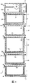
Fig. 1 is the front view of disclosed refrigerated storage or refrigeration equipment among undelegated International Patent Application PCT/GB00/03521 (WO01/20237) of the applicant, and expression respectively has vertical arrangement of the drawer of a bin;
Fig. 2 is the side view of equipment shown in Figure 1, and the following part of side panel is removed, so can see the side of drawer;
Fig. 3 is the sectional view of the III-III line in Fig. 2, and drawer is closed.
Fig. 4 is the sectional view of IV-IV line in Fig. 1;
Fig. 5 (a) and 5 (b) are respectively the plane and the sectional view of lid, represent the device of its sealing, cooling and draining in detail;
Fig. 6 is the schematic diagram of Fig. 5 (a) and a plurality of lids of 5 (b) expression, represents its drainage arrangement separately;
Fig. 7 (a) and 7 (b) are bottom plan view and the sectional views that is applicable to the lid of fan coil cooling system;
Fig. 8 (a), 8 (b) and 8 (c) are the details of the partial cross section of the front view of the front of desk-top refrigerating equipment and side and amplification, and it has the layout different with Fig. 1-4;
Fig. 9 (a), 9 (b) and 9 (c) are respectively front elevation view and two sectional views of a refrigerating equipment, and the prior art of the Ewen of this equipment and front is similar, but are devoted to many problems wherein;
Figure 10 (a), 10 (b) and 10 (c) are the partial cross section cutaway views of the refrigerating equipment among Fig. 9 (a), 9 (b) and 9 (c), are illustrated in the variety of way that prevents thermograde in each compartment of this equipment;
Figure 11 is the partial cross section cutaway view, is illustrated in the syndrome heating between bin and its lid, prevents to freeze at the faying face of bin/lid with this;
Figure 12 is the side schematic view of the bin of two cover lids, and each bin has the heater of the outer surface of warm its exposure;
Figure 13 is the schematic diagram corresponding to the side of Figure 12, but expression is to be used for the fan of blow air to the bin outer surface that exposes, and air selectively is heated; With
Figure 14 (a), 14 (b) and 14 (c) are the sectional views of fan coil device, Figure 14 (a) is the sectional view of the Y-Y line (b) from the bin back along Figure 14,14 (b) are the partial cross section figure of the Z-Z line from the side of fan coil along Figure 14 (a), and 14 (c) are the partial cross section figure of the X-X line from the top of fan coil unit along Figure 14 (a).
The specific embodiment
International Patent Application PCT/GB00/03521 of undelegated the applicant (WO01/20237) here as a reference, Fig. 1 of WO01/20237 is copied in the accompanying drawing of this specification to Fig. 4, and will introduce below and help understanding of the present invention.
Fig. 1 represents refrigerated storage or refrigeration equipment 2 according to WO01/20237 to Fig. 4.This equipment 2 has vertical cuboidal profile, and this equipment is that rectangular drawer 4 is formed by 5 front portions, these drawers 4 overlap up and down successively have top board 8, in the cabinet 6 of base plate 10, side plate 12 and back plate 14.All these plates can omit if this equipment can be built in the gap of other support members; Especially, if adjacent cabinet can be as relying on the effect of supporting or play side plate 12, then side plate 12 can be omitted. Plate 8,10,12,14 can be also can not be the structure of described equipment, still if not the structure of equipment, a framework (not expressing) just must be arranged in order to support the different piece of described equipment.If such framework is arranged, structurally just there is no need to have again these plates.
By the track or the chute of drawer side surface, drawer 4 can be that horizontal slip slips into and skid off cabinet 6, and this will be described in detail below.If back plate 14 not, as shown in Figure 2, in theory drawer 4 just can a more than direction by moving out in the cabinet 6.
Each drawer 4 has the container 16 of adiabatic open-topped charging basket shape, and at least one container 16 (in this case, as the drawer 4 of centre) is different with other container 16 degree of depth, promptly has different internal capacities.These containers 16 are called the storage assembly drawer or only are bins 16 in this this specification.Only stay narrow slit between the base plate of nethermost bin 16 and cabinet 6, the bin 16 at corresponding top has stayed enough spaces under the top of equipment 2, top board 8, the space that stays holds refrigeration machine 20 as compartment 18, for example comprises condenser and compressor.
The dark relatively bin 16 of middle drawer 4 is to be used to put the relative high article with other of bottle, and on the contrary, other shallow relatively bin 16 is put short relatively article.Limit main storage area with respect to traditional vertical refrigerating equipment by shelf and other assembly, all bins 16 have good aspect ratio, i.e. the ratio of the degree of depth that the width of import can reach with respect to compartment.Therefore after opening, drawer is easy to touch the each several part of bin 16 inside.
The inside of cabinet 6 is separated by five adiabatic lids 22,4 one lids of each drawer, normally the horizontal positioned plane time.When drawer 4 was closed, the top of opening of its bin 16 was by a suitable closed with covers, and the mode of its sealing will be described below.Lid 22 comprises cooling device 24, and this cooling device is the evaporimeter of known type, and the lower surface that cooling device 24 is placed on each lid 22 is used for cooling off the article of the bin 16 of this closed with covers.
When drawer 4 was closed, the front surface 28 on the basic plane that each bin 16 has was exposed to the outside.As everyone knows, front surface 28 can be a decoration panel.After drawer 4 was closed, the front surface 28 of bin 16 was adjacent with display floater 30 at its top and control, and this control and display floater 30 are used for this bin 16, panel 30 and front surface 28 coplanes.Panel 30 is supported by the leading edge 32 of corresponding lid 22.Panel 30 embeds the leading edge 32 of lid 22.
Described control and display floater 30 comprise a plurality of displays, switch and audible alarm unit, like this, provide a user interface to each bin.For example, this interface is normally used for selecting needing in the bin 16 temperature cooled off, and comprise that the change-over switch of demonstration, closure/disconnection and the snap frozen of temperature, light indication when drawer 4 is opened and the indication drawer time of opening surpass the audible alarm unit that temperature in the scheduled time or the bin 16 reaches the upper limit or lower limit.
The end of the front surface of each bin 16, is adjacent with slit 36, and as what describe below, this slit allows surrounding air to enter into cabinet 6 inside.For this reason, air gap 38 below the whole bottom surface 40 of each slit 36 and corresponding bin 16 is communicated with, and being communicated to the space 42 of each bin 16 back, space 42 is limited by the back plate 14 of cabinet 6, the inner surface of side plate 12 and the rear surface 44 of bin 16.As can be seen from Figure 4, extend in the back of each drawer 16 in space 42, is communicated to the compartment 18 of the refrigeration machine at cabinet 6 tops from the substrate 10 of cabinet 6.
The air gap 38 below the bin 16 and the space 42 of bin 16 back also are communicated with the air gap 38 of the side 48 of bin 6.Can selectively be provided with exhaust outlet 46 on the side plate 12 of cabinet 6 adjacent assemblies drawers 16, surrounding air also can enter by exhaust outlet.Show that as Fig. 3, Fig. 4 air gap 38 is around each bin, except the top of bin; So entering the surrounding air of cabinet 6 can freely circulate round side 48, bottom surface 40 and the back 44 of bin by slit 36.It may be noted that surrounding air can be freely in top surface 50 cocycles of lid 22.In order to allow air stream on uppermost lid 22, below the front surface 52 of refrigeration machine compartment 18, be provided with slit 36, above this lid 22, there has not been bin 16 again.
It may be noted that the piston effect of opening drawer 4 generations has sucked the inside of surrounding air to equipment 2, do not cause any problem in the present invention, in fact, this effect is favourable, and it has promoted the circulation of surrounding air in cabinet 6.
The refrigeration machine compartment 18 that Fig. 4 represents comprises impeller 54, gap 56 exhausts at the front surface place by being arranged on refrigeration machine compartment 18.As can be seen from Figure 1, these gap 56 horizontal-extendings pass the whole width of front surface 52.Impeller 54 is communicated with the space 42 of bin 16 back, is used to discharge the air in this space 42, advances the surrounding air that enters from the exhaust outlet 46 of slit 36 and any side so continuously.When entering into refrigeration machine compartment 18, air is conducted through the heat exchange matrix 58 of condenser.
Therefore, through the groove 36 of front, the surrounding air that also enters casing 6 through side ventilating opening 46 leaves casing 6 through the hole 56 that is located at ice-maker chamber's 18 front surfaces 52 if any, so surrounding air is by casing 6 circulations.More clearly, surrounding air access to plant 2, rapidly and the outer surface 40 of bin 16,44,48 contacts, before being introduced to space 42, earlier these surfaces are heated to environment temperature (perhaps substantially like this, because the result of skin resistance mean, because of the thermograde of crossing the bin wall thickness keeps an inferior environment boundary layer), upwards guide through space 42 by circulating air then.Arrow among Fig. 4 shows the circulation of air through device 2.Therefore, the inside of casing 6 is controlled near the environment temperature, has only the inside of each bin 16 to be cooled.
Be exposed to the air hotter by outer surface 28,40,44,48 than its inside with bin 16, on outer surface 28,40,44,48, there is not the condensed water problem, therefore do not have latent heat to pass to the problem of bin 16, the condensed water that perhaps enters casing 6 is difficult to cause and freezes and cross pollution.
In any case, cross pollution unlikely takes place because drawer 4 when closing each bin 16 be tightly sealed.So even bacterium enters in the casing 6, they also are not easy to enter in other bins 16.And two bins 16 also can not be opened simultaneously.Can comprise the device that pressure is done like this,, adopt and be similar to the sort of mechanism that adopts in the file cabinet, prevent from thus to open simultaneously more than one drawer 4 such as purpose for anti-obliquity.This mechanism will be described in the back.
When a bin 16 is opened, its top of opening wide can not run into a large amount of cold airs and overflow, when a bin 16 was closed, aspect the sealing cold air, the horizontal seal 60 that the present invention adopts was better than the vertical seal that is generally used for vertical type refrigeration and household freezer in essence.Though horizontal seal is very common at the horizontal refrigerator case, inconvenience and space problem that the present invention does not have the horizontal refrigerator case to exist, but similar with some aspects of more welcome vertical type device.Seal 60 is magnetic, such as by permanent magnet or operation electriomagnet or adopt hydraulic technique or pressure technology expands or the contact sealing.
Owing to must between the cold inner surface 62 of each bin 16 and outer surface 28,40,44,48, big thermograde be arranged, therefore bin 16 is made by the good heat-insulating material of effect, so under the situation that outer surface 28,40,44,48 keeps near environment temperature, gradient is easy to be maintained.Particularly do bin 16 and be optimal selection with phenolic foams or polyurethane foam (the epidermis formation composite construction that has alternatively, GRP (fiberglass) or Merlon).
If the content of certain bin 16 needs to isolate, bin 16 can be equipped with dismountable plug-in unit 64 so.Plug-in unit 64 has different shape and size, and can limit the compartment of many types.Such as, plug-in unit 64 can be the dividing plate that approaches, its length is corresponding to the length and the width of the bin 16 that holds dividing plate.Plug-in unit 64 can be a box with cover or not with cover, and perhaps plug-in unit 64 can comprise and is used for bottle is remained on the clip of correct position or the plate of dress egg etc.Plug-in unit 64 also can be gabion or frame.
As shown in Figure 2, one or more bins 16 can cooperate from installing to take out 2 and cover 66 with an adiabatic transmission.Can take away bin 16 2 from installing then, its heat insulating construction has guaranteed that content cools off in the limited time period.For example, bin 16 can be used as refrigerating box, can make content keep the state of cooling as far as possible for a long time with ice bag.Selectively, have to transmit and cover 66 bin 16 can be placed on device 2 neighbouring so that extra interim cold storage capacity to be provided, can have more bin 16 to put into this device 2 in this situation.The back will be described the layout that transmits lid in detail.
Cover 66 and also can comprise for transmitting by battery or combustion gas in-line power or by the refrigeration machine of main power source or automobile power source externally fed.
Though not shown in the schematic diagram of Fig. 1 to 4, but the international patent application no PCT/GB00/03521 of applicant's pending trial (WO01/20237) discloses a kind of mode, wherein bin 16 moves so that can enter bin 16 inside with the horizontal principal component of motion, enter between moving period at this, also break away from lid 22 with the less important component of vertical motion.
Fig. 5 (a) and 5 (b) illustrate the details of lid 22, when bin 16 is put into device 2, and lid and bin 16 sealings.The plane that Figure 18 (a) illustrates lid 22 is a rectangle.Parts profile below the lid 22 also shows with rectangular broken line.From the inside to surface, these parts are the evaporimeters 194 that are centrally placed in below the lid 22, are arranged in 196, one grooves 198 that are used for holding drain pan 196 and evaporimeter 194 below lid 22 of drain pan of the water of 194 times collection evaporimeters of evaporimeter, 194 drippages.
Preferably understand from Fig. 5 (a), this figure is the sectional view along the A-A line of Fig. 5 (a), and the limit under groove 198 dangles from lid 22 by is enclosed 200 and limited.A pair of rectangle compressible seal member 60 is positioned at the limit and encloses 200 lower surface 202, and one of them is in another the inside.Seal 60 is continuous, holds the opening that cross section is rectangular drainpipe 204 except one, and drainpipe is derived backward from drain pan 196.Drain pan 196 has an inclined bottom 206 with drainpipe 204 that water is led, and water is derived lid 22 from this position, will illustrate as Fig. 6.200 temperature of measuring in the cavity that is sealed by bin 16 and lid 22 are enclosed on the limit that the temperature sensor (not shown) is passed seal 60 tops.
How Fig. 6 becomes optimal placement if illustrating the independent drainpipe 208 of drawing from each drain pan 196 of multicompartment drawer device 2.This makes the risk of cross pollution reduce to minimum.Each pipe 208 comprises that one limits the U-shaped trap 210 of a sealing and is discharged to public water pond 212 respectively.As shown in the figure, dish 212 can be positioned on the compressor 214 of device 2, and therefore, along with the past of time, the heat that compressor 214 distributes makes in the dish 212 the water evaporation the same fast with the aggregation velocity of water in the dish 212 at least.In addition, perhaps alternatively, the condenser fan (not shown) of device 2 can be blown over the water surface in the dish 212 so that promote evaporation.
Fig. 7 (a) and 7 (b) illustrate the structure of another lid that is used for the fan coil cooling system, wherein extract out with air feeding assembly drawer 16 and from bin 16 by a remote fan coil unit.This system also is known as the forced ventilation system, the lid 22 among Fig. 7 (a) and 7 (b) be hollow and be separated and be used for controlling the air stream that this system relies on.Therefore, the cold air that the heat exchanger (not shown) cools down enters the air feed high pressure chest 216 that is positioned at lid 22 under the compressing of fan (not shown), air enters bin 16 from this chamber by air feed distributing trough 218, and distributing trough is around the base plate 220 of the bottom surface that limits lid 22.Hot-air is extracted out from bin 16 by the return-air hyperbaric chamber 222 in the middle of being distributed in, and this return-air hyperbaric chamber is communicated with bin 16 by the centre bore 224 in the base plate 220, and is communicated with fan by the pipe 226 in air feed hyperbaric chamber 216 around the extend past.Under the low pressure that fan produces, Hot air quilt suction return-air chamber 222 is delivered to heat exchanger then and is cooled, then by air supply chamber 216 recirculation.
In the foregoing description being arranged vertically of general drawer 4, as Fig. 8 (a), 8 (b), shown in 8 (c), drawer 4 layout that also can walk abreast as can be known.The front view of Fig. 8 (a) illustrates the rectangular stool formula of four drawers device 268, and drawer 4 wherein is two rows, two drawers 4 of every row.Therefore, an operating surface 270 arranged on drawer 4, be placed on two and arrange on the drawers to such an extent as to device 268 is enough low.Therefore this embodiment of the present invention is fit to be used as the chilled food preprocessing and/or the chamber equipment of preparing for a meal.
As shown in the figure, hang the position, can in limited available height, make the degree of depth maximization of drawer 4 by the side that refrigeration machine 272 and control panel 274 is placed on device 268 1 sides.And, the side view of Fig. 8 (b) and limit of raising 276 is arranged along the front end that the amplification sectional view of Fig. 8 (c) of Fig. 8 (a) X-X line shows operating surface 270, this limit helps to prevent that material unrestrained on the operating surface 270 from dropping to or falling in the following drawer 4.
Fig. 8 (a) and Fig. 8 (b) represent that also equipment 268 of the present invention can install Caster 278, and castor 278 is Height Adjustable, so that equipment 268 is arranged on the floor 280 that is not horizontal plane.
With reference to figure 9 (a), this is the front elevation view of refrigerating equipment 332, and this equipment is that the prior art of the Ewen that narrates previously is similar on function---major part of bin outer surface is exposed in the air below the environment temperature---but be devoted to a lot of problems of its existence.On outside surface, the horizontal equipment class of the equipment of Fig. 9 (a) and Fig. 8 (a) and Fig. 8 (b) expression like and also below working face 270 similar position have drawer 4, control panel 274 and refrigeration machine 272.Similarly, each drawer of Fig. 9 (b)---cross section along the A-A line among Fig. 9 (a)---expression is made up of lid in the cabinet 22 and bin 16, and bin 16 can move forward from cabinet in telescopic chute 74.Cross section among Fig. 9 (c)-Fig. 9 (a)-the shown chute 74 of bin 16 sides along the B-B line.
But, similar with the patent of Ewen, and different with aforesaid embodiment, do not have the component motion of bin 16 with respect to lid 22 vertical directions: replacement be, bin 16 just horizontal slip through the compact lid of installing 22.Have the slit between bin 16 and the lid 22, therefore require around the compartment that holds each drawer, to produce external steam barrier completely, overcome the problem of the transmission and the cross pollution of relevant moisture with this.Like this, as Fig. 9 (b) expression, the front panel 118 of each drawer extends beyond the slit of corresponding drawer, this slit be between the lid 22 or lid 22 and base plate 334 between the slit.The rear surface of the lap of each front panel 118 has the magnetic seal bar 336 of vertical direction, when drawer is closed, lap is by elastic packing, perhaps by all being suitable to the sealing of the magnetic attraction of the front surface of lid 22 and/or to the sealing of the magnetic attraction of base plate front surface.Also seal between the compartment of drawer is mutual; These are applicable to the situation of the working relation of permeating and moving between the adjacent drawer compartment.Also be applicable to from the drawer compartments draining: independent drainage pipeline (not expression) is drawn from each compartment respectively, and each pipeline has connected water pond, is similar to the draining configuration that top Fig. 6 represents.
The bin support member 338 that Fig. 9 (c) has also represented to have " L " tee section is dangled by chute 74 and descends, and the supporting component drawer 16 in a movable manner.The compartment of each drawer should have minimized volume, and this volume can hold bin 16 and corresponding chute 74.
Ideally, the compartment of each drawer should be thin and be to be made by not adiabatic material that all outer surfaces all are exposed in the surrounding air.This perfect condition is actually and can not reaches, even used the very thin material to help the conduction from the external world to the drawer compartments and promoted the convection current in the drawer compartments.In fact, along with the past of time, owing to the insulation effect in shell and bin 16 ambient air chambeies, add the refrigeration in the slit between bin 16 and the lid 22, in the inside formation temperature gradient of the compartment that seals.In addition, at the compartment outer surface adjacent with other compartment adiabatic well (Insulating trap) will appear.This is with further cooling package drawer 16 ambient airs, so strengthened thermograde.
For this reason, Figure 10 (a), Figure 10 (b) have proposed three kinds of different minimized methods of the effect that makes thermograde with Figure 10 (c), have also proposed the cooling in each drawer compartments of equipment of Fig. 9 (a), Fig. 9 (b) and Fig. 9 (c) expression.Figure 10 (a) has circulating fan 340 on the passage 342 of drawer compartments 344 back, this fan sends back to it compartment 344 again from compartment 344 extracting airs.The air circulation that produces in the compartment 344 makes the outer surface of bin 16 keep mean temperature like this.Figure 10 (b) expression be electricity or hot gas heater 346 below the bin 16, this heater is used for producing convective air flow in compartment 344, and the most outer surface of heating component drawer 16 is near the temperature of environment, to environment temperature or be higher than environment temperature.The slit 348 that Figure 10 (c) representation class is described in the accompanying drawing 4 like top accompanying drawing 1 is illustrated in around the slit of drawer compartments 334 or the air gap between the drawer compartments 334, rather than around the air gap of bin 16.Though can't see at Figure 10 (c), air gap 348 can extend to the back of side, downside and the compartment 334 of drawer compartments 334.And, can heat the air in the air gap 348 if desired.
Figure 11 represents that syndrome heating (trace heat) is icing in order to prevent at the faying face 376 of bin/lid from the skirt section that lid 22 dangles.Can finish heating by electrical heating elements 278 or hot gas device, can be heat constantly also can be when needs are opened bin 16 heating.
In various variations of the present invention, the syndrome heater that Figure 11 represents is applicable to aforesaid configuration, the relative motion of lid 22 and bin 16 in this configuration (motion of preferred vertical direction) has been removed the sealing of lid and bin and bin has been broken away from (perhaps antithesis) 22 times from lid, enters wherein so could open bin fully.
Also can from the various heat release parts of refrigeration machine, obtain heat,, come the faying face or 16 outer surfaces of the bin in the drawer compartments of heating component drawer/lid as heat release of heat exchanger, motor etc.Saved the energy like this with regard to having utilized used heat, otherwise these used heat will be discharged in the atmosphere.
The thought of the outer surface of the bin 16 in the heating drawer compartments is expanded in Figure 12, and Figure 12 has represented that the heating element heater 380 that wriggles is positioned at or faces the outer surface of bin 16.Corresponding heating element heater (not have to represent) can be positioned at or face the outer surface of bin 16, also can be positioned at or face the bottom or the external rear face of bin 16, can be below bin 16 or in the back of bin 16.Element 380 can be by the refrigerant tubing that is about 40 degrees centigrade, perhaps by the hot gas pipeline heat supply that is about 80 degrees centigrade.In this respect with reference to Figure 14 (a), Figure 14 (b) and Figure 14 (c).Can select, element 380 can be low power resistive element, also can be the syndrome heating cushion.
Figure 13 represent tangential fan 382 or receded disk impeller be how to be used to hot-air blow to bin 16 outer surface around.Described hot-air can be extracted out from following position, and for example, the part of the heat exchanger matrix of condenser or the heating in the equipment from equipment is as the motor place of fan or compressor.The air of fans drive stream is also beneficial: no matter whether heat, all help to prevent the bottom of bin 16 and below the lid 22 of another bin 16 between air gap in condensation appears.
For the hull-skin temperature of the heating component drawer target to the temperature that is higher than environment, though compressed-air actuated effect is expected to improve a little temperature, effect is very little basically, even can ignore.
Figure 14 (a), Figure 14 (b) and Figure 14 (c) are sectional views, and expression tangential fan 382 or receded disk impeller are mounted in the part of the fan coil unit 384 of bin 16 back.The composition of described fan coil unit 384 14 (a) is in conjunction with the accompanying drawings just understood easily, comprising: adiabatic is cubical housing 386 basically, and this housing is positioned at the back of the drawer compartments of whole bin 16 back.Housing 386 has forward the pipeline that extends, and this pipeline is communicated with bin 16 by lid 22, and promptly steam line 388 sides at center are two and return air duct 390.
Central gas-supply pipeline 388 is aimed at tangential fan 382, and this fan provides power near the top of housing 386 by motor 392, and it is normally columniform and around horizontal rotational shaft.In fan 382 work, the driving cold air passes central gas-supply pipe 388 and enters into bin 16 via the pipeline in the lid 22 (not expression).
Figure 14 (a) also represents the connection of cooling coil 394, fluid pipeline 398 the supply system cryogens are to the upper end of coil pipe 394, HAI Heated Air Intake pipe 400 also is arranged on the upper end of coil pipe 394, and exhaust tube 402 is connected to the bottom of this cooling coil 394, is used for from coil pipe 394 suction refrigeration agent.
Figure 14 (a) has shown also the pedestal of housing 386 is how to support drain pan 404 to collect the moisture droplets ooze from this cooling coil 394.Moisture is discharged by drainpipe 406 from drain pan 404.Advantageously, as shown, hot air intake pipe 400 is used for making drain pan not freeze along drain pan 404 extensions, and, promote water to flow freely and discharge by drainpipe 406 along drain pan 404.
Though the solution that top Figure 10 describes to Figure 14 has been initially the problem that the refrigerator that is similar to the prior art that Ewen gives an example exists of solving, some or all these solution all is applicable to the refrigerator of undelegated International Patent Application PCT/GB/00/03521 (WO01/20237) design of the applicant.
The present invention have use widely and help creating that appropriate condition is stored, handles, sent with charge free, transportation and supply items, especially:
Be not only cooling even the precise dose when being included in heating and humidity control;
By the mechanical protection of stored goods;
Aseptic storage does not have the risk of cross pollution;
Can be chosen under the partial vacuum condition and store;
Selectively under the environment of corrosion-resistant inhibition gas, store;
The isolation of stored goods, the defence stored goods is vibrated and is stirred;
Sealing preservation, radiation proof and biohazard.
In a word, should show scope of the present invention from appended claim and other the general remark rather than the special description of front.Explanation of the invention should be appreciated that combined together being described of characteristics of each embodiment, though this combination has its advantage, and much can implement independently in these characteristics.So, no matter still having exceeded these invention thought in the scope of the invention thought of statement here, these above-mentioned characteristics are considered to respectively to have its patentability.
Claims (18)
1, a kind of refrigerating equipment, comprising:
At least one thermally insulated container, this thermally insulated container defines the outer surface that comprises first and second sides;
A structure, this structure qualification container compartment, can from this compartment, extract out and open described container and can the access internal tank, thereby and this container can return compartment and close this container, this container is used to refrigerate any article; With
Heater in order to when this container is in the container compartment, heats first and second side external surfaces of container at least.
2, equipment as claimed in claim 1, wherein when this container was in the container compartment, this heater also was used for the bottom outer surface and the external rear face of heating container.
3, equipment as claimed in claim 1 or 2, wherein this heater is set in order to the outer surface that heats described container to being higher than environment temperature.
4, equipment as claimed in claim 1 or 2, wherein this heater has utilized the recovery heat of the heat generating components of this equipment.
5, equipment as claimed in claim 4, wherein this heat generating components comprises refrigeration machine, heat exchanger or motor.
6, equipment as claimed in claim 1 or 2, wherein this container compartment has heating element heater or the heating cushion in the face of described container outer surface.
7, equipment as claimed in claim 1 or 2, wherein this container outer surface has heating element heater or heating cushion.
8, a kind of refrigerating equipment, comprising:
Open-topped thermally insulated container, this container defines the outer surface that comprises first and second sides;
Adiabatic lid, the open top that is used to seal described container;
Cooling device, the inside that is used to cool off described container;
Support the structure of described container, lid and cooling device; With
Heater is used for making the outer surface of described container to be exposed to the air that is higher than environment temperature;
Container wherein is installed on this structure, and container can be with respect to the motion of this structure and described lid, opening this container or to close this container, and inside that can this container of access when container is opened; Wherein, container is during by described closed with covers, and first and second side external surfaces of container are exposed in the air that is higher than environment temperature at least.
9, equipment as claimed in claim 8 wherein also comprises other syndrome heater, is used for heating partly the faying face between described container and the lid.
10, equipment as claimed in claim 9, wherein said syndrome heater can adopt heating and/or fluid line.
11, equipment as claimed in claim 10 includes refrigerant liquid or hot gas in the wherein said fluid line.
12, as each described equipment of claim 9 to 11, wherein the syndrome heating continues.
13, as each described equipment of claim 8 to 11, wherein the syndrome heating is only just used when needs are opened this container.
14, equipment as claimed in claim 8 wherein also comprises:
EGR makes circulating air circulation around this container, and described container outer surface is exposed in this circulating air.
15, equipment as claimed in claim 14, wherein this EGR comprises fan.
16, equipment as claimed in claim 15, wherein this EGR comprises heater (346,380), this heater around container produces convection current.
17, equipment as claimed in claim 16, when this container is in when cutting out, described heater (346) be positioned at container below.
18, as each described equipment of claim 14 to 17, wherein said EGR is drawn hot-air from the heat generating components of this equipment.
Applications Claiming Priority (6)
| Application Number | Priority Date | Filing Date | Title |
|---|---|---|---|
| GB0106164.7 | 2001-03-13 | ||
| GB0106164A GB2367353B (en) | 2000-09-13 | 2001-03-13 | Improvements in or relating to cold storage |
| GB0118281A GB2368898B (en) | 2000-09-13 | 2001-07-26 | Improvements in or relating to cold storage |
| GB0118281.5 | 2001-07-26 | ||
| GB0129853.8 | 2001-12-13 | ||
| GBGB0129853.8A GB0129853D0 (en) | 2001-12-13 | 2001-12-13 | Drawer transport systems |
Publications (2)
| Publication Number | Publication Date |
|---|---|
| CN1496470A CN1496470A (en) | 2004-05-12 |
| CN1321305C true CN1321305C (en) | 2007-06-13 |
Family
ID=27256098
Family Applications (3)
| Application Number | Title | Priority Date | Filing Date |
|---|---|---|---|
| CNB028064348A Expired - Fee Related CN1249394C (en) | 2001-03-13 | 2002-03-13 | Airflow management in cold storage appliances |
| CNB028064321A Expired - Fee Related CN100370204C (en) | 2001-03-13 | 2002-03-13 | Drawer storage device |
| CNB02806433XA Expired - Fee Related CN1321305C (en) | 2001-03-13 | 2002-03-13 | Use of heat in cold storage appliances |
Family Applications Before (2)
| Application Number | Title | Priority Date | Filing Date |
|---|---|---|---|
| CNB028064348A Expired - Fee Related CN1249394C (en) | 2001-03-13 | 2002-03-13 | Airflow management in cold storage appliances |
| CNB028064321A Expired - Fee Related CN100370204C (en) | 2001-03-13 | 2002-03-13 | Drawer storage device |
Country Status (14)
| Country | Link |
|---|---|
| US (5) | US7159415B2 (en) |
| EP (4) | EP1726896A1 (en) |
| JP (3) | JP4146237B2 (en) |
| CN (3) | CN1249394C (en) |
| AT (2) | ATE423950T1 (en) |
| AU (3) | AU2002238775B2 (en) |
| BR (3) | BR0208089A (en) |
| CA (3) | CA2439706A1 (en) |
| DE (2) | DE60231292D1 (en) |
| ES (1) | ES2322130T3 (en) |
| HK (2) | HK1058541A1 (en) |
| IL (3) | IL157833A0 (en) |
| NZ (3) | NZ528759A (en) |
| WO (3) | WO2002073105A1 (en) |
Families Citing this family (118)
| Publication number | Priority date | Publication date | Assignee | Title |
|---|---|---|---|---|
| GB0129853D0 (en) | 2001-12-13 | 2002-01-30 | Applied Design & Eng Ltd | Drawer transport systems |
| JP4166005B2 (en) * | 2001-08-10 | 2008-10-15 | 株式会社荏原製作所 | Trap apparatus and method |
| AU2003901561A0 (en) | 2003-04-07 | 2003-05-01 | Dna Holdings Pty Ltd | Refrigerated cabinet |
| US20100205992A1 (en) * | 2003-04-07 | 2010-08-19 | Dna Holdings Pty Ltd | Refrigerated cabinet |
| GB2398355B (en) * | 2003-09-05 | 2004-12-29 | Applied Design & Eng Ltd | Improvements in or relating to seals |
| US7430937B2 (en) | 2004-01-16 | 2008-10-07 | Maytag Corporation | Rack and pinion stabilizer system |
| ATE468779T1 (en) * | 2004-04-13 | 2010-06-15 | Whirlpool Co | DRAWER CHARGER |
| KR100652583B1 (en) * | 2004-07-29 | 2006-12-06 | 엘지전자 주식회사 | Refrigerator having basket lift apparatus |
| GB2415490A (en) * | 2004-09-06 | 2005-12-28 | Applied Design & Eng Ltd | Cold-storage appliance |
| CA2605550A1 (en) | 2005-04-22 | 2006-11-02 | Eric Hoersten | System and method for selling a rental media product |
| US7575242B2 (en) * | 2005-06-16 | 2009-08-18 | Siemens Medical Solutions Usa, Inc. | Collimator change cart |
| US7228698B2 (en) * | 2005-06-30 | 2007-06-12 | Premark Feg L.L.C. | Refrigeration unit |
| WO2007010267A2 (en) * | 2005-07-20 | 2007-01-25 | Applied Design & Engineering Ltd | Improvements in or relating to cold storage |
| US7530558B2 (en) * | 2005-10-28 | 2009-05-12 | Edison Nation, Llc | Cutting board assembly having drawer with variable volume containment space |
| US20070108686A1 (en) * | 2005-10-28 | 2007-05-17 | Ccb Technologies, Llc | Cutting board assembly |
| US7827811B2 (en) * | 2006-01-09 | 2010-11-09 | Maytag Corporation | Refrigerator control including a hidden features menu |
| BRPI0706478A2 (en) * | 2006-01-13 | 2011-03-29 | Delfield Company Llc | storage system having variable temperature, and method for heating and / or cooling a storage system |
| US8672732B2 (en) | 2006-01-19 | 2014-03-18 | Schneider Electric It Corporation | Cooling system and method |
| US7365973B2 (en) | 2006-01-19 | 2008-04-29 | American Power Conversion Corporation | Cooling system and method |
| US7401474B2 (en) * | 2006-02-27 | 2008-07-22 | Adda Corp. | Thermal food storage cabinet |
| KR100780826B1 (en) | 2006-03-21 | 2007-11-29 | 설승원 | storehouse for medical exclusive |
| JP4641967B2 (en) * | 2006-03-31 | 2011-03-02 | 三洋電機株式会社 | Storage |
| US20080016886A1 (en) * | 2006-07-20 | 2008-01-24 | Helmer, Inc. | Freezer with positive pressure storage cabinet |
| US8322155B2 (en) | 2006-08-15 | 2012-12-04 | American Power Conversion Corporation | Method and apparatus for cooling |
| US8327656B2 (en) * | 2006-08-15 | 2012-12-11 | American Power Conversion Corporation | Method and apparatus for cooling |
| US9568206B2 (en) | 2006-08-15 | 2017-02-14 | Schneider Electric It Corporation | Method and apparatus for cooling |
| US7681404B2 (en) | 2006-12-18 | 2010-03-23 | American Power Conversion Corporation | Modular ice storage for uninterruptible chilled water |
| WO2008077425A1 (en) * | 2006-12-22 | 2008-07-03 | Carrier Corporation | A furniture for displaying goods on sale |
| US8425287B2 (en) | 2007-01-23 | 2013-04-23 | Schneider Electric It Corporation | In-row air containment and cooling system and method |
| US20080179805A1 (en) * | 2007-01-28 | 2008-07-31 | Ccb Technologies, Llc | Frame having peeler and grater in cutting board support platform |
| DE102007005953A1 (en) * | 2007-02-06 | 2008-08-07 | BSH Bosch und Siemens Hausgeräte GmbH | Refrigeration unit with circulating air cooling |
| DE102007005948A1 (en) * | 2007-02-06 | 2008-08-07 | BSH Bosch und Siemens Hausgeräte GmbH | Refrigeration unit with telescopic extension |
| CN101755495B (en) | 2007-05-15 | 2013-10-16 | 美国能量变换公司 | Methods and systems for managing facility power and cooling |
| DE202007013358U1 (en) * | 2007-05-30 | 2008-11-20 | Liebherr-Hausgeräte Ochsenhausen GmbH | Fridge and / or freezer |
| JP4934537B2 (en) * | 2007-08-02 | 2012-05-16 | 日立アプライアンス株式会社 | refrigerator |
| KR100901022B1 (en) * | 2007-09-13 | 2009-06-04 | 엘지전자 주식회사 | Refrigerator |
| US9886809B2 (en) | 2007-09-28 | 2018-02-06 | Redbox Automated Retail, Llc | Article dispensing machine and method for auditing inventory while article dispensing machine remains operational |
| US8768789B2 (en) | 2012-03-07 | 2014-07-01 | Redbox Automated Retail, Llc | System and method for optimizing utilization of inventory space for dispensable articles |
| US8712872B2 (en) | 2012-03-07 | 2014-04-29 | Redbox Automated Retail, Llc | System and method for optimizing utilization of inventory space for dispensable articles |
| DE102007048575A1 (en) * | 2007-10-10 | 2009-04-16 | BSH Bosch und Siemens Hausgeräte GmbH | The refrigerator |
| KR100894479B1 (en) * | 2007-11-30 | 2009-04-22 | 엘지전자 주식회사 | Refrigerator with switching room |
| US20090167130A1 (en) * | 2007-12-28 | 2009-07-02 | Bagawathkumar Chellappan | A dual drawer bottom mount freezer and mullion |
| US7681871B2 (en) * | 2008-03-02 | 2010-03-23 | Edison Nation, Llc | Cutting board assembly having cutting board storage recess |
| JP5031640B2 (en) * | 2008-03-31 | 2012-09-19 | シャープ株式会社 | refrigerator |
| US8219362B2 (en) | 2009-05-08 | 2012-07-10 | American Power Conversion Corporation | System and method for arranging equipment in a data center |
| US8100486B2 (en) * | 2009-07-10 | 2012-01-24 | Prince Castle, LLC | Food storage unit with drawer having impact-absorbing seal |
| US9104990B2 (en) | 2009-09-05 | 2015-08-11 | Redbox Automated Retail, Llc | Article vending machine and method for exchanging an inoperable article for an operable article |
| US8996162B2 (en) | 2009-09-05 | 2015-03-31 | Redbox Automated Retail, Llc | Article vending machine and method for exchanging an inoperable article for an operable article |
| US8701737B2 (en) | 2009-11-09 | 2014-04-22 | LDM Products, Inc | Retractable computer rack aisle roof |
| KR101104567B1 (en) * | 2009-12-18 | 2012-01-11 | 엘지전자 주식회사 | Drawer apparatus for refrigerator |
| US8360539B2 (en) * | 2010-02-26 | 2013-01-29 | Electrolux Home Products, Inc. | Drawer assembly |
| US8671712B2 (en) * | 2010-03-25 | 2014-03-18 | Whirlpool Corporation | Upper freezer basket guided by lower freezer basket divider |
| KR101221237B1 (en) | 2010-06-09 | 2013-01-11 | 위니아만도 주식회사 | A drawer-type Refrigerator in use with cold shield |
| MX2012014266A (en) * | 2010-06-18 | 2013-06-28 | Metro Ind Inc | Security system for a medical emergency crash card. |
| US8538581B2 (en) | 2010-09-03 | 2013-09-17 | Redbox Automated Retail, Llc | Article vending machine and method for authenticating received articles |
| US9569911B2 (en) | 2010-08-23 | 2017-02-14 | Redbox Automated Retail, Llc | Secondary media return system and method |
| US8688413B2 (en) | 2010-12-30 | 2014-04-01 | Christopher M. Healey | System and method for sequential placement of cooling resources within data center layouts |
| US8978747B2 (en) | 2010-12-31 | 2015-03-17 | Microsoft Corporation | Deicing louvers for datacenter applications |
| DE102011006605A1 (en) * | 2011-03-31 | 2012-10-04 | BSH Bosch und Siemens Hausgeräte GmbH | Refrigerating appliance with superimposed refrigerated drawers |
| WO2012174171A2 (en) | 2011-06-14 | 2012-12-20 | Redbox Automated Retail, Llc | System and method for substituting a media article with alternative media |
| US9495465B2 (en) | 2011-07-20 | 2016-11-15 | Redbox Automated Retail, Llc | System and method for providing the identification of geographically closest article dispensing machines |
| US9348822B2 (en) | 2011-08-02 | 2016-05-24 | Redbox Automated Retail, Llc | System and method for generating notifications related to new media |
| CA2844328A1 (en) | 2011-08-12 | 2013-02-21 | Redbox Automated Retail, Llc | System and method for applying parental control limits from content providers to media content |
| US20130045540A1 (en) * | 2011-08-19 | 2013-02-21 | Hach Company | Method and apparatus for capturing and retesting an online toc excursion sample |
| US9830410B2 (en) | 2011-12-22 | 2017-11-28 | Schneider Electric It Corporation | System and method for prediction of temperature values in an electronics system |
| CN104137105B (en) | 2011-12-22 | 2017-07-11 | 施耐德电气It公司 | Impact analysis on temporal event to the temperature in data center |
| WO2013106768A1 (en) * | 2012-01-12 | 2013-07-18 | EMS Mind Reader LLC | Apparatus for and method of making a storage drawer |
| KR20130116741A (en) * | 2012-04-16 | 2013-10-24 | 엘지전자 주식회사 | A sealing structure for a vegetables container of a refrigerator |
| US9747253B2 (en) | 2012-06-05 | 2017-08-29 | Redbox Automated Retail, Llc | System and method for simultaneous article retrieval and transaction validation |
| KR101918059B1 (en) * | 2012-07-23 | 2018-11-13 | 엘지전자 주식회사 | Refrigerator with sealing apparatus for drawer |
| DE102012213542A1 (en) * | 2012-08-01 | 2014-02-06 | Goselig UG | Cold storage device and cooling system arrangement |
| US20140139088A1 (en) * | 2012-11-21 | 2014-05-22 | Whirlpool Corporation | Transparent touch displays for refrigerator drawers |
| DE102012221499A1 (en) * | 2012-11-23 | 2014-05-28 | BSH Bosch und Siemens Hausgeräte GmbH | Domestic refrigerating appliance with a display means for a container lid |
| CN103968632B (en) * | 2013-01-31 | 2016-08-10 | 松下电器产业株式会社 | Drying device and possess the refrigerator of this drying device |
| US9345382B2 (en) | 2013-06-19 | 2016-05-24 | Bsh Home Appliances Corporation | Dishwasher with sliding dish rack |
| PL3052871T3 (en) * | 2013-10-03 | 2018-08-31 | Arçelik Anonim Sirketi | A refrigerator comprising a drawer with humidity control |
| CN105723177B (en) * | 2013-10-15 | 2018-08-31 | 株式会社Natomics | Heat-transfer surface guard method and humid air cooling means |
| DE102014104919A1 (en) * | 2014-04-07 | 2015-10-08 | Paul Hettich Gmbh & Co. Kg | Furniture or household appliance and fitting unit for a piece of furniture or household appliance |
| ES2755356T3 (en) * | 2014-11-14 | 2020-04-22 | Inter Ikea Sys Bv | Improved cabinet comprising a roller wheel assembly |
| US9857120B2 (en) * | 2015-01-08 | 2018-01-02 | Reflect Scientific Inc. | System and methods for improvements to a ultra-low temperature bio-sample storage system |
| KR101741751B1 (en) * | 2015-06-17 | 2017-05-31 | 동부대우전자 주식회사 | Refrigerator having cool airflowload damper apparatus and controlling method for the same |
| CN105674675B (en) * | 2015-12-29 | 2018-07-13 | 青岛海尔股份有限公司 | Closed enclosure |
| CN105650966A (en) * | 2016-03-28 | 2016-06-08 | 朱德金 | Seafood refrigeration cabinet |
| MY189522A (en) * | 2016-08-10 | 2022-02-16 | Sharp Kk | Refrigerator |
| CN106766505B (en) * | 2016-11-29 | 2019-05-03 | 青岛海尔股份有限公司 | Refrigerator |
| CN107062735B (en) * | 2016-12-30 | 2019-12-06 | 青岛海尔股份有限公司 | Refrigerator and control method thereof |
| CN106800143B (en) * | 2017-01-22 | 2017-11-24 | 湖北京山康宏装饰材料有限公司 | One kind insulation case apparatus |
| DE202017104092U1 (en) * | 2017-07-10 | 2018-10-11 | Kesseböhmer Holding Kg | Temperature control unit for a cabinet |
| CN107633617A (en) * | 2017-09-05 | 2018-01-26 | 无锡江普创新科技有限公司 | A kind of vehicle moving express delivery cabinet and its express station for vegetable dispatching |
| CN107830674A (en) * | 2017-11-02 | 2018-03-23 | 广东英得尔实业发展有限公司 | A kind of semiconductor car refrigerator |
| CN107928182B (en) * | 2017-11-10 | 2019-07-16 | 重庆工程职业技术学院 | Student education archive management system |
| CN107997843A (en) * | 2017-11-24 | 2018-05-08 | 郝晓凤 | A kind of oral care systems |
| CH714572A1 (en) * | 2018-01-18 | 2019-07-31 | Novaris Gmbh | Cover for a drawer body and vacuum drawer device with a lid. |
| US20210247075A1 (en) * | 2018-02-05 | 2021-08-12 | Alto-Shaam, Inc. | Steam Generation and Drain System for Modular Oven |
| US10986843B2 (en) * | 2018-02-05 | 2021-04-27 | Alto-Shaam, Inc. | Combination drain system for multizone oven |
| CN109696005A (en) * | 2018-02-24 | 2019-04-30 | 青岛海尔股份有限公司 | Refrigerator and its conduit assembly |
| KR20190109069A (en) * | 2018-03-16 | 2019-09-25 | 엘지전자 주식회사 | Refrigerator |
| US20190344930A1 (en) * | 2018-05-14 | 2019-11-14 | Haier Us Appliance Solutions, Inc. | Temperature controlled container storage system |
| CN110599698A (en) | 2018-06-13 | 2019-12-20 | 菜鸟智能物流控股有限公司 | Goods storing and taking cabinet and method for receiving and distributing goods by using same |
| CN108669857A (en) * | 2018-06-28 | 2018-10-19 | 北京铂阳顶荣光伏科技有限公司 | A kind of drawer |
| CA3104892A1 (en) * | 2018-06-29 | 2020-01-02 | Kason Industries, Inc. | Cold room combination vent and light |
| US10378814B1 (en) | 2018-07-10 | 2019-08-13 | Ruth Gaye | Refrigerator or freezer organization apparatus |
| CN109094952B (en) * | 2018-07-14 | 2019-12-13 | 安徽细胞之星生物科技有限公司 | Special vehicle-mounted storage and transportation equipment for stem cells and bioactive preparations |
| CN111059857B (en) * | 2018-12-11 | 2020-10-09 | 海尔智家股份有限公司 | Refrigerator with a door |
| CN109780792B (en) * | 2018-12-28 | 2022-10-18 | 海尔智家股份有限公司 | Refrigerator with a door |
| CN109550538A (en) * | 2018-12-29 | 2019-04-02 | 贵州大学 | A kind of Mechanics of Materials Teaching experimental desk |
| CN111912153A (en) * | 2019-05-10 | 2020-11-10 | 青岛海尔电冰箱有限公司 | Refrigerating and freezing device |
| CN110301769B (en) * | 2019-07-12 | 2021-01-15 | 赣州宇辉金属有限公司 | Sheet metal part |
| CN110403369B (en) * | 2019-07-31 | 2022-04-08 | 邵美琪 | Intelligent storage cabinet for patent certificates |
| CN110759013A (en) * | 2019-10-31 | 2020-02-07 | 中广核研究院有限公司 | Horizontal transfer pore channel between hot chambers |
| CH716911A2 (en) * | 2019-12-09 | 2021-06-15 | Prins Intellectual Property Ag | Multi-layer lid for a vacuum drawer device. |
| JP7471147B2 (en) | 2020-05-29 | 2024-04-19 | 東芝ライフスタイル株式会社 | refrigerator |
| CA3189019A1 (en) | 2020-08-12 | 2022-02-17 | Adam A. AFZALI | Modular dispenser for single objects |
| CN111955965A (en) * | 2020-08-26 | 2020-11-20 | 辛海勇 | Connecting piece for cabinet |
| US11779191B2 (en) * | 2021-02-19 | 2023-10-10 | Midea Group Co., Ltd. | Wheel shelf for a dish washing appliance |
| DE102021205354A1 (en) | 2021-05-26 | 2022-12-01 | BSH Hausgeräte GmbH | Portable cool box, drawer and furniture front |
| US20240085087A1 (en) * | 2022-09-08 | 2024-03-14 | Pepsico, Inc. | Modular refrigeration system for storing products |
| CN116603577B (en) * | 2023-05-08 | 2023-10-20 | 广东汇绿实验室设备科技有限公司 | Dangerous goods storage equipment for chemical industry experiments |
Citations (5)
| Publication number | Priority date | Publication date | Assignee | Title |
|---|---|---|---|---|
| US1337696A (en) * | 1916-03-25 | 1920-04-20 | Montague Iron Works Corp | Refrigerating-cabinet |
| US2460469A (en) * | 1946-12-07 | 1949-02-01 | Frex O Mat Corp | Refrigerator having a door heating device |
| DE808845C (en) * | 1949-11-29 | 1951-07-19 | Gunner Jensen | Fridge |
| DE1129972B (en) * | 1960-07-05 | 1962-05-24 | Bbc Brown Boveri & Cie | Deep-freeze furniture with electrical resistance heating to avoid liquid condensation on the outside surface |
| DE4237293A1 (en) * | 1992-11-05 | 1994-05-11 | Licentia Gmbh | Refrigerator or freezer with door seal condensation inhibitor system - has internal warm coolant pipe circuit pressed into good thermal contact with housing in door region to promote efficient heat transfer |
Family Cites Families (105)
| Publication number | Priority date | Publication date | Assignee | Title |
|---|---|---|---|---|
| GB341745A (en) | 1930-02-12 | 1931-01-22 | Autoset Clamp Company Ltd | Extensible side supports for drawers and like slidable structures |
| US2077739A (en) * | 1932-10-29 | 1937-04-20 | Roy B Bryant | Refrigerator |
| GB418489A (en) | 1934-03-28 | 1934-10-25 | Morris Heating Appliances Ltd | Improvements relating to refrigerators |
| US2223234A (en) * | 1939-05-27 | 1940-11-26 | Charles A Stemme | Temperature controlled container |
| GB579071A (en) | 1940-02-10 | 1946-07-23 | Guyon Locke Crocheron Earle | Refrigerator |
| GB581121A (en) | 1940-11-09 | 1946-10-02 | Guyon Locke Crocheron Earle | Refrigerator |
| US2360533A (en) | 1942-04-15 | 1944-10-17 | Standard Railway Equipment Mfg | Locking and ventilating means for hatch covers |
| US2338889A (en) * | 1942-09-11 | 1944-01-11 | Westinghouse Electric & Mfg Co | Refrigeration apparatus |
| US2386757A (en) * | 1942-09-30 | 1945-10-16 | Gen Fireproofing Co | Drawer suspension |
| FR962531A (en) | 1943-06-21 | 1950-06-14 | ||
| GB602329A (en) | 1944-01-15 | 1948-05-25 | Guyon Locke Crocheron Earle | Improvements in or relating to refrigerators |
| GB602590A (en) | 1944-01-15 | 1948-05-31 | Guyon Locke Crocheron Earle | Improvements in or relating to refrigerators |
| FR933333A (en) | 1946-09-09 | 1948-04-16 | Cooler formed by assemblable sections with drawers | |
| GB620460A (en) | 1947-01-20 | 1949-03-24 | Harris & Sheldon Ltd | Improvements in anti-friction suspension rails for drawers and the like |
| GB628939A (en) | 1947-10-01 | 1949-09-07 | Rubery Owen & Co Ltd | Filing and like cabinets |
| CH269462A (en) | 1950-02-07 | 1950-07-15 | Merz Meyer Alice | Double pull-out device for drawers. |
| US2780510A (en) | 1953-11-12 | 1957-02-05 | Craig Machine Inc | Drawer suspension apparatus for filing cabinets and the like |
| US2894845A (en) * | 1955-04-18 | 1959-07-14 | Gen Electric | Methods of preserving fresh foods |
| US2948498A (en) * | 1956-10-04 | 1960-08-09 | Trane Co | Roll-out mechanism |
| US2942926A (en) * | 1957-12-06 | 1960-06-28 | Jr Joseph Pavelka | Food server |
| US3058320A (en) * | 1960-06-07 | 1962-10-16 | Foster Refrigerator Corp | Refrigerator |
| GB948223A (en) | 1961-04-24 | 1964-01-29 | Gen Motors Corp | Refrigerator |
| US3206943A (en) * | 1962-02-09 | 1965-09-21 | Borg Warner | Refrigerator having a movable refrigeration unit therein |
| US3230733A (en) | 1962-04-10 | 1966-01-25 | Emhart Corp | Refrigeration system and elements thereof |
| FR1377844A (en) | 1963-12-19 | 1964-11-06 | Breconvuot Anstalt | Improvements to refrigerators |
| US3178902A (en) * | 1964-01-02 | 1965-04-20 | Anthony R Costantini | Refrigerator construction |
| US3210957A (en) * | 1964-08-18 | 1965-10-12 | Emhart Corp | System for refrigerating display cases |
| US3323625A (en) * | 1965-07-28 | 1967-06-06 | Thermo King Corp | Detachable power assembly |
| GB1143926A (en) | 1966-04-20 | 1969-02-26 | Buxted Chicken Co Ltd | A moulded plastics container for transporting live animals or birds |
| FR1562529A (en) | 1967-04-28 | 1969-04-04 | ||
| US3477243A (en) * | 1968-01-04 | 1969-11-11 | Adolph C Schroeder | Refrigerating system |
| DE1601936A1 (en) | 1968-01-30 | 1971-03-04 | Heinz Waltersdorf | freezer |
| US3543952A (en) * | 1968-03-29 | 1970-12-01 | Kaiser Ind Corp | Container handling and storage system |
| DE2017564A1 (en) | 1970-04-13 | 1971-10-28 | Gold, Alfred, 6369 Massenheim | Freezer bunker |
| US3772898A (en) * | 1972-02-10 | 1973-11-20 | W Anderson | Freezer with removable conveyor and refrigerating means |
| DE2212638B2 (en) | 1972-03-16 | 1977-09-08 | Grünzweig + Hartmann und Glasfaser AG, 6700 Ludwigshafen | COOLING DEVICE FOR STACKED REFRIGERATION CONTAINERS |
| DE2212857A1 (en) * | 1972-03-16 | 1973-09-27 | Siemens Elektrogeraete Gmbh | REFRIGERATED FURNITURE, IN PARTICULAR BUILT-IN REFRIGERATOR |
| DE2238829C3 (en) * | 1972-08-07 | 1981-08-27 | Kohlensäure-Werke Rudolf Buse Sohn GmbH & Co, 5462 Bad Hönningen | Refrigerated containers for the special conditions of aviation |
| DE2262277C3 (en) | 1972-12-20 | 1978-04-06 | Kaefer Isoliertechnik Gmbh & Co. Kg, 2800 Bremen | Thermally insulated warehouse |
| US3907147A (en) * | 1973-03-22 | 1975-09-23 | Andrew R Goobeck | Large rigid demountable cargo container with open top and fold-up floor |
| GB1430789A (en) | 1973-09-20 | 1976-04-07 | ||
| US3968879A (en) | 1973-11-12 | 1976-07-13 | George A. Lucas & Sons | Shipping container and assembly thereof |
| GB1551044A (en) | 1975-04-24 | 1979-08-22 | Sea Containers Ltd | Collapsible containers |
| US4019339A (en) | 1975-08-20 | 1977-04-26 | Anderson William G | System and cold cabinet server |
| US4180093A (en) * | 1976-08-24 | 1979-12-25 | Taisei Kosan Kabushiki Kaisha | Air pressure control apparatus for a hot or cold storage chamber |
| US4085986A (en) * | 1976-09-22 | 1978-04-25 | Taub Family Trust U/A Sept. 1, 1967 | Auxiliary refrigerated display case |
| DE2823048A1 (en) | 1978-05-26 | 1979-12-06 | Demag Ag | Freight container handling mechanism - has cantilever travel beams adjustable for height in portal crane |
| DE2918222C2 (en) | 1979-05-05 | 1982-12-16 | Gottfried 6335 Lahnau Zimmermann | Furniture with a drawer |
| ATA462879A (en) | 1979-07-03 | 1981-04-15 | Alfit Gmbh | DRAWER GUIDE FOR EXTENDABLE FURNITURE PARTS |
| ATE7445T1 (en) | 1979-07-20 | 1984-06-15 | E M Wilcox Limited | METHOD OF TRANSPORTING LOADS OF LIVE SHELLFISH AND APPARATUS FOR USE IN SUCH TRANSPORT. |
| US4305625A (en) * | 1980-01-28 | 1981-12-15 | Kenneth H. Gutner | Drawer slide assembly |
| DE3164073D1 (en) | 1980-03-18 | 1984-07-19 | Ire Spa | Refrigerator comprising several preservation compartments at different temperatures |
| US4317607A (en) * | 1980-06-02 | 1982-03-02 | William Gomolka | Compartmented container |
| US4365484A (en) * | 1981-02-24 | 1982-12-28 | Carrier Corporation | Transport refrigeration machine |
| DE3126325A1 (en) | 1981-07-03 | 1983-01-20 | KKW Kulmbacher Klimageräte-Werk GmbH, 8650 Kulmbach | Heat-pump installation |
| FR2517037A1 (en) | 1981-11-24 | 1983-05-27 | Satam Brandt Froid | REFRIGERATION SYSTEM WITH IMPROVED MULTIMOTOCOMPRESSOR EFFICIENCY |
| SE444855B (en) | 1983-07-01 | 1986-05-12 | Benny Fredrixon | DEVICE ON STORAGE PLANT |
| DE3300926C2 (en) * | 1983-01-13 | 1986-11-13 | Audi AG, 8070 Ingolstadt | Storage containers, in particular for motor vehicles |
| DE8332821U1 (en) | 1983-11-15 | 1984-02-16 | Fa. Gustav Ziehl, 5000 Köln | FURNITURE WITH AT LEAST ONE DRAWER |
| BE901728A (en) | 1984-02-16 | 1985-05-29 | Xufre Godayol Enrique | IMPROVEMENTS RELATING TO FREEZING PACKAGES OF PERISHABLE FOODSTUFFS. |
| DE3521531A1 (en) | 1984-07-06 | 1986-02-06 | Julius Blum GmbH, Höchst | EXTENSION GUIDE SET |
| DE3631591A1 (en) | 1986-01-15 | 1987-07-16 | Koch & Co Geb | Deformable seal for the gap between a building opening and a vehicle which has been driven up to said opening |
| US4706466A (en) * | 1986-09-03 | 1987-11-17 | Mile High Equipment Company | Under the counter ice making machine |
| IT208383Z2 (en) | 1986-11-21 | 1988-05-28 | Cobra Containers | PERFECTED TYPE CONTAINER FOR THE TRANSPORT OF GOODS IN BULK WITH LOAD FROM ABOVE |
| US4899554A (en) | 1987-01-08 | 1990-02-13 | Sanden Corporation | Refrigerator with plural storage chambers |
| JPS63180061A (en) * | 1987-01-20 | 1988-07-25 | 株式会社デンソー | Refrigerator |
| US4872798A (en) | 1987-06-05 | 1989-10-10 | Ide Allan R | Vessel to dock cargo transfer apparatus |
| JPH01191618A (en) * | 1988-01-26 | 1989-08-01 | Matsushita Electric Works Ltd | Preservation chamber for vegetable, etc. |
| EP0327882A3 (en) * | 1988-02-10 | 1989-09-27 | Von Roll Transportsysteme AG | Cableway installation |
| JPH01262387A (en) | 1988-04-12 | 1989-10-19 | Mitsubishi Electric Corp | Parallel compression type refrigerator |
| JPH01262390A (en) | 1988-04-13 | 1989-10-19 | Sanyo Electric Co Ltd | Controller for refrigerating circuit |
| US4898294A (en) * | 1988-08-31 | 1990-02-06 | Jennings Gary K | Frozen food container for aircraft usage |
| JPH02282679A (en) | 1989-04-21 | 1990-11-20 | Sanyo Electric Co Ltd | Operation control device for freezer |
| IT1230958B (en) | 1989-06-30 | 1991-11-08 | Eurodomestici Ind Riunite | REFRIGERATOR, FREEZER OR SIMILAR WITH REMOVABLE CONTAINER IN WHICH VACUUM IS MADE. |
| JP2889600B2 (en) | 1989-08-11 | 1999-05-10 | 三洋電機株式会社 | Cold storage |
| US5120118A (en) * | 1989-11-10 | 1992-06-09 | Rankin Charles P | Freezer having individual pull-out drawers |
| IT1238452B (en) * | 1990-02-01 | 1993-08-18 | Eurodomestici Ind Riunite | REFRIGERATOR, FREEZER OR SIMILAR WITH REMOVABLE CONTAINER WHERE AUTOMATIC CLOSING AND OPENING IS MADE |
| FR2658742B1 (en) * | 1990-02-27 | 1992-09-11 | Sassier Gerard | SUCTION CLEANING DEVICE. |
| DE4021497A1 (en) | 1990-07-05 | 1992-01-09 | Telefunken Electronic Gmbh | Energy saving chest freezer - has single access opening and individual storage baskets brought into alignment with latter |
| NL9100380A (en) * | 1991-03-01 | 1992-10-01 | Philips Nv | CATHODE JET TUBE WITH ELECTRON CANNON WITH PLAN PARALLEL OPTICS. |
| DE9107138U1 (en) | 1991-06-10 | 1991-07-25 | Bulthaup Gmbh & Co, 8318 Aich, De | |
| US5157942A (en) * | 1991-06-14 | 1992-10-27 | Kim Dao | Regenerative absorption cycles with multiple stage absorber |
| US5271240A (en) * | 1992-07-06 | 1993-12-21 | Arex, Inc. | Household refrigerator-freezer cooling apparatus with vacuum as the preserving means |
| US5231847A (en) | 1992-08-14 | 1993-08-03 | Whirlpool Corporation | Multi-temperature evaporator refrigerator system with variable speed compressor |
| US5661978A (en) | 1994-12-09 | 1997-09-02 | Pyxis Corporation | Medical dispensing drawer and thermoelectric device for cooling the contents therein |
| AT404222B (en) | 1995-01-04 | 1998-09-25 | Blum Gmbh Julius | EXTENSION GUIDE SET FOR DRAWERS |
| JPH08271132A (en) * | 1995-03-29 | 1996-10-18 | Toshiba Corp | Refrigerating chamber |
| DE19526510C2 (en) | 1995-07-20 | 1997-05-15 | Waldner Gmbh & Co Hermann | Automatic transfer system |
| DE19546984C2 (en) | 1995-12-15 | 1999-07-22 | Hans Simon | Freezer and / or refrigerator |
| US5927088A (en) * | 1996-02-27 | 1999-07-27 | Shaw; David N. | Boosted air source heat pump |
| JP3751075B2 (en) * | 1996-06-06 | 2006-03-01 | 松下冷機株式会社 | refrigerator |
| AU2867997A (en) | 1996-07-16 | 1998-01-22 | Thermovonics Co., Ltd. | Temperature-controlled appliance |
| US5865037A (en) | 1996-08-30 | 1999-02-02 | Vesture Corporation | Insulated chest and method |
| IES72484B2 (en) | 1996-09-19 | 1997-04-23 | Anthony Peter Hoyne | A trailer |
| US5921095A (en) | 1996-12-11 | 1999-07-13 | Lg Electronics Inc. | Expandable type refrigerator |
| JPH10220884A (en) | 1997-02-05 | 1998-08-21 | Hitachi Ltd | Screw freezer device |
| JPH10318657A (en) * | 1997-05-21 | 1998-12-04 | Hitachi Ltd | Refrigerator |
| JPH11193966A (en) | 1997-12-28 | 1999-07-21 | Tokyo Gas Co Ltd | Gas heat pump apparatus |
| JP3054694B2 (en) | 1998-03-16 | 2000-06-19 | 農林水産省農業生物資源研究所長 | Transcription factor genes that alter plant morphology and their use |
| FR2777985B1 (en) | 1998-04-24 | 2000-05-26 | Guichon Jean Pierre | REFRIGERANT DRAWER FOR STORAGE COLUMN |
| US6282914B1 (en) * | 1999-05-28 | 2001-09-04 | Spx Corporation | Under counter refrigeration unit |
| US6176776B1 (en) | 1999-06-17 | 2001-01-23 | Kason Industries, Inc. | Pressure relief port |
| GB2354061B (en) * | 1999-09-13 | 2001-08-08 | Ian David Wood | Cold-storage appliance |
| NZ516953A (en) * | 1999-10-08 | 2003-10-31 | Fisher & Paykel Appliances Ltd | Gasket for a dishwasher |
| WO2001071263A1 (en) * | 2000-03-20 | 2001-09-27 | Mo-El S.R.L. | Device and method for the preservation of foods under vacuum |
-
2002
- 2002-03-13 AU AU2002238775A patent/AU2002238775B2/en not_active Ceased
- 2002-03-13 AT AT02704976T patent/ATE423950T1/en not_active IP Right Cessation
- 2002-03-13 AU AU2002241089A patent/AU2002241089B2/en not_active Ceased
- 2002-03-13 CA CA002439706A patent/CA2439706A1/en not_active Abandoned
- 2002-03-13 WO PCT/GB2002/001155 patent/WO2002073105A1/en active IP Right Grant
- 2002-03-13 CA CA002439704A patent/CA2439704A1/en not_active Abandoned
- 2002-03-13 US US10/473,684 patent/US7159415B2/en not_active Expired - Fee Related
- 2002-03-13 ES ES02704976T patent/ES2322130T3/en not_active Expired - Lifetime
- 2002-03-13 JP JP2002572326A patent/JP4146237B2/en not_active Expired - Fee Related
- 2002-03-13 NZ NZ528759A patent/NZ528759A/en unknown
- 2002-03-13 CN CNB028064348A patent/CN1249394C/en not_active Expired - Fee Related
- 2002-03-13 BR BR0208089-3A patent/BR0208089A/en not_active IP Right Cessation
- 2002-03-13 EP EP06009619A patent/EP1726896A1/en not_active Withdrawn
- 2002-03-13 DE DE60231292T patent/DE60231292D1/en not_active Expired - Lifetime
- 2002-03-13 AT AT02708468T patent/ATE418708T1/en not_active IP Right Cessation
- 2002-03-13 WO PCT/GB2002/001158 patent/WO2002073104A1/en active IP Right Grant
- 2002-03-13 CN CNB028064321A patent/CN100370204C/en not_active Expired - Fee Related
- 2002-03-13 IL IL15783302A patent/IL157833A0/en active IP Right Grant
- 2002-03-13 BR BR0208087-7A patent/BR0208087A/en not_active IP Right Cessation
- 2002-03-13 AU AU2002242831A patent/AU2002242831B2/en not_active Ceased
- 2002-03-13 JP JP2002572325A patent/JP4041739B2/en not_active Expired - Fee Related
- 2002-03-13 BR BR0208088-5A patent/BR0208088A/en not_active IP Right Cessation
- 2002-03-13 CA CA002439705A patent/CA2439705A1/en not_active Abandoned
- 2002-03-13 IL IL15783402A patent/IL157834A0/en unknown
- 2002-03-13 IL IL15783502A patent/IL157835A0/en unknown
- 2002-03-13 DE DE60230487T patent/DE60230487D1/en not_active Expired - Lifetime
- 2002-03-13 US US10/471,943 patent/US6837068B2/en not_active Expired - Fee Related
- 2002-03-13 EP EP02706926A patent/EP1368600A1/en not_active Withdrawn
- 2002-03-13 NZ NZ528758A patent/NZ528758A/en unknown
- 2002-03-13 JP JP2002572327A patent/JP4041740B2/en not_active Expired - Fee Related
- 2002-03-13 CN CNB02806433XA patent/CN1321305C/en not_active Expired - Fee Related
- 2002-03-13 NZ NZ528760A patent/NZ528760A/en unknown
- 2002-03-13 EP EP02708468A patent/EP1368602B1/en not_active Expired - Lifetime
- 2002-03-13 EP EP02704976A patent/EP1368601B1/en not_active Expired - Lifetime
- 2002-03-13 US US10/471,856 patent/US6901767B2/en not_active Expired - Fee Related
- 2002-03-13 WO PCT/GB2002/001139 patent/WO2002073107A1/en active IP Right Grant
-
2004
- 2004-02-24 HK HK04101299.2A patent/HK1058541A1/en not_active IP Right Cessation
- 2004-02-24 HK HK04101301.8A patent/HK1058543A1/en not_active IP Right Cessation
- 2004-05-13 US US10/844,751 patent/US6925833B2/en not_active Expired - Fee Related
- 2004-05-13 US US10/845,441 patent/US6941766B2/en not_active Expired - Fee Related
Patent Citations (5)
| Publication number | Priority date | Publication date | Assignee | Title |
|---|---|---|---|---|
| US1337696A (en) * | 1916-03-25 | 1920-04-20 | Montague Iron Works Corp | Refrigerating-cabinet |
| US2460469A (en) * | 1946-12-07 | 1949-02-01 | Frex O Mat Corp | Refrigerator having a door heating device |
| DE808845C (en) * | 1949-11-29 | 1951-07-19 | Gunner Jensen | Fridge |
| DE1129972B (en) * | 1960-07-05 | 1962-05-24 | Bbc Brown Boveri & Cie | Deep-freeze furniture with electrical resistance heating to avoid liquid condensation on the outside surface |
| DE4237293A1 (en) * | 1992-11-05 | 1994-05-11 | Licentia Gmbh | Refrigerator or freezer with door seal condensation inhibitor system - has internal warm coolant pipe circuit pressed into good thermal contact with housing in door region to promote efficient heat transfer |
Also Published As
Similar Documents
| Publication | Publication Date | Title |
|---|---|---|
| CN1321305C (en) | Use of heat in cold storage appliances | |
| AU2002238775A1 (en) | Use of heat in cold storage appliances | |
| AU2002241089A1 (en) | Airflow management in cold storage appliances | |
| JP2008190815A (en) | Cooling storage | |
| RU2290576C2 (en) | Cooling chamber (versions) | |
| KR100855402B1 (en) | Use of heat in cold storage appliances | |
| WO2004025198A1 (en) | Multifunctional constant temperature refrigerator with thermal carrier | |
| CN205561400U (en) | Refrigerator | |
| CN100417879C (en) | A cold storage appliance | |
| CN101228404A (en) | Improvements in or relating to cold storage | |
| JP2008267654A (en) | Cooling storage | |
| CN101688721B (en) | Refrigeration device | |
| KR101886578B1 (en) | A Showcase | |
| WO2008026472A1 (en) | Cooling box and cooling device mounted thereon | |
| CN101603759A (en) | Refrigeration plant |
Legal Events
| Date | Code | Title | Description |
|---|---|---|---|
| C06 | Publication | ||
| PB01 | Publication | ||
| C10 | Entry into substantive examination | ||
| SE01 | Entry into force of request for substantive examination | ||
| C14 | Grant of patent or utility model | ||
| GR01 | Patent grant | ||
| C17 | Cessation of patent right | ||
| CF01 | Termination of patent right due to non-payment of annual fee |
Granted publication date: 20070613 Termination date: 20110313 |