CN1282989C - Semiconductor apparatus and its making process - Google Patents
Semiconductor apparatus and its making process Download PDFInfo
- Publication number
- CN1282989C CN1282989C CNB02131506XA CN02131506A CN1282989C CN 1282989 C CN1282989 C CN 1282989C CN B02131506X A CNB02131506X A CN B02131506XA CN 02131506 A CN02131506 A CN 02131506A CN 1282989 C CN1282989 C CN 1282989C
- Authority
- CN
- China
- Prior art keywords
- film
- semiconductor
- laser
- semiconductor film
- layer
- Prior art date
- Legal status (The legal status is an assumption and is not a legal conclusion. Google has not performed a legal analysis and makes no representation as to the accuracy of the status listed.)
- Expired - Fee Related
Links
- 239000004065 semiconductor Substances 0.000 title claims abstract description 211
- 238000000034 method Methods 0.000 title claims description 83
- 230000008569 process Effects 0.000 title claims description 28
- 239000013078 crystal Substances 0.000 claims abstract description 67
- XUIMIQQOPSSXEZ-UHFFFAOYSA-N Silicon Chemical compound [Si] XUIMIQQOPSSXEZ-UHFFFAOYSA-N 0.000 claims abstract description 46
- 229910052710 silicon Inorganic materials 0.000 claims abstract description 46
- 239000010703 silicon Substances 0.000 claims abstract description 46
- 238000002425 crystallisation Methods 0.000 claims abstract description 45
- 230000008025 crystallization Effects 0.000 claims abstract description 45
- 229910052751 metal Inorganic materials 0.000 claims abstract description 38
- 229910052732 germanium Inorganic materials 0.000 claims abstract description 30
- GNPVGFCGXDBREM-UHFFFAOYSA-N germanium atom Chemical compound [Ge] GNPVGFCGXDBREM-UHFFFAOYSA-N 0.000 claims abstract description 30
- 230000003746 surface roughness Effects 0.000 claims abstract description 8
- 239000010408 film Substances 0.000 claims description 341
- 230000003647 oxidation Effects 0.000 claims description 32
- 238000007254 oxidation reaction Methods 0.000 claims description 32
- 230000015572 biosynthetic process Effects 0.000 claims description 23
- 229910052759 nickel Inorganic materials 0.000 claims description 22
- 239000010409 thin film Substances 0.000 claims description 13
- CBENFWSGALASAD-UHFFFAOYSA-N Ozone Chemical compound [O-][O+]=O CBENFWSGALASAD-UHFFFAOYSA-N 0.000 claims description 11
- 229910052802 copper Inorganic materials 0.000 claims description 5
- 229910052741 iridium Inorganic materials 0.000 claims description 4
- 229910052742 iron Inorganic materials 0.000 claims description 4
- 229910052762 osmium Inorganic materials 0.000 claims description 4
- 229910052763 palladium Inorganic materials 0.000 claims description 4
- 229910052697 platinum Inorganic materials 0.000 claims description 4
- 229910052703 rhodium Inorganic materials 0.000 claims description 4
- 229910052707 ruthenium Inorganic materials 0.000 claims description 4
- 230000001678 irradiating effect Effects 0.000 abstract description 6
- 239000002184 metal Substances 0.000 abstract 1
- 239000010410 layer Substances 0.000 description 109
- 239000000758 substrate Substances 0.000 description 85
- 239000012535 impurity Substances 0.000 description 58
- 238000005530 etching Methods 0.000 description 39
- PXHVJJICTQNCMI-UHFFFAOYSA-N nickel Substances [Ni] PXHVJJICTQNCMI-UHFFFAOYSA-N 0.000 description 38
- 239000004973 liquid crystal related substance Substances 0.000 description 26
- 239000007789 gas Substances 0.000 description 25
- 239000011159 matrix material Substances 0.000 description 24
- 239000000463 material Substances 0.000 description 21
- 230000003287 optical effect Effects 0.000 description 21
- 230000004888 barrier function Effects 0.000 description 20
- 229910052581 Si3N4 Inorganic materials 0.000 description 19
- KRHYYFGTRYWZRS-UHFFFAOYSA-N Fluorane Chemical compound F KRHYYFGTRYWZRS-UHFFFAOYSA-N 0.000 description 18
- 230000005855 radiation Effects 0.000 description 17
- 238000010438 heat treatment Methods 0.000 description 16
- 239000012528 membrane Substances 0.000 description 16
- 229910052760 oxygen Inorganic materials 0.000 description 15
- XKRFYHLGVUSROY-UHFFFAOYSA-N Argon Chemical compound [Ar] XKRFYHLGVUSROY-UHFFFAOYSA-N 0.000 description 14
- 238000009413 insulation Methods 0.000 description 14
- QVGXLLKOCUKJST-UHFFFAOYSA-N atomic oxygen Chemical compound [O] QVGXLLKOCUKJST-UHFFFAOYSA-N 0.000 description 13
- 229910021417 amorphous silicon Inorganic materials 0.000 description 12
- 239000001301 oxygen Substances 0.000 description 12
- 238000004519 manufacturing process Methods 0.000 description 11
- IJGRMHOSHXDMSA-UHFFFAOYSA-N Atomic nitrogen Chemical compound N#N IJGRMHOSHXDMSA-UHFFFAOYSA-N 0.000 description 10
- 238000005268 plasma chemical vapour deposition Methods 0.000 description 10
- HQVNEWCFYHHQES-UHFFFAOYSA-N silicon nitride Chemical compound N12[Si]34N5[Si]62N3[Si]51N64 HQVNEWCFYHHQES-UHFFFAOYSA-N 0.000 description 10
- OBNDGIHQAIXEAO-UHFFFAOYSA-N [O].[Si] Chemical compound [O].[Si] OBNDGIHQAIXEAO-UHFFFAOYSA-N 0.000 description 9
- 238000000151 deposition Methods 0.000 description 9
- 230000008021 deposition Effects 0.000 description 9
- 229910052698 phosphorus Inorganic materials 0.000 description 9
- OAICVXFJPJFONN-UHFFFAOYSA-N Phosphorus Chemical compound [P] OAICVXFJPJFONN-UHFFFAOYSA-N 0.000 description 8
- 239000000956 alloy Substances 0.000 description 8
- 239000003990 capacitor Substances 0.000 description 8
- 229910052739 hydrogen Inorganic materials 0.000 description 8
- 229910052757 nitrogen Inorganic materials 0.000 description 8
- 239000011574 phosphorus Substances 0.000 description 8
- 229910052721 tungsten Inorganic materials 0.000 description 8
- XLYOFNOQVPJJNP-UHFFFAOYSA-N water Substances O XLYOFNOQVPJJNP-UHFFFAOYSA-N 0.000 description 8
- 229910045601 alloy Inorganic materials 0.000 description 7
- 229910052786 argon Inorganic materials 0.000 description 7
- 230000014509 gene expression Effects 0.000 description 7
- 239000011261 inert gas Substances 0.000 description 7
- 150000002500 ions Chemical class 0.000 description 7
- 239000011347 resin Substances 0.000 description 7
- 229920005989 resin Polymers 0.000 description 7
- VYPSYNLAJGMNEJ-UHFFFAOYSA-N silicon dioxide Inorganic materials O=[Si]=O VYPSYNLAJGMNEJ-UHFFFAOYSA-N 0.000 description 7
- 239000011521 glass Substances 0.000 description 6
- 238000005984 hydrogenation reaction Methods 0.000 description 6
- 229910052814 silicon oxide Inorganic materials 0.000 description 6
- 230000004913 activation Effects 0.000 description 5
- 229910001413 alkali metal ion Inorganic materials 0.000 description 5
- 229910001420 alkaline earth metal ion Inorganic materials 0.000 description 5
- 229910052782 aluminium Inorganic materials 0.000 description 5
- 125000004429 atom Chemical group 0.000 description 5
- 238000004630 atomic force microscopy Methods 0.000 description 5
- 238000006243 chemical reaction Methods 0.000 description 5
- 239000011248 coating agent Substances 0.000 description 5
- 238000000576 coating method Methods 0.000 description 5
- 150000001875 compounds Chemical class 0.000 description 5
- 239000001257 hydrogen Substances 0.000 description 5
- 238000005286 illumination Methods 0.000 description 5
- 238000005224 laser annealing Methods 0.000 description 5
- 230000010355 oscillation Effects 0.000 description 5
- 238000012545 processing Methods 0.000 description 5
- PXGOKWXKJXAPGV-UHFFFAOYSA-N Fluorine Chemical compound FF PXGOKWXKJXAPGV-UHFFFAOYSA-N 0.000 description 4
- UFHFLCQGNIYNRP-UHFFFAOYSA-N Hydrogen Chemical compound [H][H] UFHFLCQGNIYNRP-UHFFFAOYSA-N 0.000 description 4
- LJCFOYOSGPHIOO-UHFFFAOYSA-N antimony pentoxide Chemical compound O=[Sb](=O)O[Sb](=O)=O LJCFOYOSGPHIOO-UHFFFAOYSA-N 0.000 description 4
- 239000007864 aqueous solution Substances 0.000 description 4
- 230000002950 deficient Effects 0.000 description 4
- 230000000694 effects Effects 0.000 description 4
- 238000005516 engineering process Methods 0.000 description 4
- 229910052731 fluorine Inorganic materials 0.000 description 4
- 239000011737 fluorine Substances 0.000 description 4
- 238000003475 lamination Methods 0.000 description 4
- 238000013507 mapping Methods 0.000 description 4
- 230000010287 polarization Effects 0.000 description 4
- 239000012495 reaction gas Substances 0.000 description 4
- 230000008439 repair process Effects 0.000 description 4
- 239000000243 solution Substances 0.000 description 4
- 239000010936 titanium Substances 0.000 description 4
- 229910052719 titanium Inorganic materials 0.000 description 4
- 239000010937 tungsten Substances 0.000 description 4
- 229910052724 xenon Inorganic materials 0.000 description 4
- FHNFHKCVQCLJFQ-UHFFFAOYSA-N xenon atom Chemical compound [Xe] FHNFHKCVQCLJFQ-UHFFFAOYSA-N 0.000 description 4
- LEVVHYCKPQWKOP-UHFFFAOYSA-N [Si].[Ge] Chemical compound [Si].[Ge] LEVVHYCKPQWKOP-UHFFFAOYSA-N 0.000 description 3
- MQRWBMAEBQOWAF-UHFFFAOYSA-N acetic acid;nickel Chemical compound [Ni].CC(O)=O.CC(O)=O MQRWBMAEBQOWAF-UHFFFAOYSA-N 0.000 description 3
- 239000002585 base Substances 0.000 description 3
- 230000027455 binding Effects 0.000 description 3
- 238000009739 binding Methods 0.000 description 3
- 229910052796 boron Inorganic materials 0.000 description 3
- 238000006356 dehydrogenation reaction Methods 0.000 description 3
- 238000009792 diffusion process Methods 0.000 description 3
- 238000010790 dilution Methods 0.000 description 3
- 239000012895 dilution Substances 0.000 description 3
- 238000009616 inductively coupled plasma Methods 0.000 description 3
- 238000004518 low pressure chemical vapour deposition Methods 0.000 description 3
- 238000005259 measurement Methods 0.000 description 3
- 229940078494 nickel acetate Drugs 0.000 description 3
- 229910021420 polycrystalline silicon Inorganic materials 0.000 description 3
- 229920005591 polysilicon Polymers 0.000 description 3
- 230000000717 retained effect Effects 0.000 description 3
- 239000000565 sealant Substances 0.000 description 3
- 239000000126 substance Substances 0.000 description 3
- WFKWXMTUELFFGS-UHFFFAOYSA-N tungsten Chemical compound [W] WFKWXMTUELFFGS-UHFFFAOYSA-N 0.000 description 3
- 239000004925 Acrylic resin Substances 0.000 description 2
- 229920000178 Acrylic resin Polymers 0.000 description 2
- ZOXJGFHDIHLPTG-UHFFFAOYSA-N Boron Chemical compound [B] ZOXJGFHDIHLPTG-UHFFFAOYSA-N 0.000 description 2
- OKTJSMMVPCPJKN-UHFFFAOYSA-N Carbon Chemical compound [C] OKTJSMMVPCPJKN-UHFFFAOYSA-N 0.000 description 2
- OAKJQQAXSVQMHS-UHFFFAOYSA-N Hydrazine Chemical compound NN OAKJQQAXSVQMHS-UHFFFAOYSA-N 0.000 description 2
- VEXZGXHMUGYJMC-UHFFFAOYSA-N Hydrochloric acid Chemical compound Cl VEXZGXHMUGYJMC-UHFFFAOYSA-N 0.000 description 2
- 229910000577 Silicon-germanium Inorganic materials 0.000 description 2
- QAOWNCQODCNURD-UHFFFAOYSA-N Sulfuric acid Chemical compound OS(O)(=O)=O QAOWNCQODCNURD-UHFFFAOYSA-N 0.000 description 2
- RTAQQCXQSZGOHL-UHFFFAOYSA-N Titanium Chemical compound [Ti] RTAQQCXQSZGOHL-UHFFFAOYSA-N 0.000 description 2
- NRTOMJZYCJJWKI-UHFFFAOYSA-N Titanium nitride Chemical compound [Ti]#N NRTOMJZYCJJWKI-UHFFFAOYSA-N 0.000 description 2
- 238000010521 absorption reaction Methods 0.000 description 2
- 239000000654 additive Substances 0.000 description 2
- 230000000996 additive effect Effects 0.000 description 2
- 239000000853 adhesive Substances 0.000 description 2
- 230000001070 adhesive effect Effects 0.000 description 2
- 239000004411 aluminium Substances 0.000 description 2
- XAGFODPZIPBFFR-UHFFFAOYSA-N aluminium Chemical compound [Al] XAGFODPZIPBFFR-UHFFFAOYSA-N 0.000 description 2
- 238000000137 annealing Methods 0.000 description 2
- 229910052785 arsenic Inorganic materials 0.000 description 2
- 229910052799 carbon Inorganic materials 0.000 description 2
- 238000005229 chemical vapour deposition Methods 0.000 description 2
- 238000004140 cleaning Methods 0.000 description 2
- 238000009826 distribution Methods 0.000 description 2
- 238000010894 electron beam technology Methods 0.000 description 2
- 239000008393 encapsulating agent Substances 0.000 description 2
- 238000001704 evaporation Methods 0.000 description 2
- 230000008020 evaporation Effects 0.000 description 2
- 230000005284 excitation Effects 0.000 description 2
- 238000002474 experimental method Methods 0.000 description 2
- 239000000945 filler Substances 0.000 description 2
- 230000004927 fusion Effects 0.000 description 2
- PCHJSUWPFVWCPO-UHFFFAOYSA-N gold Chemical compound [Au] PCHJSUWPFVWCPO-UHFFFAOYSA-N 0.000 description 2
- 239000010931 gold Substances 0.000 description 2
- 229910052736 halogen Inorganic materials 0.000 description 2
- 150000002367 halogens Chemical class 0.000 description 2
- BHEPBYXIRTUNPN-UHFFFAOYSA-N hydridophosphorus(.) (triplet) Chemical compound [PH] BHEPBYXIRTUNPN-UHFFFAOYSA-N 0.000 description 2
- 238000002347 injection Methods 0.000 description 2
- 239000007924 injection Substances 0.000 description 2
- 229910010272 inorganic material Inorganic materials 0.000 description 2
- 239000011147 inorganic material Substances 0.000 description 2
- 230000001788 irregular Effects 0.000 description 2
- 229910052743 krypton Inorganic materials 0.000 description 2
- DNNSSWSSYDEUBZ-UHFFFAOYSA-N krypton atom Chemical compound [Kr] DNNSSWSSYDEUBZ-UHFFFAOYSA-N 0.000 description 2
- QSHDDOUJBYECFT-UHFFFAOYSA-N mercury Chemical compound [Hg] QSHDDOUJBYECFT-UHFFFAOYSA-N 0.000 description 2
- 229910052753 mercury Inorganic materials 0.000 description 2
- 229910001507 metal halide Inorganic materials 0.000 description 2
- 150000005309 metal halides Chemical class 0.000 description 2
- 239000000203 mixture Substances 0.000 description 2
- 229910052750 molybdenum Inorganic materials 0.000 description 2
- 239000002245 particle Substances 0.000 description 2
- 238000000059 patterning Methods 0.000 description 2
- 238000004151 rapid thermal annealing Methods 0.000 description 2
- 238000004626 scanning electron microscopy Methods 0.000 description 2
- 238000007789 sealing Methods 0.000 description 2
- 229910021332 silicide Inorganic materials 0.000 description 2
- FVBUAEGBCNSCDD-UHFFFAOYSA-N silicide(4-) Chemical compound [Si-4] FVBUAEGBCNSCDD-UHFFFAOYSA-N 0.000 description 2
- LIVNPJMFVYWSIS-UHFFFAOYSA-N silicon monoxide Chemical compound [Si-]#[O+] LIVNPJMFVYWSIS-UHFFFAOYSA-N 0.000 description 2
- 239000007787 solid Substances 0.000 description 2
- 238000004544 sputter deposition Methods 0.000 description 2
- 229910052715 tantalum Inorganic materials 0.000 description 2
- 238000011282 treatment Methods 0.000 description 2
- 238000005406 washing Methods 0.000 description 2
- XLOMVQKBTHCTTD-UHFFFAOYSA-N zinc oxide Inorganic materials [Zn]=O XLOMVQKBTHCTTD-UHFFFAOYSA-N 0.000 description 2
- MHAJPDPJQMAIIY-UHFFFAOYSA-N Hydrogen peroxide Chemical compound OO MHAJPDPJQMAIIY-UHFFFAOYSA-N 0.000 description 1
- 206010058490 Hyperoxia Diseases 0.000 description 1
- DGAQECJNVWCQMB-PUAWFVPOSA-M Ilexoside XXIX Chemical compound C[C@@H]1CC[C@@]2(CC[C@@]3(C(=CC[C@H]4[C@]3(CC[C@@H]5[C@@]4(CC[C@@H](C5(C)C)OS(=O)(=O)[O-])C)C)[C@@H]2[C@]1(C)O)C)C(=O)O[C@H]6[C@@H]([C@H]([C@@H]([C@H](O6)CO)O)O)O.[Na+] DGAQECJNVWCQMB-PUAWFVPOSA-M 0.000 description 1
- GRYLNZFGIOXLOG-UHFFFAOYSA-N Nitric acid Chemical compound O[N+]([O-])=O GRYLNZFGIOXLOG-UHFFFAOYSA-N 0.000 description 1
- 229910003902 SiCl 4 Inorganic materials 0.000 description 1
- 239000004809 Teflon Substances 0.000 description 1
- 229920006362 Teflon® Polymers 0.000 description 1
- ATJFFYVFTNAWJD-UHFFFAOYSA-N Tin Chemical compound [Sn] ATJFFYVFTNAWJD-UHFFFAOYSA-N 0.000 description 1
- 238000004458 analytical method Methods 0.000 description 1
- 229910052787 antimony Inorganic materials 0.000 description 1
- WATWJIUSRGPENY-UHFFFAOYSA-N antimony atom Chemical compound [Sb] WATWJIUSRGPENY-UHFFFAOYSA-N 0.000 description 1
- 238000013459 approach Methods 0.000 description 1
- 150000001485 argon Chemical class 0.000 description 1
- RQNWIZPPADIBDY-UHFFFAOYSA-N arsenic atom Chemical compound [As] RQNWIZPPADIBDY-UHFFFAOYSA-N 0.000 description 1
- 230000005540 biological transmission Effects 0.000 description 1
- 239000003054 catalyst Substances 0.000 description 1
- 230000008859 change Effects 0.000 description 1
- 239000002800 charge carrier Substances 0.000 description 1
- 230000000052 comparative effect Effects 0.000 description 1
- 239000012141 concentrate Substances 0.000 description 1
- 239000004020 conductor Substances 0.000 description 1
- 238000007796 conventional method Methods 0.000 description 1
- 210000002858 crystal cell Anatomy 0.000 description 1
- 230000006837 decompression Effects 0.000 description 1
- 238000001312 dry etching Methods 0.000 description 1
- 238000005401 electroluminescence Methods 0.000 description 1
- 238000005265 energy consumption Methods 0.000 description 1
- 230000005669 field effect Effects 0.000 description 1
- 239000002241 glass-ceramic Substances 0.000 description 1
- 229910052737 gold Inorganic materials 0.000 description 1
- 230000003760 hair shine Effects 0.000 description 1
- 239000001307 helium Substances 0.000 description 1
- 229910052734 helium Inorganic materials 0.000 description 1
- SWQJXJOGLNCZEY-UHFFFAOYSA-N helium atom Chemical compound [He] SWQJXJOGLNCZEY-UHFFFAOYSA-N 0.000 description 1
- 150000002431 hydrogen Chemical class 0.000 description 1
- 230000000222 hyperoxic effect Effects 0.000 description 1
- 239000007943 implant Substances 0.000 description 1
- 230000006872 improvement Effects 0.000 description 1
- 229910052738 indium Inorganic materials 0.000 description 1
- APFVFJFRJDLVQX-UHFFFAOYSA-N indium atom Chemical compound [In] APFVFJFRJDLVQX-UHFFFAOYSA-N 0.000 description 1
- AMGQUBHHOARCQH-UHFFFAOYSA-N indium;oxotin Chemical compound [In].[Sn]=O AMGQUBHHOARCQH-UHFFFAOYSA-N 0.000 description 1
- 239000011810 insulating material Substances 0.000 description 1
- 239000007788 liquid Substances 0.000 description 1
- 238000012423 maintenance Methods 0.000 description 1
- 239000007769 metal material Substances 0.000 description 1
- 238000000465 moulding Methods 0.000 description 1
- 229910052754 neon Inorganic materials 0.000 description 1
- GKAOGPIIYCISHV-UHFFFAOYSA-N neon atom Chemical compound [Ne] GKAOGPIIYCISHV-UHFFFAOYSA-N 0.000 description 1
- 229910017604 nitric acid Inorganic materials 0.000 description 1
- 238000009832 plasma treatment Methods 0.000 description 1
- 239000004033 plastic Substances 0.000 description 1
- 239000013014 purified material Substances 0.000 description 1
- 239000010453 quartz Substances 0.000 description 1
- 239000000376 reactant Substances 0.000 description 1
- 238000001953 recrystallisation Methods 0.000 description 1
- 238000011160 research Methods 0.000 description 1
- 230000029058 respiratory gaseous exchange Effects 0.000 description 1
- 230000000630 rising effect Effects 0.000 description 1
- 238000009938 salting Methods 0.000 description 1
- 238000005070 sampling Methods 0.000 description 1
- 238000001004 secondary ion mass spectrometry Methods 0.000 description 1
- 238000000926 separation method Methods 0.000 description 1
- 229910010271 silicon carbide Inorganic materials 0.000 description 1
- 239000000377 silicon dioxide Substances 0.000 description 1
- 229910052709 silver Inorganic materials 0.000 description 1
- 239000002356 single layer Substances 0.000 description 1
- 229910052708 sodium Inorganic materials 0.000 description 1
- 239000011734 sodium Substances 0.000 description 1
- 238000007711 solidification Methods 0.000 description 1
- 230000008023 solidification Effects 0.000 description 1
- 238000001228 spectrum Methods 0.000 description 1
- 238000005507 spraying Methods 0.000 description 1
- GUVRBAGPIYLISA-UHFFFAOYSA-N tantalum atom Chemical compound [Ta] GUVRBAGPIYLISA-UHFFFAOYSA-N 0.000 description 1
- 238000012360 testing method Methods 0.000 description 1
- 229940073455 tetraethylammonium hydroxide Drugs 0.000 description 1
- LRGJRHZIDJQFCL-UHFFFAOYSA-M tetraethylazanium;hydroxide Chemical compound [OH-].CC[N+](CC)(CC)CC LRGJRHZIDJQFCL-UHFFFAOYSA-M 0.000 description 1
- 238000000624 total reflection X-ray fluorescence spectroscopy Methods 0.000 description 1
- 238000002834 transmittance Methods 0.000 description 1
- -1 tungsten nitride Chemical class 0.000 description 1
- 238000000038 ultrahigh vacuum chemical vapour deposition Methods 0.000 description 1
- 238000001039 wet etching Methods 0.000 description 1
- OYQCBJZGELKKPM-UHFFFAOYSA-N zinc indium(3+) oxygen(2-) Chemical compound [O-2].[Zn+2].[O-2].[In+3] OYQCBJZGELKKPM-UHFFFAOYSA-N 0.000 description 1
- 239000011787 zinc oxide Substances 0.000 description 1
Images


Classifications
-
- H—ELECTRICITY
- H01—ELECTRIC ELEMENTS
- H01L—SEMICONDUCTOR DEVICES NOT COVERED BY CLASS H10
- H01L29/00—Semiconductor devices adapted for rectifying, amplifying, oscillating or switching, or capacitors or resistors with at least one potential-jump barrier or surface barrier, e.g. PN junction depletion layer or carrier concentration layer; Details of semiconductor bodies or of electrodes thereof ; Multistep manufacturing processes therefor
- H01L29/66—Types of semiconductor device ; Multistep manufacturing processes therefor
- H01L29/68—Types of semiconductor device ; Multistep manufacturing processes therefor controllable by only the electric current supplied, or only the electric potential applied, to an electrode which does not carry the current to be rectified, amplified or switched
- H01L29/76—Unipolar devices, e.g. field effect transistors
- H01L29/772—Field effect transistors
- H01L29/78—Field effect transistors with field effect produced by an insulated gate
- H01L29/786—Thin film transistors, i.e. transistors with a channel being at least partly a thin film
-
- H—ELECTRICITY
- H01—ELECTRIC ELEMENTS
- H01L—SEMICONDUCTOR DEVICES NOT COVERED BY CLASS H10
- H01L27/00—Devices consisting of a plurality of semiconductor or other solid-state components formed in or on a common substrate
- H01L27/02—Devices consisting of a plurality of semiconductor or other solid-state components formed in or on a common substrate including semiconductor components specially adapted for rectifying, oscillating, amplifying or switching and having at least one potential-jump barrier or surface barrier; including integrated passive circuit elements with at least one potential-jump barrier or surface barrier
- H01L27/12—Devices consisting of a plurality of semiconductor or other solid-state components formed in or on a common substrate including semiconductor components specially adapted for rectifying, oscillating, amplifying or switching and having at least one potential-jump barrier or surface barrier; including integrated passive circuit elements with at least one potential-jump barrier or surface barrier the substrate being other than a semiconductor body, e.g. an insulating body
- H01L27/1214—Devices consisting of a plurality of semiconductor or other solid-state components formed in or on a common substrate including semiconductor components specially adapted for rectifying, oscillating, amplifying or switching and having at least one potential-jump barrier or surface barrier; including integrated passive circuit elements with at least one potential-jump barrier or surface barrier the substrate being other than a semiconductor body, e.g. an insulating body comprising a plurality of TFTs formed on a non-semiconducting substrate, e.g. driving circuits for AMLCDs
- H01L27/1259—Multistep manufacturing methods
- H01L27/127—Multistep manufacturing methods with a particular formation, treatment or patterning of the active layer specially adapted to the circuit arrangement
- H01L27/1274—Multistep manufacturing methods with a particular formation, treatment or patterning of the active layer specially adapted to the circuit arrangement using crystallisation of amorphous semiconductor or recrystallisation of crystalline semiconductor
- H01L27/1277—Multistep manufacturing methods with a particular formation, treatment or patterning of the active layer specially adapted to the circuit arrangement using crystallisation of amorphous semiconductor or recrystallisation of crystalline semiconductor using a crystallisation promoting species, e.g. local introduction of Ni catalyst
-
- H—ELECTRICITY
- H01—ELECTRIC ELEMENTS
- H01L—SEMICONDUCTOR DEVICES NOT COVERED BY CLASS H10
- H01L27/00—Devices consisting of a plurality of semiconductor or other solid-state components formed in or on a common substrate
- H01L27/02—Devices consisting of a plurality of semiconductor or other solid-state components formed in or on a common substrate including semiconductor components specially adapted for rectifying, oscillating, amplifying or switching and having at least one potential-jump barrier or surface barrier; including integrated passive circuit elements with at least one potential-jump barrier or surface barrier
- H01L27/12—Devices consisting of a plurality of semiconductor or other solid-state components formed in or on a common substrate including semiconductor components specially adapted for rectifying, oscillating, amplifying or switching and having at least one potential-jump barrier or surface barrier; including integrated passive circuit elements with at least one potential-jump barrier or surface barrier the substrate being other than a semiconductor body, e.g. an insulating body
- H01L27/1214—Devices consisting of a plurality of semiconductor or other solid-state components formed in or on a common substrate including semiconductor components specially adapted for rectifying, oscillating, amplifying or switching and having at least one potential-jump barrier or surface barrier; including integrated passive circuit elements with at least one potential-jump barrier or surface barrier the substrate being other than a semiconductor body, e.g. an insulating body comprising a plurality of TFTs formed on a non-semiconducting substrate, e.g. driving circuits for AMLCDs
- H01L27/1259—Multistep manufacturing methods
- H01L27/1296—Multistep manufacturing methods adapted to increase the uniformity of device parameters
-
- H—ELECTRICITY
- H01—ELECTRIC ELEMENTS
- H01L—SEMICONDUCTOR DEVICES NOT COVERED BY CLASS H10
- H01L29/00—Semiconductor devices adapted for rectifying, amplifying, oscillating or switching, or capacitors or resistors with at least one potential-jump barrier or surface barrier, e.g. PN junction depletion layer or carrier concentration layer; Details of semiconductor bodies or of electrodes thereof ; Multistep manufacturing processes therefor
- H01L29/66—Types of semiconductor device ; Multistep manufacturing processes therefor
- H01L29/66007—Multistep manufacturing processes
- H01L29/66075—Multistep manufacturing processes of devices having semiconductor bodies comprising group 14 or group 13/15 materials
- H01L29/66227—Multistep manufacturing processes of devices having semiconductor bodies comprising group 14 or group 13/15 materials the devices being controllable only by the electric current supplied or the electric potential applied, to an electrode which does not carry the current to be rectified, amplified or switched, e.g. three-terminal devices
- H01L29/66409—Unipolar field-effect transistors
- H01L29/66477—Unipolar field-effect transistors with an insulated gate, i.e. MISFET
- H01L29/66742—Thin film unipolar transistors
- H01L29/6675—Amorphous silicon or polysilicon transistors
- H01L29/66757—Lateral single gate single channel transistors with non-inverted structure, i.e. the channel layer is formed before the gate
-
- H—ELECTRICITY
- H01—ELECTRIC ELEMENTS
- H01L—SEMICONDUCTOR DEVICES NOT COVERED BY CLASS H10
- H01L29/00—Semiconductor devices adapted for rectifying, amplifying, oscillating or switching, or capacitors or resistors with at least one potential-jump barrier or surface barrier, e.g. PN junction depletion layer or carrier concentration layer; Details of semiconductor bodies or of electrodes thereof ; Multistep manufacturing processes therefor
- H01L29/66—Types of semiconductor device ; Multistep manufacturing processes therefor
- H01L29/68—Types of semiconductor device ; Multistep manufacturing processes therefor controllable by only the electric current supplied, or only the electric potential applied, to an electrode which does not carry the current to be rectified, amplified or switched
- H01L29/76—Unipolar devices, e.g. field effect transistors
- H01L29/772—Field effect transistors
- H01L29/78—Field effect transistors with field effect produced by an insulated gate
- H01L29/786—Thin film transistors, i.e. transistors with a channel being at least partly a thin film
- H01L29/78651—Silicon transistors
- H01L29/7866—Non-monocrystalline silicon transistors
- H01L29/78672—Polycrystalline or microcrystalline silicon transistor
- H01L29/78675—Polycrystalline or microcrystalline silicon transistor with normal-type structure, e.g. with top gate
-
- H—ELECTRICITY
- H01—ELECTRIC ELEMENTS
- H01L—SEMICONDUCTOR DEVICES NOT COVERED BY CLASS H10
- H01L29/00—Semiconductor devices adapted for rectifying, amplifying, oscillating or switching, or capacitors or resistors with at least one potential-jump barrier or surface barrier, e.g. PN junction depletion layer or carrier concentration layer; Details of semiconductor bodies or of electrodes thereof ; Multistep manufacturing processes therefor
- H01L29/66—Types of semiconductor device ; Multistep manufacturing processes therefor
- H01L29/68—Types of semiconductor device ; Multistep manufacturing processes therefor controllable by only the electric current supplied, or only the electric potential applied, to an electrode which does not carry the current to be rectified, amplified or switched
- H01L29/76—Unipolar devices, e.g. field effect transistors
- H01L29/772—Field effect transistors
- H01L29/78—Field effect transistors with field effect produced by an insulated gate
- H01L29/786—Thin film transistors, i.e. transistors with a channel being at least partly a thin film
- H01L29/78684—Thin film transistors, i.e. transistors with a channel being at least partly a thin film having a semiconductor body comprising semiconductor materials of Group IV not being silicon, or alloys including an element of the group IV, e.g. Ge, SiN alloys, SiC alloys
-
- G—PHYSICS
- G02—OPTICS
- G02F—OPTICAL DEVICES OR ARRANGEMENTS FOR THE CONTROL OF LIGHT BY MODIFICATION OF THE OPTICAL PROPERTIES OF THE MEDIA OF THE ELEMENTS INVOLVED THEREIN; NON-LINEAR OPTICS; FREQUENCY-CHANGING OF LIGHT; OPTICAL LOGIC ELEMENTS; OPTICAL ANALOGUE/DIGITAL CONVERTERS
- G02F1/00—Devices or arrangements for the control of the intensity, colour, phase, polarisation or direction of light arriving from an independent light source, e.g. switching, gating or modulating; Non-linear optics
- G02F1/01—Devices or arrangements for the control of the intensity, colour, phase, polarisation or direction of light arriving from an independent light source, e.g. switching, gating or modulating; Non-linear optics for the control of the intensity, phase, polarisation or colour
- G02F1/13—Devices or arrangements for the control of the intensity, colour, phase, polarisation or direction of light arriving from an independent light source, e.g. switching, gating or modulating; Non-linear optics for the control of the intensity, phase, polarisation or colour based on liquid crystals, e.g. single liquid crystal display cells
- G02F1/133—Constructional arrangements; Operation of liquid crystal cells; Circuit arrangements
- G02F1/1333—Constructional arrangements; Manufacturing methods
- G02F1/1345—Conductors connecting electrodes to cell terminals
- G02F1/13454—Drivers integrated on the active matrix substrate
-
- H—ELECTRICITY
- H01—ELECTRIC ELEMENTS
- H01L—SEMICONDUCTOR DEVICES NOT COVERED BY CLASS H10
- H01L29/00—Semiconductor devices adapted for rectifying, amplifying, oscillating or switching, or capacitors or resistors with at least one potential-jump barrier or surface barrier, e.g. PN junction depletion layer or carrier concentration layer; Details of semiconductor bodies or of electrodes thereof ; Multistep manufacturing processes therefor
- H01L29/40—Electrodes ; Multistep manufacturing processes therefor
- H01L29/41—Electrodes ; Multistep manufacturing processes therefor characterised by their shape, relative sizes or dispositions
- H01L29/423—Electrodes ; Multistep manufacturing processes therefor characterised by their shape, relative sizes or dispositions not carrying the current to be rectified, amplified or switched
- H01L29/42312—Gate electrodes for field effect devices
- H01L29/42316—Gate electrodes for field effect devices for field-effect transistors
- H01L29/4232—Gate electrodes for field effect devices for field-effect transistors with insulated gate
- H01L29/42384—Gate electrodes for field effect devices for field-effect transistors with insulated gate for thin film field effect transistors, e.g. characterised by the thickness or the shape of the insulator or the dimensions, the shape or the lay-out of the conductor
-
- H—ELECTRICITY
- H01—ELECTRIC ELEMENTS
- H01L—SEMICONDUCTOR DEVICES NOT COVERED BY CLASS H10
- H01L29/00—Semiconductor devices adapted for rectifying, amplifying, oscillating or switching, or capacitors or resistors with at least one potential-jump barrier or surface barrier, e.g. PN junction depletion layer or carrier concentration layer; Details of semiconductor bodies or of electrodes thereof ; Multistep manufacturing processes therefor
- H01L29/66—Types of semiconductor device ; Multistep manufacturing processes therefor
- H01L29/68—Types of semiconductor device ; Multistep manufacturing processes therefor controllable by only the electric current supplied, or only the electric potential applied, to an electrode which does not carry the current to be rectified, amplified or switched
- H01L29/76—Unipolar devices, e.g. field effect transistors
- H01L29/772—Field effect transistors
- H01L29/78—Field effect transistors with field effect produced by an insulated gate
- H01L29/786—Thin film transistors, i.e. transistors with a channel being at least partly a thin film
- H01L29/78606—Thin film transistors, i.e. transistors with a channel being at least partly a thin film with supplementary region or layer in the thin film or in the insulated bulk substrate supporting it for controlling or increasing the safety of the device
- H01L29/78618—Thin film transistors, i.e. transistors with a channel being at least partly a thin film with supplementary region or layer in the thin film or in the insulated bulk substrate supporting it for controlling or increasing the safety of the device characterised by the drain or the source properties, e.g. the doping structure, the composition, the sectional shape or the contact structure
- H01L29/78621—Thin film transistors, i.e. transistors with a channel being at least partly a thin film with supplementary region or layer in the thin film or in the insulated bulk substrate supporting it for controlling or increasing the safety of the device characterised by the drain or the source properties, e.g. the doping structure, the composition, the sectional shape or the contact structure with LDD structure or an extension or an offset region or characterised by the doping profile
Abstract
A semiconductor device is provided in which a semiconductor film having a leveled main surface is used as an active layer. A semiconductor film (5) having the leveled main surface with an rms of less than 10 nm and a P-V value of less than 70 nm which each indicate a surface roughness is formed by crystallizing a silicon film containing germanium in a concentration of several %, preferably 0.1 to 10 atoms % and irradiating the film with a laser light. In a case of performing a crystallization by use of a metal element for accelerating the crystallization, the semiconductor film high in an orientation rate of the crystal as well as in levelness is obtained.
Description
Technical field
The present invention relates to a kind of semiconductor equipment that comprises the circuit that thin-film transistor (hereinafter referred to as TFT) constitutes, and manufacture method.For example the present invention relates to the electro-optical device of panel of LCD representative and with above-mentioned electro-optical device as its a part of electronic equipment.
Background technology
Semiconductor equipment in this specification is meant all devices that utilize characteristic of semiconductor to operate, and electro-optical device, semiconductor circuit and electronic equipment all are included in this based semiconductor equipment.
In recent years, semiconductor equipment wherein adopts semiconductive thin film (thickness is approximately several to hundreds of nanometers) the formation thin-film transistor (TFT) that forms on the substrate of insulating surface having in continuous progress, and this TFT is used to constitute large-scale integrated circuit.
Active matrix type Liquid Crystal Module, EL module and contact image sensor are its known typical cases.Especially, adopt to have, therefore be used to form circuit with various functions with crystal structure (normally polysilicon film) its field effect mobility height of TFT (hereinafter referred to as multi-crystal TFT) as the silicon fiml of active layer.
The Liquid Crystal Module that for example is installed on the LCD is included in a pixel portion and a drive circuit on the substrate, and this drive circuit is for example based on shift-register circuit, level shift circuit, buffer circuit or the sampling circuit of cmos circuit.Pixel portion is carried out image for each functional block and is shown, drive circuit control pixel portion.
In addition, in the pixel portion of active matrix type Liquid Crystal Module, each TFT (pixel TFT) is set at tens to millions of pixels, and each pixel TFT is provided with pixel electrode.In relative substrate side comparative electrode is set, liquid crystal is inserted between two electrodes, forms thus with liquid crystal as dielectric capacitor.Control the voltage that imposes on each pixel by the switching function of TFT then, to the electric charge that capacitor applies, drive liquid crystal, thus show image by the light quantity of control transmission with control.
Pixel TFT is made of n passage TFT, is used for driving liquid crystal as switching device by applying voltage.Utilize alternating current to drive liquid crystal, in most cases adopt so-called frame conversion driving method.In this method, as needed pixel TFT characteristic, importantly OFF current value (cause under TFT is in closed condition flow drain circuit) is enough low, to reduce power loss.
Usually, when carrying out crystallization with laser radiation or improving crystallization, semiconductive thin film is at once from its melt surface, and the semiconductor film of fusion is owing to the heat conduction to substrate is cooled, to solidify from substrate side then.Carry out recrystallization through solidification process, have the semiconductor film of the crystal structure of big crystallite dimension with formation.In case but after this semiconductor film fusion, can cause volumetric expansion, be called the inhomogeneous of ridge and on semiconductor surface, form.Especially, under the situation of top gate type TFT, the surface conduct with ridge has the interface of gate insulating film, thereby has greatly influenced the characteristic of element.
Usually, in most of the cases adopt excimer laser or Ar laser to carry out laser annealing.The method that the following stated is carried out laser annealing is preferred, because it is suitable for carrying out a large amount of production with high yield.Promptly, impulse hunting type laser beam with high output is handled by optical system, thereby wanting to become square focus spot on the irradiated surface, its side is several centimetres, or linear, length is for example 10cm or longer, and this laser beam will scan on the irradiated surface, and point of irradiation changes relatively.Especially, in wanting irradiated surface, use under the situation of linear beam (hereinafter referred to as linear light beam), need the situation of vertical and transversal scanning different with using the point-like laser bundle, only scan with just enough, obtained high yield thus wanting irradiated whole surface to apply laser beam in direction perpendicular to the line direction of linear light beam.Only be that in reason this direction can carry out the most effective scanning perpendicular to the scanning direction of line direction.Because therefore the productive rate height is handled the linear light beam with high laser beam acquisition of exporting with suitable optical system and has been mainly used in laser annealing.And, apply linear light beam, make it overlapping by it is laterally moved gradually at it simultaneously, thereby laser annealing is carried out on the whole surface of amorphous silicon film, thus can crystallization or improve crystallization.
Therefore, the technology of laser annealing is absolutely necessary for forming to have than the semiconductor film of high electrical performance with low cost.
But also exist a problem in utilizing traditional crystallization technique of laser: energy is not to impose on whole film uniformly, except ridge, also has the wavy track of laser radiation.
In addition, if wait the smooth film that after crystallization, forms lip-deep inhomogeneous by deep etch method, CMP method, just increased step number, simultaneously semiconductive thin film becomes thinner, thereby to be difficult under control well thickness be that 100nm or thinner semiconductive thin film surface flatten whole.
Summary of the invention
The present invention makes in view of the above problems, and the method that addresses these problems is provided.Therefore an object of the present invention is to provide semiconductor equipment, for example active matrix type liquid crystal display is the electro-optic device of representative, and it forms by using TFT, has wherein realized the improvement of operating characteristics, and energy consumption is lower.
Specifically, an object of the present invention is to obtain a kind of TFT with variation low OFF current value still less.
In order to solve above-mentioned variety of issue, various tests and research in various fields, have been carried out, the present inventor finds that levelness (root mean square of roughness (rms) and peak-valley (P-V value)) is high in the first type surface of semiconductor film as a result, it is the preferably germanium of 0.1-10 atom % of a few percent that this semiconductor film contains concentration, and the situation of carrying out laser radiation with the semiconductor film that does not have germanium is compared, and has also carried out laser radiation.Therefore can solve above-mentioned variety of issue according to the present invention.
Structrual description of the present invention is as follows.
According to the present invention, a kind of semiconductor equipment is provided, comprise: thin-film transistor, be included in the semiconductor layer that forms on the dielectric film, wherein semiconductor layer comprises that silicon is as main component and contain germanium, as active layer, and wherein active layer has peak-valley less than the surface smoothness of 70nm, and it represents the surface roughness of its first type surface.
The present invention also provides a kind of semiconductor equipment, comprise: thin-film transistor, be included in the semiconductor layer that forms on the dielectric film, wherein semiconductor layer comprises that silicon is as main component and contain germanium, as active layer, and wherein active layer roughness root mean square is less than 10nm, and it represents the surface roughness of its first type surface.
The present invention also provides a kind of semiconductor equipment, comprise: thin-film transistor, be included in the semiconductor layer that forms on the dielectric film, wherein semiconductor layer comprises that silicon is as main component and contain germanium, as active layer, and wherein active layer roughness root mean square is less than 10nm, and peak-valley is less than 70nm, and they represent the surface roughness of its first type surface respectively.
And in said structure, semiconductor equipment is characterised in that semiconductor film contains the germanium that concentration is 0.1-10 atom %, as the silicon fiml with crystal structure.
And in said structure, semiconductor equipment is characterised in that it is 1 * 10 that semiconductor film contains concentration
16/ cm
3-5 * 10
18/ cm
3Metallic element, as having the silicon fiml of crystal structure.In addition, described metallic element is the metallic element that is used to quicken the silicon crystallization, is to be selected from least a among following element of Fe, Ni, Co, Rh, Ru, Pd, Os, Ir, Pt, Cu and the Au.
And, contain the semiconductor film that concentration is the germanium of 0.1-10 atom % with laser radiation, can in air or in oxygen, carry out, to remove the oxidation film that on the semiconductor film surface, forms, shine in inert gas or in a vacuum with laser then, form semiconductor film thus with quite flat first type surface.
In addition, below be described in structure in the manufacture method of the present invention.
The present invention also provides a kind of manufacturing process for semiconductor devices, comprising: form semiconductor film on insulating surface, the germanium concentration that it contains is 0.1-10 atom %, and has impalpable structure; In described semiconductor film with impalpable structure, add the metallic element that is used to promote crystallization; Semiconductor film with impalpable structure is heat-treated, with first laser it is shone then and be used for crystallization and have first semiconductor film of crystal structure and the oxidation film on it with formation; Remove oxidation film; And, in inert atmosphere or shine the surface of second laser in a vacuum with smooth semiconductor film.
The present invention also provides a kind of manufacturing process for semiconductor devices, comprising: form first semiconductor film on insulating surface, the germanium concentration that it contains is 0.1-10 atom %, and has impalpable structure; Add the metallic element that is used to promote crystallization to first semiconductor film with impalpable structure; First semiconductor film with impalpable structure is heat-treated, with first laser it is shone first semiconductor film and the oxidation film on it that has crystal structure with formation then; Remove oxidation film; In inert atmosphere or shine the surface of second laser in a vacuum with smooth first semiconductor film; The surface that has first semiconductor film of crystal structure with the solution oxide that contains ozone; On oxidation film, form second semiconductor film that comprises the rare gas element; Make the air-breathing metallic element of second semiconductor film, to remove or to reduce metallic element in first semiconductor film with crystal structure; And remove second semiconductor film.
And, in said structure, make process for semiconductor devices and be characterised in that the height of the energy density of second laser than first laser.
Description of drawings
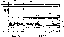
Figure 1A-1E represents view of the present invention;
Fig. 2 represents the curve chart of the roughness root mean square (rms) that obtains by AFM;
Fig. 3 represents the P-V value curve chart that obtains by AFM;
Fig. 4 A-4F represents the view of the present invention's (embodiment 1) manufacturing step;
Fig. 5 A-5D represents the view of the present invention's's (embodiment 1) manufacturing step;
Fig. 6 A-6D represents the view of the manufacturing step of active matrix substrate (embodiment 2);
Fig. 7 A-7C represents the view of the manufacturing step of active matrix substrate (embodiment 2);
Fig. 8 represents the view of active matrix substrate (embodiment 2);
Fig. 9 represents the external view of AM-LCD (embodiment 3);
Figure 10 represents the example of part LCD (embodiment 4);
Figure 11 A and 11B represent vertical view and its cross sectional view (embodiment 5) of EL module respectively;
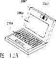
Figure 12 A-12F represents the example of electronic equipment (embodiment 6) respectively;
Figure 13 A-13D represents the example of electronic equipment (embodiment 6) respectively;
Figure 14 A-14C represents the example of electronic equipment (embodiment 6) respectively; With
Figure 15 A-15C is the microphoto on expression germanium-silicon film and silicon fiml surface.
Embodiment
[execution mode]
Below with reference to Figure 1A-1E embodiments of the present invention are described.
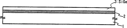
At first, on insulating surface, form the amorphous semiconductor film 3 that contains germanium.For example, on quartz substrate or glass substrate, form underlying insulation film.Herein, dielectric film mainly contains silicon, and silicon oxide film, silicon nitride film or oxynitride film or its sandwich that forms on glass substrate 1 for example is as underlying insulation film 2 (Figure 1A).It is to be noted that it is in order to prevent the diffusion of impurities from substrate that underlying insulation film 2 is set, and in some cases, according to the substrate that will use, is not especially this film to be set.
Form the amorphous semiconductor film 3 that contains germanium by pdp body CVD method, low pressure chemical vapor deposition method or other suitable methods.When using pdp body CVD method, in reaction chamber, introduce SiH
4And GeH
4The reacting gas that constitutes, and the optional SiH that uses
4And H
2Dilution GeH
4The reactant gas that constitutes to carry out the high-frequency discharge that frequency is 1-200MHz, is used to decompose, thus deposition amorphous semiconductor film on substrate.As for reacting gas, can use Si respectively
2H
6Or SiF
4And GeF
4Replace SiH
4And GeH
4And, under the situation of using the low pressure chemical vapor deposition method, can adopt this reacting gas.Preferably, reacting gas dilutes with He, deposits the amorphous semiconductor film under 400-500 ℃ temperature on substrate.Under any circumstance, employed above-mentioned gas is purified to high-purity among the present invention, and to reduce for example concentration of oxygen, nitrogen or carbon of impurity element, they can be received in the amorphous semiconductor film of deposition.It is to be noted that the thickness of the amorphous semiconductor film of deposition is set to 20-100nm.
Make the amorphous semiconductor membrane crystallization (Figure 1B) that contains germanium by heat treatment then.In order to contain the amorphous semiconductor membrane crystallization of germanium, must at 600 ℃ or higher temperature be heat-treated 10 hours or the longer time.
Use laser radiation with the raising crystallization rate then, and repair the defective (Fig. 1 C) that is retained in the crystal grain.When the amorphous semiconductor film that does not contain germanium applies laser, form big inhomogeneous on its surface.On the other hand, when when the amorphous semiconductor film that contains germanium applies laser, although form inhomogeneously equally, it is enough little and kept the smooth of surface.
For shining, use wavelength to be 400nm or littler excimer laser or YAG laser or YVO with laser
4The second harmonic of laser (wavelength 532nm) to the 4th harmonic wave (wavelength 266nm) as light source.Above-mentioned laser is converged to linearity or point-like by optical system, is set at 100-700mJ/cm with it
2Energy density shine, therefore this process is to assemble in the presumptive area of substrate by scanning laser beam to carry out.
It is to be noted, be that example is described with the pulse laser herein, but can use continuous oscillation type laser.Preferably, for the crystal that obtains to have big crystallite dimension through the amorphous silicon membrane crystallization, solid state laser that can continuous oscillation combines with second harmonic to the four-time harmonic that applies first-harmonic.In general, can use Nd:YVO
4The second harmonic (wavelength 532nm) of laser (first-harmonic 1064nm) or third harmonic (wavelength 355nm).When using continuous oscillation type laser, from continuous oscillation type YVO
4Laser sends the laser that is output as 10W and is changed into harmonic wave by nonlinear optical element.A kind of method is arranged, wherein YVO herein,
4Crystal and nonlinear optical element are placed in the resonator to send harmonic wave.Then, preferably, on irradiating surface, form rectangle or oval-shaped laser, want processed parts to be applied to by optical system.At this moment, required energy density roughly is 0.01-100MW/cm
2(0.1-10MW/cm preferably
2).Semiconductor film can be shone according to the mode that the speed of 10-2000cm/s roughly moves with respect to laser beam.
In addition, as the replacement of laser, can use halogen lamp, xenon lamp, mercury lamp, metal halide lamp etc. as light source.
Consider the productive rate of TFT, above-mentioned heat treatment is not all to be fit to all the time, thereby the crystallization of amorphous silicon film can be only by laser (impulse hunting type excimer laser or continuous oscillation type laser (YVO
4Second harmonic)) irradiation and carry out.And can use the technology that in JP07-130652A or JP08-78329A, discloses, wherein introduced metallic element and quickened the crystallization of silicon, by obtaining crystal silicon film being lower than to heat-treat under the temperature of normal conditions.
In addition, in order further to improve evenness, can be after above-mentioned laser radiation, adopt rare hydrofluoric acid etc. to remove the oxidation film (not shown) that laser radiation produces, with once more in inert atmosphere or apply laser (energy density is higher than the laser that last time applied) in a vacuum.
Then, adopt known formation method of patterning, smooth semiconductor film is formed pattern, have the semiconductor layer 6 (Fig. 1 D) of required form with formation.Hope formed thin oxidation film with Ozone Water in its surface before the mask that the formation resist is made.
With the surface of the etchant washing semi-conductor layer that contains hydrofluoric acid,, be used as gate insulating film 7 then to form main siliceous dielectric film.The washing on hope surface and the formation of gate insulating film are carried out continuously, are not exposed to outside air.
Wash the surface of gate insulating film 7 then, therefore form gate electrode 8.Suitably add then and give the impurity element (for example P or As) of semiconductor (being phosphorous in this case), to form source region 9 and drain region 10 with n type conductivity.After adding, heat-treat, strong illumination or laser radiation, be used for the activated impurity element.And in activation, impose on the plasma damage of gate insulating film or be applied to gate insulating film and semiconductor layer between at the interface plasma damage can be resumed.Especially, with the second harmonic of YAG laser in room temperature to 300 ℃ atmosphere in the past or to apply with the activated impurity element be very effective in the back.With regard to the viewpoint of less maintenance, the YAG laser is preferred activation equipment.
Later step is as follows: form intermediate insulating film 12, carry out hydrogenation, form the contact hole in sensible source region and drain region, form source electrode 13 and drain electrode 14, to finish TFT (n passage TFT) (Fig. 1 E).
So the passage of the TFT that the obtains surface that forms district 11 can have less than the roughness root mean square (rms) of 10nm and less than the P-V value of 70nm.
The invention is not restricted to the TFT structure shown in Fig. 1 E, can adopt LDD structure (drain structure of light dope), wherein the LDD district is clipped between passage formation district and drain region (or source region) as required.This structure is that the district that wherein is added with the low concentration impurity element is set between the passage formation district and source region or drain region that forms with high concentration adding impurity element.This district is called as the LDD district.In addition, can adopt so-called GOLD (LDD that grid-leakage is overlapping) structure, wherein the LDD district is configured to the overlapping gate electrode by gate insulating film.
Adopt n passage TFT to be described herein, but need not explanation, p passage TFT can adopt p type impurity element to replace n type impurity element and form.
And this sentences top gate type TFT is that example is described, but can adopt the present invention and need not to consider that TFT structure, the present invention can be used for for example bottom gate type (reverse irregular type) TFT or the irregular type TFT of forward.
Experiment
Carry out following experiment.
On glass substrate, form basilar memebrane.This underlying insulation film is made of double-decker, comprises that thickness is first oxygen silicon nitride membrane of 50-100nm, and it is to adopt SiH
4, NH
3And N
2O forms as reaction gas, and comprises that thickness is second oxygen silicon nitride membrane of 100-150nm, and it is to adopt SiH
4And N
2O forms as reaction gas, and this two membranes is by lamination.
After forming underlying insulation film, form the amorphous semiconductor film then.As the amorphous semiconductor film, form amorphous silicon film, contain the amorphous silicon film of 1.7% germanium and the amorphous silicon film that contains 3.5% germanium with respect to silicon by the plasma CVD method respectively with respect to silicon.
Next, apply by spin coater that to contain weight ratio concentration be that the nickel acetate solution of the nickel of 10ppm forms and contains nickel dam.Handle 500 ℃ of dehydrogenations of carrying out 1 hour then, to reduce the hydrogen concentration in the film, then 550 ℃ of heat treatments of carrying out 4 hours, to form the semiconductor film that contains crystalline texture respectively.
At this moment, embodiment as a comparison measures the surface condition of each semiconductor film by atomic force microscopy (AFM).Measurement result is shown in Fig. 2 and 3.The root mean square (rms) of Fig. 2 presentation surface inequality degree, Fig. 3 are represented peak-paddy (P-V) value (difference in height between maximum and the minimum value) of uneven degree.Fig. 2 and 3 value all are to measure in the zone of 3 μ m * 3 μ m herein.
In order to improve crystalline rate and to repair defective residual in crystal grain, radiation laser (XeCl: wavelength 308nm) in atmosphere or oxygen again.As laser, use excimer laser (wavelength 400nm or littler), and the second harmonic of YAG laser or third harmonic.Under any circumstance, use pulse laser, and this laser convergence is become 100-500mJ/cm by optical system with the repetition rate that is roughly 10-1000Hz
2, apply with the overlapping ratio of 90-95% and scan the silicon fiml surface.
When changing the energy density condition, irradiating laser also adopts AFM to measure to each condition.Measurement result is shown in Fig. 2 and 3.
Can clearly be seen that from Fig. 2 and 3 along with the increase of Ge content, the uneven degree on surface diminishes.Specifically, surface roughness root mean square (rms) and P-V value reduce, and have improved surperficial evenness.
About roughness root mean square (rms), with laser radiation after, the value of not germanic silicon fiml approximately is 10-30nm, and in containing the film of germanium, lip-deep uneven degree root mean square (rms) is suppressed to less than 10nm.
About the P-V value, with laser radiation after, the value of not germanic silicon fiml approximately is 70-100nm, and in containing the film of germanium, lip-deep uneven degree P-V value is suppressed to less than 70nm.
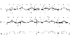
Figure 15 A-15C is shining the microphoto of the situation of film with laser in atmosphere herein, and wherein camera lens (shot) is set at 13, and repetition rate is set at 30Hz, and energy density is set at 521mJ/cm
2Figure 15 A represents the situation (Si of germanium-silicon film
1-XGe
X(X=0.017)), Figure 15 B represents the situation (Si of germanium-silicon film
1-XGe
X(X=0.035)), Figure 15 C represents the situation of silicon fiml.As can be seen, compare (Figure 15 C) with not germanic semiconductor film from microphoto, contain semiconductor film (Figure 15 A and 15B) the evenness height of germanium, uneven degree is little.
In addition, the semiconductor film that obtains according to said method is with respect to { the 101} crystal face has high orientation ratio.As for the orientation ratio of crystal, crystal grain is mainly to { 101} high preferred orientation, and can observe crystal grain and tend to { the 311} planar orientation should { the 311} face be positioned at { 001} plane and { 111} plane position intermediate.Specifically, the 101} crystal face, the 001} plane or in the 111} plane, its angle with respect to semiconductor layer surface be the ratio of 10 ° or lower crystal grain be respectively 20% or bigger, 3% or littler and 5% or littler.
By the distribution of electron back to diffraction (backscatter diffraction) pattern (EBSP) acquisition crystal orientation, this method is to carry out the method that crystal orientation is analyzed with the specific detectors that is arranged on scanning electron microscopy (SEM) from the backscattering of primary electron.By repeating orientation analysis in the position that is applied in (mapping) electron beam at mobile example, can obtain the information on the orientation in crystal orientation or the plane sample.The width of incident beam changes according to the electron gun type of scanning electron microscopy, but under the situation of Schottky (Schottky) emission type, applies the quite thin electron beam of 10-20nm.In mapping (mapping),, can obtain further average information on the crystal orientation along with the increase of measurement point quantity or measured zone area.In fact, measure with 10000 points (1 μ m at interval) to 40000 points (0.5 μ m at interval) roughly in the zone of 100 μ m * 100 μ m.After determining the crystal orientation of each crystal grain fully, can add up the condition of grain orientation that show with respect to film by mapping.If this distribution concentrate near the 101} crystal face, and so in actual membrane each crystal grain<101 be oriented on the direction that is approximately perpendicular to substrate.At this moment, can guess the crystal grain setting thereabout, some fluctuations are arranged.The fluctuation angle is provided with an acceptable value, and for example 5 degree or 10 are spent, and angle shows with numerical value less than the ratio of the crystal grain of above-mentioned value.Herein, the acceptable deflecting angle is set to aforesaid 5 or 10 degree, and the ratio that angle falls into the crystal grain of this scope is called as the orientation rate of crystal.
The crystal silicon film that forms by conventional method is influenced by substrate or underlying insulation film when crystallization, deposits a plurality of crystal grain thus.Although therefore oriented the orientation on 111} plane, low towards the crystal grain ratio of the orientation of in-plane.
Evenness by using acquisition like this and the crystal semiconductor film that the orientation rate is high in semiconductor film be as the active layer of TFT, can obtain to have the semiconductor device of the low OFF current value of less variation.
Utilize following embodiment that said structure of the present invention is described in further detail.
[embodiment 1]
Figure 4 and 5 represent to carry out the example that TFT is made in twice laser radiation.
At first, by for example silicon oxide film, silicon nitride film or oxygen silicon nitride membrane (SiO
xN
y) dielectric film on substrate 20, form underlying insulation film 21, shown in Fig. 4 A.Typical case is that double-decker is as underlying insulation film 21.Adopt a kind of like this structure, wherein the first silicon oxynitride film thickness is 50-100nm, and it is to adopt SiH
4, NH
3And N
2O forms as reaction gas, and the second silicon oxynitride film thickness is 100-150nm, and it is to adopt SiH
4And N
2O forms as reaction gas, and this two membranes is by lamination.In addition, preferably use thickness to be 10nmg or the littler silicon nitride film (SiN film) or the second oxygen silicon nitride membrane (SiO
xN
y, wherein X>>Y) as one deck of underlying insulation film 21.Nickel has and is easy to move to the zone that comprises high concentration oxygen, and therefore using the silicon nitride film that contacts with semiconductor film is very effectively as underlying insulation film.In addition, also can use three-decker, wherein first oxygen silicon nitride membrane, second oxygen silicon nitride membrane and silicon nitride film quilt are according to described order lamination.
On underlying insulation film, form first semiconductor film 22 of the impalpable structure that contains germanium then.Generally use the film of for example amorphous SiGe film, form the thickness of 10-100nm by plasma CVD, decompression CVD or sputter.Preferably the impurity that will in first semiconductor film 22, contain for example the concentration of oxygen and nitrogen be reduced to 5 * 10
18/ cm
3Or lower (adopt secondary ion mass spectrometry measure atomic concentration (SIMS)), obtain to have the semiconductor film of satisfied crystal structure with crystallization by the back.These impurity elements have caused the interference to the crystallization of back, and make that the concentration of trap center and complex centre increases after the crystallization.Therefore hope is used and is had highly purified material gas, and adopts ultra high vacuum CVD equipment, and wherein its reaction chamber is inner by process mirror process (electrobrightening), and is provided with no oily pumped vacuum systems.
Adopt JP patent application special permission to disclose among the flat 8-78329 disclosed method then and carry out crystallization as the method for first semiconductor film, 22 crystallizations.The method that discloses among the flat 8-78329 in Japanese patent application is that the selectivity adding is used to promote the metallic element of crystallization in amorphous silicon film, and heat-treats.So form semiconductor film, it has the crystal structure that launches from the zone that has added metallic element.At first, apply the nickel acetate solution that contains the metallic element that weight ratio is 1-100ppm (being nickel) herein by spinner to the surface of first semiconductor film 22, contain nickel dam 23 (seeing Fig. 4 B) with formation, wherein this metallic element has the catalyst function that promotes crystallization.Can adopt the method that forms extremely thin film by sputter, evaporation or plasma treatment, contain the additive method of nickel dam 23 as formation.In addition, although shown the example that on whole surface, applies herein, can optionally form by forming mask and contain nickel dam.
Heat-treat after the crystallization.In this case, form silicide, utilize silicide to quicken crystallization then as nuclear in semiconductor film and the contacted part of the metallic element that promotes semiconducting crystal.Shown in Fig. 4 C, so form the first semiconductor film 24a with crystalline texture.It is to be noted, wish that the oxygen concentration that contains among the first semiconductor film 24a is 5 * 10 after crystallization
18/ cm
3Or it is littler.450 ℃ of dehydrogenation heat treatments of carrying out 1 hour, handle 550-650 ℃ of crystallization heat of carrying out 4-24 hour then.In addition, the irradiation high light with the situation of carrying out crystallization under, can use one or more that are selected from infrared light, visible light and ultraviolet light.The general light that sends from halogen lamp, metal halide lamp, xenon arc lamp, carbon arc lamp, high-pressure sodium lamp or high-pressure mercury lamp that uses.The light source of lamp can be opened 1-60 second, and preferably 30-60 second, this operation can repeat 1-10 time, with the instantaneous order of magnitude that is heated to 600-1000 ℃ of semiconductor film.It is to be noted, if desired, can be in the heat treatment of the effusion of the hydrogen during irradiation make the first semiconductor film 24a that comprises before the high light.In addition, can adopt the method for heat treatment and irradiation high light to carry out crystallization simultaneously.Consider productive rate, preferably adopt strong illumination and carry out crystallization.
Metallic element (herein being nickel) is retained among the first semiconductor film 24a of formation like this.Although metallic element is not equally distributed in whole film, average residual concentration surpasses 1 * 10
19/ cm
3Even also certainly form various types of semiconductor elements in this state, as TFT.But following description is removed metallic element by air-breathing method.
Then to the irradiating laser (first laser) in atmosphere or oxygen of the first semiconductor film 24a with crystal, to improve degree of crystallinity (crystalline component is with respect to the ratio of total membrane volume) and to repair the defective that keeps in the crystal grain.If irradiating laser forms inequality in the surface, and forms thin oxidation film 25 (seeing Fig. 4 D).Employed laser (first laser) is excimer laser, and wavelength is 400nm or littler, or the second harmonic of YAG laser or triple-frequency harmonics.In addition, the light that sends from ultraviolet lamp can be as the replacement of excimer laser.Under any circumstance, use repetition rate to be roughly the pulse laser of 10-1000Hz, this pulse laser is converged to 100-500mJ/cm by optical system
2, shine with the Duplication of 90-95%, can scan the silicon fiml surface thus.
Then, remove oxidation film 25 (Fig. 1 E).First semiconductor film that in nitrogen or vacuum, has crystal structure then with laser (second laser) irradiation.When irradiation during second laser, be reduced by P-V value (peak-valley: the maximum highly and the difference of minimum value) and the rms that shines the uneven degree that first laser forms.Promptly carry out semiconductor film 24b smooth (Fig. 1 F).Employed laser (second laser) is excimer laser, and wavelength is 400nm or littler, or the second harmonic of YAG laser and triple-frequency harmonics.In addition, the light that sends from ultraviolet lamp can be as the replacement of excimer laser.It is to be noted that the energy density of second laser is bigger than the energy density of first laser, preferred big 30-60mJ/cm
2
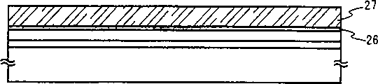
In addition, forming oxidation film (being called the chemical oxide film) by using the aqueous solution ozoniferous (normally Ozone Water), is the oxidation film barrier layer 26 of 1-10nm to form gross thickness.On barrier layer 26, form second semiconductor film 27 (Fig. 5 A) that contains inert gas elements then.The effect of etching stopper is played on barrier layer 26 when a selectivity of back is removed second semiconductor film 106.In addition, can similarly form chemical oxide by the water solution-treated, as the substrate of the aqueous solution that is used to contain ozone, the sour mixed aqueous hydrogen peroxide solution of sulfuric acid, hydrochloric acid or nitric acid for example in this aqueous solution.Also can use other method to form barrier layer 26, wherein produce ozone, and oxidation have the surface of the semiconductor film of crystal structure by irradiating ultraviolet light in oxygen.In addition, can utilize as the method for plasma CVD, sputter or evaporation and be deposited as the barrier layer with thick for the oxidation film of 1-10nm magnitude as the additive method that forms barrier layer 26.In addition, can under the temperature of 200-350 ℃ of magnitude, heat and form thin oxidation film with the cleaning stove, as the another kind of method on formation barrier layer 26.It is to be noted, the method that forms barrier layer 26 is had no particular limits, as long as can by a kind of in the said method or it is in conjunction with forming.But film quality that barrier layer 26 must have or thin and thick should be the nickel that makes in first semiconductor film and can move in second semiconductor film by the air-breathing of back.
Herein, second semiconductor film 27 that contains inert gas elements forms by sputter, to form suction location.It is to be noted that sputtering condition is preferably by suitable adjustment, so that inert gas elements is not added in first semiconductor film.One or more elements that are selected from helium (He), neon (Ne), argon (Ar), krypton (Kr) and xenon (Xe) are used as inert gas elements.In these elements, preferably use argon (Ar), it is low-cost gas.This is in and uses silicon target to form second semiconductor film in the atmosphere that contains inert gas elements.About being that the method that the ion packet of inert gas is contained in the film has two kinds with the rare gas element: a kind of is to form unsaturated bond to give semiconductor film with distortion, and another kind is to form distortion in the lattice of semiconductor film.Have the element bigger than the atomic radius of silicon if use, for example argon (Ar), krypton (Kr) or xenon (Xe) just can significantly obtain the distortion in the semiconductor film lattice.Be not only by in film, comprising the lattice distortion that the rare gas element forms, also form azygous key and help air-breathing reaction.
In addition, form under the situation of second semiconductor film at the target that adopts phosphorous (impurity element) with single conductivity type, except carry out with the rare gas element air-breathing, the Coulomb force of employing phosphorus is carried out air-breathing.
Heat-treat after air-breathing, from first semiconductor film, remove (Fig. 5 B) with the concentration that reduces the metallic element (nickel) in first semiconductor film or with it.Can carry out strong illumination processing or heat treatment and be used as heat treated.Metallic element moves (promptly in the direction from the substrate side second semiconductor film surface) in the direction of arrow shown in Fig. 5 B, be blocked metallic element that contains among the layer 26 first semiconductor film 24b that is covered or the concentration that reduces this metallic element to remove.The distance that metallic element moves in breathing process can be at least the first other distance of semiconductor film thickness level, therefore can finish air-breathing with the short relatively time.Carry out fully air-breathingly, and can not be isolated among the first semiconductor film 24b so that all nickel moves to second semiconductor film 27, therefore in the first semiconductor film 24b contained Ni-based do not exist.Thereby the concentration of promptly carrying out the nickel in air-breathing first semiconductor film becomes and is equal to or less than 1 * 10
18/ cm
3, preferably be equal to or less than 1 * 10
17/ cm
3
In this manual, the air-breathing metallic element that is meant is from will being distributed because of heat energy by air-breathing zone (being first semiconductor film) herein, and metallic element moves to moving of suction location because of diffusion.Therefore, the air-breathing processing temperature that depends on is along with rising processing time of temperature shortens.
In addition, the method that adopts strong illumination as air-breathing heat treated situation under, the light source of the lamp that is used to heat is opened 1-60 second, preferably 30-60 second, this operation repeats preferably 2-6 time 1-10 time.Although the luminous intensity of light source can be set arbitrarily, semiconductor film will be heated to 600-1000 ℃ by instantaneous, preferably 700-750 ℃.
Under the situation of heat-treating, can be 450-800 ℃ of heating 1-24 hour in nitrogen, for example 550 ℃ of heating 14 hours.Except heat treatment, can shine high light.
Then, utilize barrier layer 26 only optionally to remove second semiconductor film, also remove the barrier layer that oxidation film 26 forms as the etching stopper.Can not utilize ClF
3The dry etching of plasma perhaps adopts for example hydrazine or contain tetraethyl ammonium hydroxide (chemical formula is (CH of aqueous slkali
3)
4The wet etching of the aqueous solution NOH) is as the method for optionally only removing second semiconductor film.In addition, preferably after removing second semiconductor film, remove the barrier layer, because by measuring nickel concentration has detected high concentration on the surface on barrier layer nickel with TXRF.The etchant that utilization contains hydrofluoric acid is removed the barrier layer.
Utilize known formation method of patterning smooth semiconductor film 24b to be formed semiconductor layer 28 (Fig. 5 C) then with ideal form.Preferred from the teeth outwards by adopting Ozone Water before forming the resist mask, to form thin oxidation film.
Then after the etchant that employing contains hydrofluoric acid has cleaned the surface of semiconductor film, form and comprise the dielectric film that become gate insulating film 29 of silicon as main component.The cleaning of preferred surface and the formation of gate insulating film are continuous, and can not be exposed in the atmosphere.
Then according to the embodiment of the present invention pattern in same method carry out the step of back, to form TFT (Fig. 5 D).It is to be noted that Reference numeral 29-36 represents that respectively gate insulating film, gate electrode, source region, drain region, passage form district, source electrode, drain electrode and insulating film of intermediate layer.
In addition, this embodiment can combine freely with embodiment of the present invention pattern.In addition, the present embodiment also can with other known air-breathing method combinations.
In addition, following situation also is fine: by air-breathing semiconductor layer is formed reservation shape, after removing oxidation film, carry out the irradiation of second laser in inert atmosphere or vacuum then, smooth to carry out, and do not carry out the irradiation of second laser before air-breathing.
[embodiment 2]
Below with reference to Fig. 6-8 one embodiment of the invention are described.Describe the method for on same substrate, making pixel portion simultaneously and being arranged on the TFT (n passage TFT and p passage TFT) in pixel portion driving loop on every side in detail herein.
At first, on substrate 100, form underlying insulation film 101, obtain to have first semiconductor film of crystal structure.Then semiconductor film is etched into desired shapes to form the semiconductor layer 102-106 that is separated from each other of island.
Use glass substrate (#1737) as substrate 100.For underlying insulation film 101, using plasma CVD method forms with SiH at 400 ℃ film deposition temperature
4, NH
3And N
2O as unstripped gas (ratio of components is Si=32%, O=27%, N=24%, H=17%) the oxygen silicon nitride membrane 101a of Xing Chenging, its thickness are 50nm (being preferably 10-200nm).Cleaned after the surface with Ozone Water then, utilized diluted hydrofluoric acid (dilution is 1/100) to remove lip-deep oxidation film.Using plasma CVD method forms with SiH at 400 ℃ film deposition temperature then
4And N
2O as unstripped gas (ratio of components is Si=32%, O=59%, N=7%, H=2%) the oxygen silicon nitride membrane 101b of the hydrogenation of Xing Chenging, its thickness is 100nm (being preferably 50-200nm), forms the stratiform thing thus.Under the situation that is not exposed to atmosphere, use SiH in addition
4As the film deposition gases, using plasma CVD method forms the semiconductor film (being amorphous silicon film in this case) with impalpable structure at 300 ℃ film deposition temperature, and thickness is 54nm (preferably 25-80nm).And can use Si
2H
6Or SiF
4Replace SiH
4, use GeF
4Replace GeH
4
In this embodiment, basilar memebrane 101 is shown as double-decker, but can adopt the individual layer dielectric film or wherein lamination two-layer or more multi-layered structure.In addition, without limits to the semiconductor film material.But this semiconductor film is preferably by silicon or SiGe (Si
XGe
1-X(X=0.0001-0.02) alloy adopts known method (sputter, LPCVD, plasma CVD etc.) to form.In addition, plasma CVD apparatus can be single wafer type or batch-type.In addition, underlying insulation film and semiconductor film can form in the chamber at same film and form continuously under the environment that is not exposed to atmosphere.
Then, after the semiconductor film surface with impalpable structure is cleaned, form the extremely thin oxidation film that thickness is about 2nm by Ozone Water on the surface.In order to control the threshold values of TFT, carry out the doping of micro impurity element (boron or phosphorus) then.Adopt ion doping method, wherein diborane (B herein,
2H
6) by plasma exciatiaon rather than mass separation, under following doping condition, boron is joined in the amorphous silicon film: accelerating voltage 15KV; With hydrogen dilution is that 1% diborane gas flow velocity is 30sccm; Dosage is 2 * 10
12/ cm
2
Contain the nickel acetate salting liquid that weight ratio is the nickel of 10ppm with the spinner coating then.As the replacement of coating, can adopt the method for spraying nickel element to whole surface by sputter.
Heat-treat then to carry out crystallization, form semiconductor film thus with crystal structure.Adopt the heating means of electric furnace or strong illumination can be used for heat treatment.Under the situation that adopts electric furnace to heat, can carry out 4-24 hour at 500-650 ℃., in the heat treatment of having carried out dehydrogenation (550 ℃ 1 hour) afterwards, be used for the hot working (550 ℃ 4 hours) of crystallization herein, obtain silicon fiml thus with crystalline texture.It is to be noted, carry out crystallization, also can adopt the method for lamp annealing to carry out crystallization although adopt the heating means of stove.And it is to be noted, adopt nickel method for crystallising as the metallic element that promote silicon crystallization although use herein, can use other known method for crystallising, for example adopt solid state growth method and laser crystal method.
Then, after the lip-deep oxidation film of the silicon fiml with crystalline texture is removed by diluted hydrofluoric acid etc., atmosphere or in oxygen irradiation first laser (XeCl: wavelength is 308nm), be used for improving crystallization rate and repair the defective that is retained in crystal grain.Use wavelength to be 400nm or littler excimer laser, or the second harmonic of YAG laser or third harmonic.Under any circumstance, use pulse laser, and this laser convergence is become 100-500mJ/cm by optical system with the repetition rate that is roughly 10-1000Hz
2, shine with the overlapping ratio of 90-95% and scan the silicon fiml surface.It is to be noted, form oxidation film from the teeth outwards, because irradiation forms in atmosphere or oxygen by first laser radiation.
Then, after the employing diluted hydrofluoric acid is removed the oxidation film of first laser radiation formation, in nitrogen or vacuum, carry out second laser radiation, thus the surface of smooth semiconductor film.Use wavelength to be 400nm or littler excimer laser, or the second harmonic of YAG laser or third harmonic are as laser (second laser).The energy density of second laser is bigger than first laser, preferred big 30-60mJ/cm
2
Then, 120 seconds processing is carried out on the surface, formed general thickness thus and be the barrier layer that constitutes by oxidation film of 1-5nm with Ozone Water.
Formation thickness is the amorphous silicon film that contains the argon element of 150nm on the barrier layer by sputtering at, and this argon element becomes suction location.The film sedimentary condition of sputter in this embodiment is: the film deposition pressure is 0.3Pa, and gas (argon) flow velocity is 50sccm, and the film deposition power is 3KW, and underlayer temperature is 150 ℃.It is to be noted that under these conditions, the argon atoms of elements concentration that is contained is 3 * 10 in amorphous silicon film
20/ cm
3-6 * 10
20/ cm
3, the atomic concentration of oxygen is 1 * 10
19/ cm
3-3 * 10
19/ cm
3Adopt the lamp annealing device air-breathing to carry out then 650 ℃ of heat treatments of carrying out 3 minutes.
Subsequently, utilize the barrier layer optionally to remove the amorphous silicon film that contains argon element (it is a suction location), utilize diluted hydrofluoric acid optionally to remove the barrier layer then as the etching stopper.It is to be noted, have a kind of tendency, promptly nickel may move to the zone of hyperoxia concentration in air-breathing, so it is desirable to remove after air-breathing the barrier layer that is made of oxidation film.
Then, after forming thin-oxide film on the silicon fiml with crystal structure (the being also referred to as polysilicon film) surface that is being obtained by Ozone Water, form the resist mask, it is etched with the acquisition desired shapes, form the island semiconductor layer 102-106 that is separated from each other thus.After semiconductor layer forms, remove the mask that resist is made.
Utilize the etchant that contains hydrofluoric acid to remove oxidation film then, clean the surface of silicon fiml simultaneously.Form then and contain the dielectric film of silicon as main component, it becomes gate insulating film 107.In this embodiment, by plasma CVD form the oxygen silicon nitride membrane that thickness is 115nm (proportion of composing: Si=32%, O=59%, N=7%, H=2%).
Then as shown in Figure 6A, on gate insulating film 107, be that the first conducting film 108a of 20-100nm and the second conducting film 108b that thickness is 100-400nm form lamina with thickness.In this embodiment, nitrogenize tantalum film that stacked above one another 50nm is thick on gate insulating film 107 and the thick tungsten film of 370nm.
As the electric conducting material that forms first conducting film and second conducting film, adopt to be selected from the element of Ta, W, Ti, Mo, Al and Cu or to contain alloy material or the compound-material of above-mentioned element as main component.In addition, for example the polysilicon film of phosphorus or the semiconductor film that the AgPdCu alloy is representative can be used as first conducting film and second conducting film with the impurity element that mixed.In addition, the invention is not restricted to double-decker.For example can adopt three-decker, wherein the tungsten film that 50nm is thick, thickness are that the thick titanium nitride film of the Al of 500nm and the alloy of Si (Al-Si) film and 30nm is by stacked above one another.In addition, under the situation of three-decker, tungsten nitride can be used for replacing the tungsten of first conducting film, and the alloy film of aluminium and titanium (Al-Ti) can be used for replacing the Al of second conducting film and the alloy of Si (Al-Si) film, and titanium film can be used to replace the titanium nitride film of the 3rd conducting film.In addition, can adopt single layer structure.
Then, shown in Fig. 6 B, form mask 110-115, carry out first etching process to form gate electrode and lead by step of exposure.Under first and second etching conditions, carry out first etching process.Preferred ICP (inductively coupled plasma) method that adopts is carried out etching.Adopt the ICP engraving method, and suitable adjustment etching condition (putting on the temperature etc. of the electrode of the electric energy of the electrode of coil shape, the electric energy that is applied to the electrode of substrate side, substrate side), can come etching-film according to desirable taper thus.It is to be noted that employing that can be suitable is with Cl
2, BCl
3, SiCl
4And CCl
4For the representative the chloro-base gas, with CF
4, SF
6And NF
3Fluoro-base gas and O for representative
2As etching gas.
In this embodiment, also apply the RF power (13.56MHz) of 150W, to apply basic negativity self-bias voltage to substrate (sample stage).Under first etching condition, etching W film forms taper with the end with first conductive layer.Under first etching condition, be 200.39nm/min to the etch-rate of W, be 80.32nm/min to the etch-rate of TaN, W is about 2.5 to the selection ratio of TaN.In addition, under first etching condition, the coning angle of W approximately is 26 °.Then first etching condition is become second etching condition, and do not remove the mask 110-115 that resist is made.Adopt CF
4And Cl
2As etching gas, the flow velocity of gas is set at 30/30sccm, applies the RF power (13.56MHz) of 500W under the pressure of 1Pa to the electrode of coil shape, to produce plasma, carries out 30 seconds etching thus.Apply the RF power (13.56MHz) of 20W to substrate side (sample stage), to apply basic negativity self-bias voltage.Under second etching condition, wherein mixed CF
4And Cl
2, come etching W film and TaN film with identical degree.Under second etching condition, be 58.97nm/min to the etch-rate of W, be 66.43nm/min to the etch-rate of TaN.It is to be noted, etching period is increased 10-20%, can on gate insulating film, not stay remnants to carry out etching.
In above-mentioned first etching process, the shape of the mask that resist is made is suitable, because impose on the effect of the bias voltage of substrate side, the end of the end of first conductive layer and second conductive layer all is respectively taper thus.The angle of tapering part is set in 15-45 ° fully.
Therefore, formed the conductive layer 117-121 of first shape that constitutes by first conductive layer and second conductive layer (the first conductive layer 117a-121a and the second conductive layer 117b-121b) by first etching process.The dielectric film 107 that becomes gate insulating film about 10-20nm that is etched becomes gate insulating film 116, and wherein the zone that is covered by the first shape conductive layer 117-121 does not approach.
Then, carry out second etching process, and do not remove the mask that resist is made.Use SF herein,
6, Cl
2And O
2As etching gas, the flow velocity of gas is set to 24/12/24sccm, applies the RF power (13.56MHz) of 700W under the pressure of 1.3Pa to the electrode of coil shape, to produce plasma, carries out 25 seconds etching thus.Apply the RF power (13.56MHz) of 10W to substrate side (sample stage), to apply basic negativity self-bias voltage.Under second etching condition, etch-rate to W is 227.3nm/min, is 32.1nm/min to the etch-rate of TaN, and W is about 7.1 to the selection ratio of TaN, to the etch-rate as the SiON of dielectric film 116 is 33.7nm/min, and W is about 6.83 to the selection ratio of SiON.Adopting SF
6Under the situation as etching gas, with respect to the selection of dielectric film 116 than being high, as mentioned above.Therefore can suppress reducing of thickness.In this embodiment, the thickness of dielectric film 116 has only reduced about 8nm.
By second etching process, the coning angle of W becomes 70 °.By second etching process, form the second conductive layer 124b-129b.On the other hand, seldom etching first conductive layer becomes the first conductive layer 124a-129a (Fig. 6 C).It is to be noted that the size of the first conductive layer 124a-129a is basic identical with the first conductive layer 117a-122a.In fact, the width of first conductive layer can reduce about 0.3 μ m, promptly with before second etching process compares, and highway width has approximately reduced by 0.6 μ m.But the size of first conductive layer does not have to change substantially.
Remove the mask that resist is made then, the first doping process of carrying out then is to obtain the state shown in Fig. 6 D.Can implant by ion doping or ion and mix.With 1.5 * 10
14Atom/cm
2Dosage under the situation of the accelerating voltage of 60-100keV, mix.As the impurity element of giving n type conductivity, generally use phosphorus (P) or arsenic (As).In this case, first conductive layer and the second conductive layer 124-128 become the mask that stops the impurity element of giving n type conductivity, form the first impurity range 130-134 in self aligned mode.To the first impurity range 130-134 with 1 * 10
16/ cm
3To 1 * 10
17/ cm
3Concentration add and to give the impurity element of n type conductivity.Herein, the zone that has with the first extrinsic region same concentrations scope is also referred to as n
-The district.
It is to be noted,, can not remove the mask that resist makes and just carry out the first doping process although after removing the mask that resist makes, carry out the first doping process in this embodiment.
Then, shown in Fig. 7 A, form the mask 135-137 that resist is made, carry out the second doping process.Mask 135 is to be used to protect the passage of the semiconductor layer that forms drive circuit p passage TFT to form district and its periphery; mask 136 is used to protect the passage of the semiconductor layer that forms drive circuit n passage TFT to form district and its periphery, and mask 137 is to be used to protect the passage of the semiconductor layer that forms pixel portion TFT to form district, its periphery and holding capacitor.
Under the ion doping condition of the second doping process: 1.5 * 10
15Atom/cm
2Dosage, the accelerating voltage of 60-100keV, Doping Phosphorus (P).In semiconductor layer separately, form impurity range as mask with the second conductive layer 124b-126b in self aligned mode herein.Certainly, do not add phosphorus to the zone that is covered by mask 135-137.Therefore form the second impurity range 138-140 and the 3rd impurity range 142.To the second impurity range 138-140 with 1 * 10
20/ cm
3To 1 * 10
21/ cm
3Concentration range add and to give the impurity element of n type conductivity.Herein, the zone that has with the second extrinsic region same concentrations scope is also referred to as n
+The district.
In addition, form the 3rd impurity range with low concentration than second impurity range by first conductive layer, and with 1 * 10
18/ cm
3To 1 * 10
19/ cm
3Concentration range add and to give the impurity element of n type conductivity.It is to be noted that owing to mix by the part with taper through first conductive layer, therefore the 3rd impurity range has concentration gradient, wherein the concentration of impurity increases towards the end direction of tapering part.Herein, the zone that has with the 3rd extrinsic region same concentrations scope is also referred to as n
-The district.In addition, in the second doping process, the zone that is covered by mask 136-137 is not added into impurity element, becomes first impurity range 144 and 145.
After having removed the mask 135-137 that resist makes, newly form the mask 146-148 that resist is made then, carry out the 3rd doping process shown in Fig. 7 B.
In actuator loop, by above-mentioned the 3rd doping process, form the 4th impurity range 149,150 and the 5th impurity range 151,152, wherein add and give the impurity element of p type conductivity to the semiconductor layer that forms p passage TFT and to the semiconductor layer that forms holding capacitor.
In addition, to the 4th impurity range 149 and 150 with 1 * 10
20/ cm
3To 1 * 10
21/ cm
3Concentration range add and to give the impurity element of p type conductivity.It is to be noted, at the 4th impurity range 149,150, at abovementioned steps (n
-The district) added phosphorus (P) in, given the impurity element of p type conductivity but can add according to the 1.5-3 concentration doubly of phosphorus.Therefore the 4th impurity range 149,150 has p type conductivity.Herein, the zone that has a same concentrations scope with the 4th impurity range is also referred to as p
+The district.
In addition, form the 5th impurity range 151 and 152 in tapering part overlapping areas with the second conductive layer 125a, and with 1 * 10
18/ cm
3To 1 * 10
20/ cm
3Concentration add and to give the impurity element of p type conductivity.Herein, the zone that has a same concentrations scope with the 5th impurity range is also referred to as p
-The district.
By above-mentioned steps, in semiconductor layer separately, form impurity range with n type or p type conductivity.Conductive layer 124-127 becomes the gate electrode of TFT.In addition, conductive layer 128 becomes one of electrode, and it forms the holding capacitor in the pixel portion.In addition, conductive layer 129 forms the interior source lead of pixel region.
Form the basic dielectric film (not shown) that covers whole surface then.In this embodiment, form the thick silicon oxide film of 50nm by plasma CVD.Certainly, dielectric film is not limited to silicon oxide film, can use other dielectric films that contain silicon with individual layer or stacked structure.
Then the impurity element that joins in the semiconductor layer is separately activated.In this activation step, the light that uses rapid thermal annealing (RTA) method utilized lamp source, sends from back side radiation YAG laser or excimer laser, the heat treatment of adopting stove or its in conjunction with etc.
In addition, although described the example that before activation, forms dielectric film, can after activation, carry out dielectric film and form step in this embodiment.
Then, form first intermediate insulating film 153, heat-treat (300-550 ℃ following 1-12 hour), carry out the hydrogenation (Fig. 7 C) of semiconductor layer thus by silicon nitride film.This step is the step that stops the dangling bonds of semiconductor layer by the hydrogen that is contained at first intermediate insulating film 153.Semiconductor layer can be hydrogenated, and irrelevant with the existence of the film formed dielectric film (not shown) of silica.Carry one in passing, in this embodiment, contain aluminium and be used as second conductive layer as the material of its main component, therefore the heat-treat condition that is importantly adopted in step of hydrogenation is that second conductive layer can bear.As the another kind of method of hydrogenation, can carry out plasma hydrogenation (hydrogen that using plasma excites).
Then, on first intermediate insulating film 153, form second intermediate insulating film 154 by organic insulating material.In this embodiment, forming thickness is the acrylic resin film of 1.6 μ m.Form the contact hole of sensible source lead 129, sensible conductive layer 127 and 128 contact hole respectively then, and the contact hole of sensible each impurity range.In this embodiment, carry out a plurality of etching processes in turn.In this embodiment, utilize first intermediate insulating film to come etching second intermediate insulating film, utilize the dielectric film (not shown) to come etching first intermediate insulating film, etching dielectric film (not shown) then as the etching stopper as the etching stopper.
After this, adopt Al, Ti, Mo, W etc. to form lead and pixel electrode.As the material of electrode and pixel electrode, it is desirable to use the material of reflecting properties excellence, for example contain Al or Ag as the film of its main component or the stacked film of above-mentioned film.Therefore form source electrode or drain electrode 155-160, grid lead 162, connection lead 161 and pixel electrode 163.
As mentioned above, can on same substrate, form the driving loop 206 with n passage TFT201, p passage TFT202 and n passage TFT203 and have pixel TFT 204 that n passage TFT constitutes and the pixel portion 207 (Fig. 8) of holding capacitor 205.In this manual, for for simplicity, above-mentioned substrate is called as the active matrix substrate.
In pixel portion 207, pixel TFT 204 (n passage TFT) has passage and forms district 167, forms first impurity range, the 145 (n outside the conductive layer 127 of gate electrode
--The district) and as the second impurity range (n in source region
+The district) 140.In addition, in semiconductor layer, form the 4th impurity range 150 and the 5th impurity range 152 as one of electrode of holding capacitor 205.Holding capacitor 205 constitutes as dielectric semiconductor layer 150,152 and 168 by second electrode 128 with dielectric film (film same with gate insulating film) 116.
In addition, in driving loop 206, n passage TFT201 (a n passage TFT) have passage form district 164, across the dielectric film three impurity range (n overlapping with the partially conductive floor 124 that forms gate electrode
-The district) 142 and as the second impurity range (n in source region or drain region
+The district) 138.
In addition, in driving loop 206, p passage TFT202 have passage form district 165, across the dielectric film five impurity range (p overlapping with the partially conductive floor 125 that forms gate electrode
-The district) 151 and as the 4th impurity range (p in source region or drain region
+The district) 149.
In addition, in driving loop 206, n passage TFT203 (the 2nd n passage TFT) have passage form district 166, across the dielectric film first impurity range (n overlapping with the partially conductive floor 126 that forms gate electrode
--The district) 144 and as the second impurity range (n in source region or drain region
+The district) 139.
Above-mentioned TFT201-203, is formed thus and drives loop 206 to form drift resistance loop (shift resistercircuit), buffer loop, level-shift loop, grid lock loop etc. by suitable combination.For example, under the situation that forms the CMOS loop, n passage TFT201 can complimentary to one anotherly be connected with p passage TFT202.
Especially, the structure of n passage TFT203 is suitable for having the buffer circuit of high driving voltage, to prevent the damage owing to hot carrier's effect.
In addition, be that the structure of the n passage TFT201 of GOLD structure is suitable for the prepreerence loop of reliability.
Evenness that the present invention obtains and the high semiconductor film of crystal orientation rate are formed the active layer as TFT, and voltage that TFT bore and reliability are enhanced thus.
In addition, described in this embodiment and to have made the example that the active matrix substrate is used for reflective display.If but form pixel electrode by nesa coating, although the quantity of photomask has increased by 1, can form transmissive display.
And this embodiment can freely combine with any embodiment pattern and embodiment 1.
[embodiment 3]
This embodiment has been described the process of being made active matrix liquid crystal display equipment in embodiment 2 by the active matrix substrate of making.Following description is with reference to figure 9.
After the active matrix substrate that obtains as shown in Figure 8 according to embodiment 2, on the active matrix substrate of Fig. 8, form alignment films, and carry out friction treatment.In this embodiment, before forming alignment films, to organic resin film for example acrylic resin film form pattern, to form the column separator, substrate is separated in desirable position.The column separator can be ejected at the whole lip-deep spherical separator of substrate and replace.
Prepare relative substrate then.This relative substrate has colour filter, and wherein nonferrous layer and light shield layer quilt is with respect to the pixel setting.Light shield layer also is set at the driving loop feature.Form polarizing coating to cover colour filter and light shield layer.On polarizing coating, form electrode of opposite by transparent conductive layer in pixel portion.On the whole surface of relative substrate, form alignment films and carry out friction treatment.
Adopt seal member that relative substrate binding is formed with pixel portion on it then and drive the active matrix substrate in loop.The sealing parts have the filler that is blended in wherein, and filler makes it keep distance together with the column separator when two substrate bindings together.Liquid crystal material is injected between two substrates, adopts the encapsulants (not shown) that substrate is sealed fully.Can use known liquid crystal material.Finished active matrix liquid crystal display thus.If desired, active matrix substrate or relative substrate are cut into the sheet of required form.Display can adopt known technology suitable be provided with polarization plates.Adopt known method that EPF is connected to substrate then.
So the structure of the Liquid Crystal Module that obtains is described below with reference to vertical view 9.
At the center of active matrix substrate 301 pixel portion 304 is set.On pixel portion 304, be provided for the source signal horizontal drive circuit 302 of drive source signal rows.Be provided with on the left side of pixel portion 304 and the right and be used to drive the capable gate signal horizontal drive circuit 302 of gate signal.Although gate signal horizontal drive circuit 303 is about pixel portion 304 symmetries in this embodiment, Liquid Crystal Module can have only a gate signal horizontal drive circuit on a side of pixel portion.In above-mentioned two options, the designer can select with regard to the substrate dimension of Liquid Crystal Module etc. and the layout that is fit to.But the symmetric configuration in the capable driving of the gate signal among Fig. 9 loop is preferred with regard to circuit operation reliability, driving efficient etc.
Signal is driven the loop from flexible print circuit (FPC) 305 inputs.Thereby in intermediate insulating film and resin molding, have contact hole and form in the sensible given position that is arranged on substrate 301 of connection electrode 309 lead capable after, FPC305 is by interference fits such as anisotropic conductive film.In this embodiment, connection electrode is formed by ITO.
The periphery around drive circuit and pixel portion along substrate applies sealant 307.By sealant 307 relative substrate 306 is bonded to substrate 301, remains the distance between two substrates (distance between substrate 301 and the substrate 306) constant at the separator that forms on the active matrix substrate in advance simultaneously.Liquid crystal cell is injected in the zone that is not coated with sealant 307 by substrate.With encapsulants 308 substrate is sealed then.Finished Liquid Crystal Module by above-mentioned steps.
Although all in an illustrated embodiment drive circuits are formed on the substrate, several IC can be used for some drive circuit.
In addition, this embodiment can freely combine with any structure in embodiment pattern, embodiment 1 and the embodiment 2.
[embodiment 4]
All the process with embodiment 2 is identical up to the manufacturing process of the step that forms intermediate insulating film, and it is described in this omission.After forming intermediate insulating film, form pixel electrode 601 by transparency conducting film according to embodiment 2.The example of transparency conducting film comprises ITO (indium tin oxide alloy) film, indium oxide-zinc oxide alloy (In
2O
3-ZnO) film, zinc oxide (ZnO) film etc.
In intermediate insulating film 600, form contact hole then.Form and the overlapping connection electrode 602 of pixel electrode again.Connection electrode 602 is connected to the drain region by contact hole.When forming connection electrode, form source electrode or the drain electrode of other TFT.
Although all in an illustrated embodiment drive circuits are formed on the substrate, several IC can be used for some drive circuit.
Finish the active matrix substrate as mentioned above.Form Liquid Crystal Module by this active matrix substrate according to embodiment 3.Liquid Crystal Module is provided with backlight 604 and light guide plate 605, and is covered by cover plate 606, and to finish active matrix liquid crystal display, its fragmentary sectional view as shown in figure 10.Cover plate is utilized adhesive or organic resin is bonded to Liquid Crystal Module.When with this substrate binding during to relative substrate, this substrate can be added with housing, thereby the space between frame and the substrate is filled with and is used for bonding organic resin.Because this display is a transmission-type, so the active matrix substrate all needs to be bonded with polarizer 603 respectively with relative substrate.
This embodiment can freely combine with any structure among embodiment pattern, the embodiment 1-3.
[embodiment 5]
In this embodiment, make the example of the active display that is provided with EL (electroluminescence) element shown in Figure 11 A and 11B.
Figure 11 A is the vertical view of EL module, and Figure 11 B is the cross sectional view along the A-A ' line of Figure 11 A.On the substrate 900 with insulating surface (for example glass substrate, glass ceramics substrate, plastic etc.), form pixel portion 902, source drive circuit 901, grid side drive circuit 903.Pixel portion and drive circuit can obtain according to above-mentioned embodiment.In addition, Reference numeral 918 expression seal members, Reference numeral 919 expression DLC films.The sealed parts 918 of pixel portion and driving circuit section cover, and the protected film 919 of sealing parts covers.In addition, diaphragm 919 is sealed by cover plate part 920 usefulness adhesives.It is desirable to, cover plate part 920 for example is a glass substrate by constituting with substrate 900 identical materials, can bear the distortion that heat or external force cause.Cover plate part 920 is processed into by sandblast etc. has spill (degree of depth is 3-10 μ m), shown in Figure 11 B.It is desirable to cover plate part 920 and also be processed to form sunk part (degree of depth is 50-200 μ m), wherein drier 921 can be set.Making under the situation of a plurality of EL modules in addition, after substrate and cover plate part are connected to each other, can adopt CO
2Lasers etc. are cut apart, thereby end face matches each other.
It is to be noted that Reference numeral 908 expression is used to transmit the lead of the signal of input source side drive circuit 901 and grid side drive circuit 903, and receive vision signal and clock signal from external input terminals FPC (flexible print circuit) 909.It is to be noted that although only shown FPC in the drawings, printed substrate (PWB) can be connected to FPC.Luminaire in this specification not only comprises the main body of luminaire, and comprises the luminaire that is connected with FPC or PWB.
Below with reference to Figure 11 B partial structurtes are described.Dielectric film 910 is set on substrate 900, on dielectric film 910, forms pixel portion 902 and grid side drive circuit 903, by comprising that a plurality of pixels of Current Control TFT911 with the pixel electrode 912 of the drain electrode that is connected to Current Control TFT911 constitute pixel portion 902.Grid side drive circuit 903 adopts the cmos circuit that wherein combines n passage TFT913 and p passage TFT914 to form in addition.
Above-mentioned TFT (comprising 911,913 and 914) can make according to n passage TFT201 in the embodiment 2 and p passage TFT202.
It is to be noted, as the material that is arranged on the dielectric film between TFT and the EL element, suitable being to use can not only stop for example diffusion of alkali metal ion or alkaline-earth metal ions and absorption impurity ion that can the be positive material of alkali metal ion or alkaline-earth metal ions for example of foreign ion, further is to use the material of the processing temperature that can bear the back.As the material that satisfies above-mentioned condition, its example is the silicon nitride film that contains a large amount of fluorine.Fluorine-containing concentration is 1 * 10 in silicon nitride film
19/ cm
3Or bigger, preferably, the proportion of composing of fluorine is 1-5% in the silicon nitride film.Fluorine in the silicon nitride film and alkali metal ion or alkaline-earth metal ions key connect, and absorption enters film.In addition, as another example, provide the organic resin film of the particulate that contains antimony (Sb) compound, tin (Sn) compound or indium (In) compound formation, this particulate absorbs alkali metal ion, alkaline-earth metal ions etc., for example contains antimony pentoxide (Sb
2O
5NH
2O) organic resin film of particulate.It is to be noted that its average particle size particle size of the particulate that this organic resin film contains is 10-20nm, has high light transmittance.With the antimony pentoxide particulate is the impurity that the antimonial of representative is particularly suitable for absorbing alkali metal ion for example or alkaline-earth metal ions.
As EL layer 916, luminescent layer, charge transport layer and electric charge injection layer can be free in conjunction with to form EL layer (be used for luminous and charge carrier moves luminous layer).For example, can use low-molecular-weight organic EL Material or HMW organic EL Material.In addition, as the EL layer, can use the film that forms by luminescent material (singlet compound), perhaps the film that forms by luminescent material (triplet state compound) by three-way excitation state luminous (fluorescence) by single line excitation state luminous (fluorescence).In addition, can use inorganic material for example carborundum be used for charge transport layer or electric charge injection layer.Can use known material as organic EL Material or inorganic material.
It is to be noted, visible transparent or translucent material are preferably used as seal member 918.In addition, it is desirable to, by as far as possible can permeation of moisture or the material of oxygen form seal member 918.
In addition, by after the seal member 918 complete covering luminous elements, preferably, the diaphragm 919 of formation such as DLC film is set, shown in Figure 11 A and 11B on the surface of seal member 918 (exposed surface) at least.In addition, can diaphragm be set comprising on all surface of substrate back., must be noticed that diaphragm is not deposited on the part that is provided with external input terminals (FPC) herein.Can use mask, not form diaphragm.Perhaps, the external input terminals part can be covered by the band of Teflon formation such as (registered trade marks), and this band is used as the mask band in the CVD equipment, not form diaphragm.
Adopt seal member 918 and the diaphragm that has said structure to come the sealed light emitting element, light-emitting component can be isolated from the outside fully thus.Therefore can prevent to promote because of the oxidation of EL layer the material that worsens, for example moisture or oxygen infiltrate from the external world.So luminaire that can obtain to have high reliability.
In addition, can adopt such structure, wherein pixel electrode is a negative electrode, and EL layer and anode are stacked to provide rightabout luminous with Figure 11 A and 11B thus.
It is to be noted, this embodiment can with embodiment pattern and embodiment 1 in any one freely combines.
[embodiment 6]
The drive circuit and the pixel portion that form by enforcement the present invention can be used for various modules (the EL module of the Liquid Crystal Module of active matrix type, active matrix type and the EC module of active matrix type).Be that the present invention can implement in all electronic equipments that are integrated with as the module of display part.
As this electronic equipment, what will propose is the display (goggle-type display) installed of video camera, digital camera, head, Vehicular guidance system, projecting apparatus, automobile-used stereo, personal computer, portable data assistance (movable computer, mobile phone or e-book) etc. herein.The example of these equipment is shown in Figure 12-14.
Figure 12 A represents personal computer, comprises main body 2001, image importation 2002, display part 2003 and keyboard 2004.The present invention can be used for display part 2003.
Figure 12 B represents video frequency camera, comprises main part 2101, display part 2102, sound importation 2103, console switch 2104, battery 2105 and image receiving unit 2106.The present invention can be used for display part 2102.
Figure 12 C represents mobile computer, comprises main part 2201, gamma camera part 2202, image receiving unit 2203, console switch 2204 and display part 2205.The present invention can be used for display part 2205.
Figure 12 D represents the goggle-type display, comprises main part 2301, display part 2302 and arm portion 2303.The present invention can be used for display part 2302.
Figure 12 E represents to adopt the game machine of the recording medium (hereinafter referred to as recording medium) that has program recorded thereon, and comprises main part 2401, display part 2402, speaker portion 2403, recording medium 2404 and console switch 2405.This game machine adopts DVD (digital universal disc) or CD as recording medium, can listen to the music, sees a film and play games or last the Internet.The present invention can be used for display part 2402.
Figure 12 F represents digital camera, comprises main part 2501, display part 2502, eye contact part 2503, console switch 2504 and image receiving unit (not shown).The present invention can be used for display part 2502.
Figure 13 A represents preceding formula projecting apparatus, comprises projector equipment 2601 and screen 2602.The present invention can be used to form the Liquid Crystal Module 2808 of part projector equipment 2601.
Figure 13 B represents back formula projecting apparatus, comprises main part 2701, projector equipment 2702, speculum 2703 and screen 2704.The present invention can be used to form the Liquid Crystal Module 2808 of part projector equipment 2702.
Projector equipment 2601 shown in Figure 13 C presentation graphs 13A and the 13B and 2702 topology example.Projector equipment 2601 or 2702 is made of light source optical system 2801, speculum 2802 and 2804-2806, dichroscope 2803, prism 2807, liquid crystal display 2808, phase difference plate 2809 and projection optical system 2810.Projection optical system 2810 is made of the optical system that comprises projecting lens.Although what show in this embodiment is three board types, this embodiment is not limited thereto, and can be board type for example.In addition, implement the people of the present embodiment can be in light path the corresponding setting optical system, for example optical lens, have polarization function film, be used to adjust the film or the IR film that differ, shown in Figure 13 C arrow.
The topology example of light source optical system 2801 among Figure 13 D presentation graphs 13C.According to this embodiment, light source optical system 2801 is made of reflector 2811, light source 2812, lens arra 2813 and 2814, polarization conversion device 2815 and condenser lens 2816.Light source optical system shown in Figure 13 D is an example, and this embodiment is not limited thereto.For example, implement the people of the present embodiment can be in light source optical system the corresponding setting optical system, for example optical lens, have polarization function film, be used to adjust the film or the IR film that differ.
But according to projecting apparatus shown in Figure 13, shown the situation of using the transmission-type electro-optic device, do not had to show the example that is used for reflection type electro-optic device and EL module.
Figure 14 A represents mobile phone, comprises main part 2901, voice output part 2902, sound importation 2903, display part 2904, console switch 2905, antenna 2906 and image importation (CCD, image sensor etc.) 2907.The present invention can be used for display part 2904.
Figure 14 B represents portable book (e-book), comprises main part 3001, display part 3002 and 3003, recording medium 3004, console switch 3005 and antenna 3006.The present invention can be used for display part 3002 and 3003.
Figure 14 C represents display, comprises main part 3101, support base 3102 and display part 3103.The present invention can be used for display part 3103.
Display shown in Figure 14 C is small-sized, medium or large-scale in addition, and for example the screen of display is the 5-20 inch.Preferably forming repeatedly pattern by the substrate that is of a size of 1 * 1m produces in a large number to form the display part of this size.
As mentioned above, the scope of application of the present invention is very wide, can be used for the electronic equipment of all spectra.Electronic equipment of the present invention is free to form in conjunction with the structure of embodiment 1-5.
According to the present invention, form evenness and the high semiconductor film of crystal orientation rate, be used for the active layer of TFT, can obtain to have the semiconductor equipment of the low OFF current value that still less changes thus.
Claims (24)
1. semiconductor equipment comprises:
Thin-film transistor is included in the semiconductor layer that forms on the dielectric film,
Wherein semiconductor layer comprises silicon as main component and contain germanium, as active layer, and
Wherein active layer has the peak-valley less than the surface smoothness of 70nm, and it represents the surface roughness of its first type surface.
2. semiconductor equipment as claimed in claim 1, wherein the germanium concentration that contains of semiconductor layer is 0.1-10 atom %, as the silicon fiml with crystal structure.
3. semiconductor equipment as claimed in claim 1, wherein the metallic element concentration that contains of semiconductor layer is 1 * 10
16/ cm
3-5 * 10
18/ cm
3, as silicon fiml with crystal structure.
4. semiconductor equipment as claimed in claim 3, wherein said metallic element is the metallic element that is used to promote the silicon crystallization, and is at least a element that is selected among Fe, Ni, Co, Ru, Rh, Pd, Os, Ir, Pt, Cu and the Au.
5. semiconductor equipment as claimed in claim 1, wherein said semiconductor equipment are to be selected from a kind of in video camera, digital camera, Vehicular guidance system, personal computer, personal digital assistant and the electronic game station.
6. semiconductor equipment as claimed in claim 1, wherein with respect to described active layer { the orientation ratio of 101} crystal face is higher than { the orientation ratio of 111} crystal face with respect to described active layer.
7. semiconductor equipment comprises:
Thin-film transistor is included in the semiconductor layer that forms on the dielectric film,
Wherein semiconductor layer comprises silicon as main component and contain germanium, as active layer, and
Wherein active layer roughness root mean square is less than 10nm, and it represents the surface roughness of its first type surface.
8. semiconductor equipment as claimed in claim 7, wherein the germanium concentration that contains of semiconductor layer is 0.1-10 atom %, as the silicon fiml with crystal structure.
9. semiconductor equipment as claimed in claim 7, wherein the metallic element concentration that contains of semiconductor layer is 1 * 10
16/ cm
3-5 * 10
18/ cm
3, as silicon fiml with crystal structure.
10. semiconductor equipment as claimed in claim 9, wherein said metallic element is the metallic element that is used to promote the silicon crystallization, and is at least a element that is selected among Fe, Ni, Co, Ru, Rh, Pd, Os, Ir, Pt, Cu and the Au.
11. semiconductor equipment as claimed in claim 7, wherein said semiconductor equipment are to be selected from a kind of in video camera, digital camera, Vehicular guidance system, personal computer, personal digital assistant and the electronic game station.
12. semiconductor equipment as claimed in claim 7, wherein with respect to described active layer { the orientation ratio of 101} crystal face is higher than { the orientation ratio of 111} crystal face with respect to described active layer.
13. a semiconductor equipment comprises:
Thin-film transistor is included in the semiconductor layer that forms on the dielectric film,
Wherein semiconductor layer comprises silicon as main component and contain germanium, as active layer, and
Wherein active layer roughness root mean square is less than 10nm, and peak-valley is less than 70nm, and they represent the surface roughness of its first type surface respectively.
14. as the semiconductor equipment of claim 13, wherein the germanium concentration that contains of semiconductor layer is 0.1-10 atom %, as the silicon fiml with crystal structure.
15. as the semiconductor equipment of claim 13, wherein the metallic element concentration that contains of semiconductor layer is 1 * 10
16/ cm
3-5 * 10
18/ cm
3, as silicon fiml with crystal structure.
16. as the semiconductor equipment of claim 15, wherein said metallic element is the metallic element that is used to promote the silicon crystallization, and is at least a element that is selected among Fe, Ni, Co, Ru, Rh, Pd, Os, Ir, Pt, Cu and the Au.
17. semiconductor equipment as claimed in claim 13, wherein said semiconductor equipment are to be selected from a kind of in video camera, digital camera, Vehicular guidance system, personal computer, personal digital assistant and the electronic game station.
18. as the semiconductor equipment of claim 13, wherein with respect to described active layer { the orientation ratio of 101} crystal face is higher than { the orientation ratio of 111} crystal face with respect to described active layer.
19. make process for semiconductor devices, comprising for one kind:
Form semiconductor film on insulating surface, the germanium concentration that it contains is 0.1-10 atom %, and has impalpable structure;
In described semiconductor film with impalpable structure, add the metallic element that is used to promote crystallization;
Semiconductor film with impalpable structure is heat-treated, with first laser it is shone then and be used for crystallization and have first semiconductor film of crystal structure and the oxidation film on it with formation;
Remove oxidation film; And
In inert atmosphere or shine the surface of second laser in a vacuum with smooth semiconductor film.
20. as the method for claim 19, wherein the energy density of second laser is than the height of first laser.
21. as the method for claim 19, wherein said semiconductor equipment is to be selected from a kind of in video camera, digital camera, Vehicular guidance system, personal computer, personal digital assistant and the electronic game station.
22. make process for semiconductor devices, comprising for one kind:
Form first semiconductor film on insulating surface, the germanium concentration that it contains is 0.1-10 atom %, and has impalpable structure;
Add the metallic element that is used to promote crystallization to first semiconductor film with impalpable structure;
First semiconductor film with impalpable structure is heat-treated, with first laser it is shone first semiconductor film and the oxidation film on it that has crystal structure with formation then;
Remove oxidation film;
In inert atmosphere or shine the surface of second laser in a vacuum with smooth first semiconductor film;
The surface that has first semiconductor film of crystal structure with the solution oxide that contains ozone;
On oxidation film, form second semiconductor film that comprises the rare gas element;
Make the air-breathing metallic element of second semiconductor film, to remove or to reduce metallic element in first semiconductor film with crystal structure; And
Remove second semiconductor film.
23. as the method for claim 22, the energy density of wherein said second laser is than the energy density height of first laser.
24. as the method for claim 22, wherein said semiconductor equipment is to be selected from a kind of in video camera, digital camera, Vehicular guidance system, personal computer, personal digital assistant and the electronic game station.
Applications Claiming Priority (3)
| Application Number | Priority Date | Filing Date | Title |
|---|---|---|---|
| JP200319/2001 | 2001-07-02 | ||
| JP2001200319 | 2001-07-02 | ||
| JP200319/01 | 2001-07-02 |
Related Child Applications (1)
| Application Number | Title | Priority Date | Filing Date |
|---|---|---|---|
| CNB2006101516925A Division CN100435280C (en) | 2001-07-02 | 2002-07-02 | Semiconductor device, and method of manufacturing the same |
Publications (2)
| Publication Number | Publication Date |
|---|---|
| CN1400628A CN1400628A (en) | 2003-03-05 |
| CN1282989C true CN1282989C (en) | 2006-11-01 |
Family
ID=19037459
Family Applications (2)
| Application Number | Title | Priority Date | Filing Date |
|---|---|---|---|
| CNB02131506XA Expired - Fee Related CN1282989C (en) | 2001-07-02 | 2002-07-02 | Semiconductor apparatus and its making process |
| CNB2006101516925A Expired - Fee Related CN100435280C (en) | 2001-07-02 | 2002-07-02 | Semiconductor device, and method of manufacturing the same |
Family Applications After (1)
| Application Number | Title | Priority Date | Filing Date |
|---|---|---|---|
| CNB2006101516925A Expired - Fee Related CN100435280C (en) | 2001-07-02 | 2002-07-02 | Semiconductor device, and method of manufacturing the same |
Country Status (5)
| Country | Link |
|---|---|
| US (2) | US20030032221A1 (en) |
| JP (1) | JP4209638B2 (en) |
| KR (1) | KR100889508B1 (en) |
| CN (2) | CN1282989C (en) |
| TW (1) | TW550648B (en) |
Families Citing this family (16)
| Publication number | Priority date | Publication date | Assignee | Title |
|---|---|---|---|---|
| US6855584B2 (en) * | 2001-03-29 | 2005-02-15 | Semiconductor Energy Laboratory Co., Ltd. | Method of manufacturing a semiconductor device |
| JP4854866B2 (en) * | 2001-04-27 | 2012-01-18 | 株式会社半導体エネルギー研究所 | Method for manufacturing semiconductor device |
| JP4869509B2 (en) | 2001-07-17 | 2012-02-08 | 株式会社半導体エネルギー研究所 | Method for manufacturing semiconductor device |
| US7540935B2 (en) * | 2003-03-14 | 2009-06-02 | Lam Research Corporation | Plasma oxidation and removal of oxidized material |
| KR100672933B1 (en) * | 2003-06-04 | 2007-01-23 | 삼성전자주식회사 | Cleaning solution and cleaning method in a semiconductor device |
| JP2005317949A (en) * | 2004-03-31 | 2005-11-10 | Nec Corp | Contact hole formation method and manufacturing device of the same |
| US7365410B2 (en) * | 2004-10-29 | 2008-04-29 | Freescale, Semiconductor, Inc. | Semiconductor structure having a metallic buffer layer and method for forming |
| JP4822737B2 (en) * | 2005-04-22 | 2011-11-24 | ミヤチテクノス株式会社 | Laser welding method and laser welding apparatus |
| US8034724B2 (en) | 2006-07-21 | 2011-10-11 | Semiconductor Energy Laboratory Co., Ltd. | Method for manufacturing semiconductor device |
| KR100787464B1 (en) * | 2007-01-08 | 2007-12-26 | 삼성에스디아이 주식회사 | Transparent thin film transistor, and method of manufacturing the same |
| KR101888089B1 (en) * | 2011-09-29 | 2018-08-16 | 엘지디스플레이 주식회사 | Crystallization method and method of fabricating thin film transistor using thereof |
| KR101886862B1 (en) * | 2011-09-29 | 2018-08-09 | 엘지디스플레이 주식회사 | Crystallization method and method of fabricating thin film transistor using thereof |
| US9064823B2 (en) * | 2013-03-13 | 2015-06-23 | Taiwan Semiconductor Manufacturing Co., Ltd. | Method for qualifying a semiconductor wafer for subsequent processing |
| US10141413B2 (en) | 2013-03-13 | 2018-11-27 | Taiwan Semiconductor Manufacturing Co., Ltd. | Wafer strength by control of uniformity of edge bulk micro defects |
| CN108231856A (en) * | 2018-01-12 | 2018-06-29 | 京东方科技集团股份有限公司 | Pixel defining layer, display panel and display device |
| CN113130305B (en) * | 2021-03-03 | 2023-03-24 | 哈尔滨工业大学 | Method for constructing surface microstructure of silicon carbide single crystal |
Family Cites Families (53)
| Publication number | Priority date | Publication date | Assignee | Title |
|---|---|---|---|---|
| KR100355938B1 (en) * | 1993-05-26 | 2002-12-16 | 가부시키가이샤 한도오따이 에네루기 켄큐쇼 | Semiconductor device manufacturing method |
| JPH06349735A (en) * | 1993-06-12 | 1994-12-22 | Semiconductor Energy Lab Co Ltd | Semiconductor device |
| US5923962A (en) * | 1993-10-29 | 1999-07-13 | Semiconductor Energy Laboratory Co., Ltd. | Method for manufacturing a semiconductor device |
| TW264575B (en) * | 1993-10-29 | 1995-12-01 | Handotai Energy Kenkyusho Kk | |
| JP3431033B2 (en) * | 1993-10-29 | 2003-07-28 | 株式会社半導体エネルギー研究所 | Semiconductor fabrication method |
| JP3464285B2 (en) * | 1994-08-26 | 2003-11-05 | 株式会社半導体エネルギー研究所 | Method for manufacturing semiconductor device |
| JP3464287B2 (en) * | 1994-09-05 | 2003-11-05 | 株式会社半導体エネルギー研究所 | Method for manufacturing semiconductor device |
| US5789284A (en) * | 1994-09-29 | 1998-08-04 | Semiconductor Energy Laboratory Co., Ltd. | Method for fabricating semiconductor thin film |
| JP3727387B2 (en) * | 1994-09-29 | 2005-12-14 | 株式会社半導体エネルギー研究所 | Method for manufacturing crystalline silicon film, device, liquid crystal display device, thin film transistor, and electronic apparatus |
| JP3942651B2 (en) * | 1994-10-07 | 2007-07-11 | 株式会社半導体エネルギー研究所 | Method for manufacturing semiconductor device |
| JP3535241B2 (en) * | 1994-11-18 | 2004-06-07 | 株式会社半導体エネルギー研究所 | Semiconductor device and manufacturing method thereof |
| JP3471966B2 (en) * | 1995-03-16 | 2003-12-02 | 株式会社半導体エネルギー研究所 | Method for manufacturing thin film semiconductor device |
| US5828084A (en) * | 1995-03-27 | 1998-10-27 | Sony Corporation | High performance poly-SiGe thin film transistor |
| US6331457B1 (en) * | 1997-01-24 | 2001-12-18 | Semiconductor Energy Laboratory., Ltd. Co. | Method for manufacturing a semiconductor thin film |
| KR100440083B1 (en) * | 1996-01-23 | 2004-10-20 | 가부시키가이샤 한도오따이 에네루기 켄큐쇼 | Semiconductor thin film manufacturing method |
| US5943560A (en) * | 1996-04-19 | 1999-08-24 | National Science Council | Method to fabricate the thin film transistor |
| JPH1174536A (en) * | 1997-01-09 | 1999-03-16 | Sanyo Electric Co Ltd | Manufacture of semiconductor device |
| US6764928B1 (en) * | 1997-02-20 | 2004-07-20 | Semiconductor Energy Laboratory Co., Ltd. | Method of manufacturing an El display device |
| JP3983334B2 (en) * | 1997-02-20 | 2007-09-26 | 株式会社半導体エネルギー研究所 | Method for manufacturing semiconductor device |
| JP4242461B2 (en) * | 1997-02-24 | 2009-03-25 | 株式会社半導体エネルギー研究所 | Method for manufacturing semiconductor device |
| TW379360B (en) * | 1997-03-03 | 2000-01-11 | Semiconductor Energy Lab | Method of manufacturing a semiconductor device |
| JP3262752B2 (en) * | 1997-03-28 | 2002-03-04 | 松下電器産業株式会社 | Method for manufacturing semiconductor device |
| US5828587A (en) * | 1997-05-06 | 1998-10-27 | Bedol; Mark A. | Attachment apparatus for checkbook cover and method of use thereof |
| JP4566294B2 (en) | 1997-06-06 | 2010-10-20 | 株式会社半導体エネルギー研究所 | Continuous grain boundary crystalline silicon film, semiconductor device |
| FR2764732B1 (en) | 1997-06-13 | 1999-09-17 | France Telecom | METHOD FOR DEPOSITING A LAYER OF POLYCRYSTALLINE MATERIAL ON A SILICON-BASED SUBSTRATE |
| JP3830623B2 (en) * | 1997-07-14 | 2006-10-04 | 株式会社半導体エネルギー研究所 | Method for manufacturing crystalline semiconductor film |
| JP4601731B2 (en) * | 1997-08-26 | 2010-12-22 | 株式会社半導体エネルギー研究所 | Semiconductor device, electronic device having semiconductor device, and method for manufacturing semiconductor device |
| US6121660A (en) * | 1997-09-23 | 2000-09-19 | Semiconductor Energy Laboratory Co., Ltd. | Channel etch type bottom gate semiconductor device |
| US6680223B1 (en) * | 1997-09-23 | 2004-01-20 | Semiconductor Energy Laboratory Co., Ltd. | Semiconductor device and method of manufacturing the same |
| US6444390B1 (en) * | 1998-02-18 | 2002-09-03 | Semiconductor Energy Laboratory Co., Ltd. | Process for producing semiconductor thin film devices using group 14 element and high temperature oxidizing treatment to achieve a crystalline silicon film |
| JP3980159B2 (en) * | 1998-03-05 | 2007-09-26 | 株式会社半導体エネルギー研究所 | Method for manufacturing semiconductor device |
| US6388270B1 (en) * | 1998-03-27 | 2002-05-14 | Semiconductor Energy Laboratory Co., Ltd. | Semiconductor device and process for producing same |
| US6482684B1 (en) * | 1998-03-27 | 2002-11-19 | Semiconductor Energy Laboratory Co., Ltd. | Method of manufacturing a TFT with Ge seeded amorphous Si layer |
| JP4493749B2 (en) * | 1998-07-15 | 2010-06-30 | 株式会社半導体エネルギー研究所 | Method for manufacturing semiconductor device |
| US7153729B1 (en) * | 1998-07-15 | 2006-12-26 | Semiconductor Energy Laboratory Co., Ltd. | Crystalline semiconductor thin film, method of fabricating the same, semiconductor device, and method of fabricating the same |
| JP2000114173A (en) * | 1998-08-07 | 2000-04-21 | Semiconductor Energy Lab Co Ltd | Manufacture of semiconductor device |
| US6559036B1 (en) * | 1998-08-07 | 2003-05-06 | Semiconductor Energy Laboratory Co., Ltd. | Semiconductor device and method of manufacturing the same |
| JP4376331B2 (en) | 1998-08-07 | 2009-12-02 | 株式会社半導体エネルギー研究所 | Method for manufacturing semiconductor device |
| JP2000277742A (en) * | 1999-03-25 | 2000-10-06 | Seiko Epson Corp | Thin film transistor |
| JP2000277438A (en) * | 1999-03-25 | 2000-10-06 | Sony Corp | Formation method for polycrystal semiconductor film |
| JP2000340503A (en) * | 1999-05-26 | 2000-12-08 | Seiko Epson Corp | Manufacture of semiconductor film and thin-film transistor, and active matrix substrate |
| JP2001023899A (en) * | 1999-07-13 | 2001-01-26 | Hitachi Ltd | Semiconductor thin film, liquid crystal display device provided with the same, and manufacture of the film |
| JP4101409B2 (en) * | 1999-08-19 | 2008-06-18 | シャープ株式会社 | Manufacturing method of semiconductor device |
| JP4076720B2 (en) * | 1999-12-28 | 2008-04-16 | 株式会社半導体エネルギー研究所 | Method for manufacturing semiconductor device |
| TW473800B (en) * | 1999-12-28 | 2002-01-21 | Semiconductor Energy Lab | Method of manufacturing a semiconductor device |
| TWI263336B (en) * | 2000-06-12 | 2006-10-01 | Semiconductor Energy Lab | Thin film transistors and semiconductor device |
| JP2002083974A (en) * | 2000-06-19 | 2002-03-22 | Semiconductor Energy Lab Co Ltd | Semiconductor device |
| US6828587B2 (en) * | 2000-06-19 | 2004-12-07 | Semiconductor Energy Laboratory Co., Ltd. | Semiconductor device |
| US7503975B2 (en) * | 2000-06-27 | 2009-03-17 | Semiconductor Energy Laboratory Co., Ltd. | Semiconductor device and fabrication method therefor |
| US6703265B2 (en) * | 2000-08-02 | 2004-03-09 | Semiconductor Energy Laboratory Co., Ltd. | Semiconductor device and method of manufacturing the same |
| US6855584B2 (en) * | 2001-03-29 | 2005-02-15 | Semiconductor Energy Laboratory Co., Ltd. | Method of manufacturing a semiconductor device |
| JP4854866B2 (en) * | 2001-04-27 | 2012-01-18 | 株式会社半導体エネルギー研究所 | Method for manufacturing semiconductor device |
| JP4267266B2 (en) * | 2001-07-10 | 2009-05-27 | 株式会社半導体エネルギー研究所 | Method for manufacturing semiconductor device |
-
2002
- 2002-07-01 TW TW091114551A patent/TW550648B/en not_active IP Right Cessation
- 2002-07-02 CN CNB02131506XA patent/CN1282989C/en not_active Expired - Fee Related
- 2002-07-02 US US10/187,414 patent/US20030032221A1/en not_active Abandoned
- 2002-07-02 KR KR1020020037876A patent/KR100889508B1/en not_active IP Right Cessation
- 2002-07-02 JP JP2002193023A patent/JP4209638B2/en not_active Expired - Fee Related
- 2002-07-02 CN CNB2006101516925A patent/CN100435280C/en not_active Expired - Fee Related
-
2007
- 2007-04-19 US US11/785,633 patent/US7998845B2/en not_active Expired - Fee Related
Also Published As
| Publication number | Publication date |
|---|---|
| US20030032221A1 (en) | 2003-02-13 |
| KR20030004111A (en) | 2003-01-14 |
| CN1400628A (en) | 2003-03-05 |
| US7998845B2 (en) | 2011-08-16 |
| KR100889508B1 (en) | 2009-03-19 |
| CN100435280C (en) | 2008-11-19 |
| JP4209638B2 (en) | 2009-01-14 |
| JP2003086510A (en) | 2003-03-20 |
| TW550648B (en) | 2003-09-01 |
| CN1913106A (en) | 2007-02-14 |
| US20070196960A1 (en) | 2007-08-23 |
Similar Documents
| Publication | Publication Date | Title |
|---|---|---|
| CN1293607C (en) | Semiconducting film, semiconductor device and their production methods | |
| CN1282989C (en) | Semiconductor apparatus and its making process | |
| CN100342551C (en) | Semiconductor device and method for mfg. same | |
| CN1293647C (en) | Semiconductor device and manufacturing method thereof | |
| CN1214451C (en) | Laser annealing method and semiconductor device manufacture method | |
| CN100347809C (en) | Manufacture of semiconductor device | |
| CN1320599C (en) | Method of manufacturing a semiconductor device | |
| JP2003051446A (en) | Method of manufacturing semiconductor device | |
| CN1417859A (en) | Semiconductor device | |
| CN1729719A (en) | Display unit and method of fabricating display unit | |
| CN1472772A (en) | Stripping method | |
| CN101308783A (en) | Semiconductor substrate, semiconductor device and manufacturing method thereof | |
| CN1949511A (en) | Display device and manufacturing method thereof | |
| CN1614743A (en) | Semiconductor device and manufacturing method thereof | |
| CN1581440A (en) | Method for manufacturing semiconductor device, and laser irradiation apparatus | |
| CN1638040A (en) | Laser irradiation method and method for manufacturing crystalline semiconductor film | |
| JP2008182250A (en) | Fabrication process of semiconductor device | |
| CN1405861A (en) | Laser irradiating device, laser irradiating method, and semiconductor manufacture method | |
| CN1620208A (en) | Display device | |
| CN1275300C (en) | Laser radiation method, laser radiation equipment and manufacture of semiconductor device | |
| CN1581439A (en) | Semiconductor device and method for manufacturing semiconductor device | |
| CN1691277A (en) | Method for manufacturing semiconductor device | |
| CN100342484C (en) | Semiconductor device and mfg method thereof | |
| CN1638042A (en) | Method for producing semiconductor device | |
| JP4860055B2 (en) | Method for manufacturing semiconductor device |
Legal Events
| Date | Code | Title | Description |
|---|---|---|---|
| C06 | Publication | ||
| PB01 | Publication | ||
| C10 | Entry into substantive examination | ||
| SE01 | Entry into force of request for substantive examination | ||
| C14 | Grant of patent or utility model | ||
| GR01 | Patent grant | ||
| CF01 | Termination of patent right due to non-payment of annual fee | ||
| CF01 | Termination of patent right due to non-payment of annual fee |
Granted publication date: 20061101 Termination date: 20180702 |